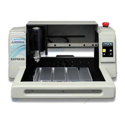
Vision Express S5 User manual

© 2018 Vision Engraving & Routing Systems
Vision Express S5 User Manual
Revised: 12/7/2018

All rights reserved. No parts of this work maybe reproduced in anyform or byanymeans - graphic, electronic, or
mechanical, including photocopying, recording, taping, or information storage and retrieval systems - without the
written permission of the publisher.
Products that are referred to in this document maybe either trademarks and/or registered trademarks of the
respective owners. The publisher and the author make no claim to these trademarks.
While everyprecaution has been taken in the preparation of this document,the publisher and the author assume no
responsibilityfor errors or omissions, or for damages resulting from the use of information contained in this
document or from the use of programs and source code that mayaccompanyit.In no event shall the publisher and
the author be liable for anyloss of profit or anyother commercial damage caused or alleged to have been caused
directlyor indirectlybythis document.
Revised: 12/7/2018
Vision Express S5 User Manual
© 2018 Vision Engraving & Routing Systems

3Contents
3
© 2018 Vision Engraving & Routing Systems
Table of Contents
Part I Introduction 5
................................................................................................................................... 61 Disclaimer and Warranty Information
................................................................................................................................... 82 Safety Precautions
Part II General Information 11
................................................................................................................................... 111 Unpacking & Inventory
................................................................................................................................... 122 Machine Description & Terminology
Part III Installation 15
................................................................................................................................... 151 Computer Requirements
................................................................................................................................... 162 Vision Software
................................................................................................................................... 273 Machine Connections
.......................................................................................................................................................... 29Direct Connection to Computer
.......................................................................................................................................................... 35Network Connection
Part IV The Front Panel 42
Part V Step by Step Operation 49
................................................................................................................................... 491 Holding Down Material
................................................................................................................................... 512 Zeroing the Cutter
................................................................................................................................... 513 Proximity Sensor
................................................................................................................................... 534 Step by Step Operation
.......................................................................................................................................................... 53Diamond Drag Engraving
......................................................................................................................................................... 54Example Job 1 - Diamond Drag
.......................................................................................................................................................... 66Rotary Engraving
......................................................................................................................................................... 67Example Job 2 - Rotary Engraving
.......................................................................................................................................................... 71Burnishing ......................................................................................................................................................... 74Example Job 3 - Burnishing
.......................................................................................................................................................... 84Profile Cutting
......................................................................................................................................................... 85Example Job 4 - Profile Cutting
.......................................................................................................................................................... 90Vectorizing Bitmaps and Creating Vector Fills
......................................................................................................................................................... 90Vectorizing a Bitmap in Vision Express 9 Software
......................................................................................................................................................... 93Vector Hatch Fills
................................................................................................................................... 1005 Advanced Operation
.......................................................................................................................................................... 100Setting and Using Custom Home Positions
.......................................................................................................................................................... 102Using the Measure Feature
.......................................................................................................................................................... 105Using the Red Dot Laser Pointer for Positioning
.......................................................................................................................................................... 108Creating a Center Driver
.......................................................................................................................................................... 116Adjusting Spindle Pressure
.......................................................................................................................................................... 119Installing Additional Drivers
Part VI Maintenance 122
................................................................................................................................... 1221 Multi Mat Information

Vision Express S5 User Manual4
© 2018 Vision Engraving & Routing Systems
................................................................................................................................... 1222 Cleaning
................................................................................................................................... 1243 Motion System Cleaning & Lubrication
................................................................................................................................... 1334 Changing the Motor Belt
................................................................................................................................... 1375 Changing the Motor Brushes
................................................................................................................................... 1386 Cleaning the Fan Filter
Part VII Troubleshooting 139
................................................................................................................................... 1391 Engraving Problems
................................................................................................................................... 1422 Mechanical Problems
Part VIII Optional Accessories 144
................................................................................................................................... 1441 Vacuum Chip Removal System
................................................................................................................................... 1452 Quick Lock Vise
................................................................................................................................... 1463 Hold Down Clamps
................................................................................................................................... 1484 Fixtures
................................................................................................................................... 1515 Clamping Vises

Introduction 5
© 2018 Vision Engraving & Routing Systems
1 Introduction
About This Manual
This manual provides you with information about the Vision Engraving or Routing system. Beginning with
unpacking the machine and continuing through installation, operation and lifetime machine maintenance.
This manual does not teach the user how to become an expert in engraving, computer usage, or
engraving software. Some previous knowledge of engraving terms and the engraving process is beneficial.
For information on the Vision Engraving Software, see the Vision Engraving Software manual.
For more information on your individual computer system, see your computer's user manual or contact
your computer distributor.
To begin, locate the White/Blue Dongle or Silver Dongle or
Blue/Silver USB Stick included with your machine in the
Accessories Box
Important Note:
The Vision software is available in two versions; one with a dongle, and one
that is "dongle-less" and is loaded on to a USB Memory stick.
If your machine was delivered with, or you currently have the white/blue or
orange software dongle, DO NOT LOSE IT!
The Vision software will NOT run without the dongle plugged into the computer.

Vision Express S5 User Manual6
© 2018 Vision Engraving & Routing Systems
1.1 Disclaimer and Warranty Information
Limits of Liability / Disclaimer of Warranty
The information contained within this manual has been carefully checked and is believed to be accurate,
however, Vision makes no representations or warranties for this manual, and assumes no responsibility
for inaccuracies, errors, or omissions that may be contained within this manual. In no event shall Vision
be liable for any loss of profit including (but not limited to) direct, indirect, special, incidental,
consequential, or other damages resulting from any defect or omission in this manual, even if previously
advised of the possibility of such damages.
In the interest of continued product development, Vision reserves the right to make improvements to this
manual and the products it describes at any time, without notice or obligation.
Limited Warranty:
Vision Computerized Engraving and Routing Systems (and Retrofit Tables)
Vision Computerized Engraving and Routing Systems (Vision) warrants that for a period of one (1) year
from the date of shipment to the original purchaser of an Express, VE810,or VR48 or a period of two (2)
years from the date of shipment to the original purchaser for a Phoenix1212, 1612Pro, 1624Pro, 2424,
2448, 2525Router, 2550Router, MaxPro, The MAX, or Table Retrofit (the System), that the System will
be free from defects in material and workmanship under normal use and service. Upon written
notification, we will transfer the remaining warranty to a new customer. This warranty shall cover all
elements except for items covered by separate manufacturer’s warranties and consumable items.
“Consumable” items include, but shall not be limited to, belts, brushes, lubricants, and cutters furnished
with the System, for which no warranty is provided.
In the event a defect is discovered during the warranty period, within thirty days of discovery, but no later
than the last day of the warranty period as described above, the user shall contact Vision for instructions
regarding disposition of the problem. Vision shall, at its option, either (1) repair the affected product with
new or refurbished parts, or (2) provide a replacement. Any incidental costs, including the cost of
shipment from the user’s location to the point of repair and return, and any installation performed by the
user, shall be at the expense of the user.
This warranty covers normal use only and shall be void in the event that the System is altered or modified
without authorization by Vision, or is subject to abuse, neglect, or other misuse by the user.
The warranties for Third-Party Hardware and Third-Party Software shall run directly from the
manufacturers of such hardware and software to the user. Vision makes no warranties, expressed or
implied, with regard to Third-Party Hardware or Third-Party Software.
Vision does not warrant any product, component, or part not manufactured by Vision that was not
supplied by Vision. (Third-party items, including but not limited to software, are subject to their own
manufacturer’s warranties.) Vision does not warrant defects caused by a failure to provide a suitable
environment for the system, by unauthorized attachments, by modifications or repairs other than by
Vision, by use of the System for other than its original intention, or by other misuse or abuse of the
System.
Extended Warranty
An Extended Warranty may be purchased which extends the terms of the original equipment Warranty in
1 year increments for a period of up to 30 days after the original equipment Warranty expires. An
Extended Warranty may also be purchased for a period of up to 30 days after an existing Extended
Warranty expires. Extended Warranties cannot be purchased on any equipment that is 7 or more years
old, or if there is a Lapse of Warranty. Age of equipment is determined from the date of shipment to the
original buyer.
Introduction 7
© 2018 Vision Engraving & Routing Systems
Lapse of Warranty
If an Extended Warranty is not purchased within 30 days of the expiration of the original equipment
Warranty, or within 30 days of the expiration of an existing Extended Warranty, the equipment will be in
Lapse of Warranty. An Extended Warranty can never again be purchased for any equipment that is in
Lapse of Warranty. It is the responsibility of the purchaser of the equipment to maintain accurate records
and to know the expiration date of any Warranty.
The above and foregoing is the only warranty of any kind, either expressed or implied, by statute or
otherwise, regarding the System, its fitness, quality, merchantability, or otherwise. Any warranties
implied by law are hereby expressly disclaimed. No oral or written information or advice given by Vision,
its Dealers, Distributors, Agents, or Employees shall create a warranty or in any way increase the scope
of this warranty. Neither Vision, nor anyone else who has been involved in the creation, production, or
delivery of the System shall be liable for any direct, indirect, consequential, or incidental damages
(including damages for loss of business profits, business interruption, loss of business information, and
the like) arising out of the use of, or inability to use, the product.
Any software supplied by Vision in conjunction with the purchase of the System for use therewith shall
be governed by its own separate software license and warranty agreement.
Terms and Conditions are subject to change
For Warranty Service Call: (602) 439-0600
Please have your machine serial number ready before calling.
Vision Engraving & Routing Systems is owned and operated by Western Engraver's Supply, Inc.
Phoenix, Arizona, USA

Vision Express S5 User Manual8
© 2018 Vision Engraving & Routing Systems
1.2 Safety Precautions
Ø WARNING: Do not attempt to operate this equipment until you have read and understood the
instructions in this User's Manual! Failure to comply may result in damage to the equipment
and/or inflict serious personal injury!
Ø Only trained personnel should operate the Vision Engraver or Router. All individuals operating
this equipment must read and understand the User's Manual and have been trained by a
competent authorized user.
ØUse of this equipment by unauthorized and/or untrained personnel may result in damage to
the equipment and/or inflict serious personal injury.
ØNever use this equipment in a hazardous environment. Do not store or use this machine
outdoors. Do not run this machine in an extremely hot environment.
ØPlace the equipment in a location with low humidity and a minimum of dust. Avoid placing in
direct sunlight or in locations with excessive heat.
ØDo not expose the equipment to rain or use near water. You can clean the equipment with a
damp cloth, but be sure to unplug it first.
ØFollow the maintenance instructions for proper cleaning of the air filter if equipped.
ØThere are no serviceable parts inside the controller. Please contact qualified service
personnel for any service issues.
ØOpenings and/or fans are provided on machines and controllers. Do not cover them or place
in an environment where they may become blocked. Never insert anything into the openings
or fans as doing so may create danger of electric shock.
ØAlways stop the machine before making any adjustments.

Introduction 9
© 2018 Vision Engraving & Routing Systems
ØKeep hands clear of the bottom of the spindle during operation.
Ø Do not operate the machine with the covers removed.
ØUse extreme caution when inserting or removing cutters
Ø Before servicing, disconnect the power cord.
ØTo avoid electric shock or equipment damage, connect power to this machine according to
this guide and in compliance with all applicable laws and regulations.
ØNever operate the equipment with damaged or frayed power cords, loose connections, or
exposed extension cords where the cord could create a tripping hazard.
Ø Be sure to hold the plug, not the cord, when disconnecting the machine from a power source.
Ø Keep work area clean. Remove adjustment tools from the machine prior to start-up. Cluttered
work areas increase the potential for accidents.
Ø Safety glasses should be worn at all times as chips and other debris may become airborne.
Ø Avoid loose clothing, neckties, gloves, rings, bracelets, jewelry and other items that may get
caught in moving parts.
Ø If your machine does not operate properly; in particular, if there are any unusual sounds or
smells coming from it, immediately unplug it and contact Vision's service department or your
local distributor.
Ø Unplug the machine when it is going to be left unused for an extended period of time.
ØOperators should inspect the machine daily for damage or modifications. Under no
circumstances should the machine be operated if there is any doubt about the machine
condition. If there are any questions call the Vision technical support team at 602-439-0600.
ØKeep a safe distance away from the machine while running.
ØKeep children away from work area at all times. Visitors should be a at least 3 feet from
working area.
ØDo not operate this or any machine while under the influence of drugs or alcohol.
Ø Keep hands away from the spindle at all times when spindle is rotating and/or machine is
moving. Always wait for spindle to stop rotating before attempting to insert or change a tool.

Vision Express S5 User Manual10
© 2018 Vision Engraving & Routing Systems
Do not try to stop the spindle manually with your hands or other devices. Failure to comply
with these instructions may result in serious personal injury!
Ø Never leave the machine unattended.
Ø Press any Emergency switch to stop the machine immediately. Be familiar with the location
of all emergency stop switches.
Ø Make sure workpiece is properly fastened to table before starting the job.
Ø Turn on the vacuum table (if equipped) or make sure clamps and other fixtures are fastened.
If workpiece moves during operation you can damage the machine, the workpiece, and
serious personal injury may occur to the operator.
Ø Only use the machine and its attachments for the applications they were designed for.
Forcing the machine or its attachments to do work it was not intended to do may cause
permanent damage to the machine and serious injury may occur to the operator. If there are
any questions about the abilities of your machine, please call the Vision technical support
team at 602-439-0600.
Ø Do not force the machine to work at excessive speeds. The machine will work safely under
normal speeds which are material and application dependent. Using excessive speeds may
damage tooling, material, the machine, and may cause serious injury.
Ø Do not power on the machine when servicing.
Ø Do not power on the machine when installing or replacing parts and/or accessories.
Ø Turn power to the machine OFF when not in use.
Ø Perform the required maintenance at the recommended intervals.
Ø Use the general maintenance guidlines to properly maintain your machine.
Ø A disciplined approach to preventative maintenance can extend the useful life of any machine,
improve cut quality, and reduce repair costs. Keep records of what and when you perform
maintenance duties.

Introduction 11
© 2018 Vision Engraving & Routing Systems
2 General Information
2.1 Unpacking & Inventory
The Express engraving system has been shipped in one carton, unless other accessories have been
ordered with the machine that will not fit in the box. Examine the condition of the box for external
damage. In the event of apparent external damage, notify your shipping carrier upon receipt, and call your
sales representative or Vision immediately.
Note: The shipping container is considered reusable and should be stored for use in the event of service
need or upgrade.
Step1:
Open the foam packed shipping carton. In the top of the carton will be a cardboard box with all of the
machine accessories. The following items should be included:
ü
1 Express Machine
ü
1 Express Warranty Card
ü
1 Express Installation Guide
ü
1 White/Blue or Orange USB security dongle - Contains User Manual and Vision Software
ü
1 Ethernet Network Cable (P/N 20-1074-00)
ü
1 Power Cord
ü
1 External Power Supply (P/N 27-0050-00)
ü
1 0.015 FLXPlastic Cutter (P/N AC-175.015-FLX)
ü
1 Non-Rotating Diamond 120 Degree (P/N NRD-171-120)
ü
1 6 x 8 inch Multi Mat Material (P/N 15-1109-00)
ü
1 Spare Motor Belt (P/N 200507-14.75)
ü
1 Allen Wrench Set
ü
1 Cutter Wrench (P/N 200538-00)
ü
1 Technical Support Label
ü
1 Accessory Sheet
Check to see that all of the items are included. Should any of the contents be missing, damaged, or of
the incorrect type, please call your sales representative or Vision immediately.
Step 2:
Prepare a clean, level surface to put the engraving machine on. Carefully lift the machine out of the
carton and place it on the table.
Step 3:
After unpacking the machine, make sure that you SAVE THE CARTON, FOAM PACK and ANY OTHER
BOXES. They can be reused in the event the system must be transported to another location or returned
for service. Improper packaging for shipment can damage the machine and may void the warranty.

Vision Express S5 User Manual12
© 2018 Vision Engraving & Routing Systems
2.2 Machine Description & Terminology
This chapter briefly describes the major components of the Express engraver and will help you identify
the parts of your engraver which are discussed elsewhere in this manual.
SPECIFICATIONS:
Z-Axis Clearance: 1.25 inch (31.75 mm)
(Definition: the distance between the bottom of the spindle and the work surface)
Z-Axis Stroke: 1.25 inch (31.75 mm)
(Definition: the travel distance of the Z-axis mechanism or spindle)
Table Resolution: .0002 inch
(Definition: the smallest controlled motion the table is capable of)
Maximum Speed: 2 inches per second (50.8 mm/s)
Spindle Type: 11/64 inch (4.366 mm) top load
Maximum Work Area: 6 inch x 8 inch (152.4 mm x 203.2 mm)
Maximum Work Piece Size 8 inch (203.2 mm) x Unlimited
Overall Dimensions H x W x D: 9.5 inch x 17.5 inch x 17.5 inch
(241.3 mm x 444.5 mm x 444.5 mm)
Table Top: T-Slot
Interface: Ethernet
Controller: Embedded
Power Requirements: 100 - 240 VAC
Shipping Weight: 52 lbs. Ground, 61 lbs. Air
Actual Weight: 24 lbs.
Shipping Dimensions: 23" x 23" x 19"
DEFINITION OF TERMS (see Figures below)
1. Front Panel - Allows the user to start, pause, and resume operation. The user can also jog, set
home, load and save jobs, configure settings and many other actions. For complete details see the Front
Panel section of this manual.
2. Emergency Stop - A push button emergency shut down of the motion system (does not turn
machine completely off, stops motion by cutting power to the spindle motor and stepper motors).
Figure 1.1 Figure 1.2

General Information 13
© 2018 Vision Engraving & Routing Systems
3. X-Axis Leadscrew - The screw that drives the left to right motion of the machine.
4. X-Axis Linear Rail - The square rail that the carriage assembly rides on.
5. Y-Axis Linear Rail - The square rail that the t-slot table rides on.
6. Y-Axis Leadscrew - The screw that drives the front to back motion of the machine.
7. T-Slot Table (work surface) - Allows the user to position the engraving material or special clamps
and fixtures. The slots in the table are shaped with an upside-down T. The slots are used to hold various
accessory holders, clamps, and jigs.
8. Table Home Position - The upper-left corner of the T-Slot table. All work is referenced from this
position.
9. Spindle Cover - Protects user from rotating spindle during operation.

Vision Express S5 User Manual14
© 2018 Vision Engraving & Routing Systems
Figure 1.3
10. Spindle - Holds various cutters and allows for cut depth adjustments.
11. Motor Belt - Supplies rotary motion to the spindle.
12. Spindle Motor Pulley (not shown) - Behind the spindle, and attached via the motor belt, the motor
pulley drives the spindle rotation when rotary engraving or cutting. (The spindle motor pulley is hidden by
two covers).
13. Spindle Pulley - The top part of the spindle where the motor belt rides.
14. Spindle Micrometer - The part of the spindle that the user adjusts to set engraving depth.
15. Spindle Nose Cone - The part of the spindle that rides on top of the material while engraving.
Cutting depth is determined by the distance the cutting tool extends below the bottom of the nose cone.
Figure 1.4

General Information 15
© 2018 Vision Engraving & Routing Systems
3 Installation
NOTE: ITIS HIGHLY RECOMMENDED THAT THE COMPUTER USED TO OPERATE THE VISION
ENGRAVER OR ROUTER BE CONNECTED TO THE INTERNET. THIS ALLOWS THE USER TO
ALLOW VISION'S TECHNICAL SUPPORT TO ACCESS THE MACHINE AND TROUBLESHOOT IF
NECESSARY.
3.1 Computer Requirements
Minimum System
Requirements:
CPU:
Dual Core (2.0GHz or higher)
Hard Drive:
750 GB free space
RAM:
1GB + OS Requirements
Operating System:
Windows 10 (32/64 bit)
Windows 8 (32/64 bit)
Windows 7 SP.1 (32/64 bit) ***Requires Service Pack 1
Ports:
USB port for security dongle
Local or network Ethernet port to connect machine
Suggested System
Requirements
CPU:
Core i3 (or faster)
Hard Drive:
1 TB (or more)
RAM::
4GB + OS Requirements
Operating System:
Windows 10 (32/64 bit)
Windows 8 (32/64 bit)
Windows 7 SP.1 (32/64 bit) ***Requires Service Pack 1
Ports
USB port for security dongle
Local or network Ethernet port to connect machine

Vision Express S5 User Manual16
© 2018 Vision Engraving & Routing Systems
3.2 Vision Software
Insert the Vision USB dongle into the USB port on the computer. Navigate to the Devices and Drives
area on your PC. Double click on the Vision icon to open the files on the USB dongle.
Select the Start or Start.exe file to begin.
Click on the Install Vision Software button.

Installation 17
© 2018 Vision Engraving & Routing Systems
The Vision S5 Software Wizard will guide you through the process of installing the software. Press Next
to continue.
Press Install to continue

Vision Express S5 User Manual18
© 2018 Vision Engraving & Routing Systems
Setup wizard will install the program.
Select Finish to continue the software installation.
Choose your preferred language and click ok.

Installation 19
© 2018 Vision Engraving & Routing Systems
The Vision 10 Setup Screen will appear. Press Next.
After accepting the license agreement, click on the Next button.

Vision Express S5 User Manual20
© 2018 Vision Engraving & Routing Systems
Select Next (or change the destination folder - not recommended).
Select Next to create the folder.
Other manuals for Express S5
1
Table of contents
Other Vision Engraver manuals

Vision
Vision Express S5 User manual

Vision
Vision Phoenix 1212 S5 User manual

Vision
Vision Phoenix 1212 User manual

Vision
Vision Cylindrical User manual

Vision
Vision VE810 S5 User manual

Vision
Vision PHOENIX TABLE User manual

Vision
Vision SP Series User manual

Vision
Vision MAX Pro User manual

Vision
Vision MAX Pro User manual

Vision
Vision VE810 4 Series User manual