GE BAKER HUGHES DPS 5000 Series User manual

GE
Measurement & Control
DPS 5000 Series Sensors
I2C-bus Pressure Transducer
User Manual – K0582
English

Druck Ltd., Fir Tree Lane, Groby. Leicester, LE6 0FH, UK.
Tel: +44 (0)116 231 7100; Fax +44 (0)116 231 7103
© 2015 General Electric Company. All rights reserved

K0582 Revision B May 2015 i
Safety
The manufacturer has designed this sensor to be safe when operated using the procedures
detailed in this manual. Do not use this sensor for any other purpose than that stated.
This manual contains operating and safety instructions that must be followed for safe
operation and to maintain the sensor in a safe condition. The safety instructions are either
warnings or cautions issued to protect the user and the equipment from injury or damage.
Use qualified personnel and good engineering practice for all procedures in this manual.
Qualified personnel must have the necessary technical knowledge, documentation, special
test equipment and tools to carry out required work on this sensor.
Pressure Do not apply pressure greater than the maximum safe working pressure
to the sensor.
Toxic materials There are no known toxic materials used in the sensor.
Maintenance The sensor must be maintained using the manufacturer’s procedures
and these should be carried out by authorised service agents or the
manufacturer’s service departments.
Technical advice For technical advice contact the manufacturer.
EC Directives This sensor complies with the requirements of the Pressure Equipment
Directive 97/23/EEC and the EMC directive 2004/108/EC1.
For further details refer to the Sales Data Sheet or the customer
specification drawing.
A full conformity certificate is available from the manufacturer.
Contact GE Measurement & Control www.gemeasurement.com
1The EMC directive is only applicable to the external variant (model E503D)

ii May 2015 K0582 Revision B
Abbreviations
The following abbreviations are used in this manual.
Note: Abbreviations are the same in the singular and plural
ADC Analogue to digital converter
Addr Address
ASCII American standard code for information interchange
atm atmosphere
ESD Electro-static discharge
ftH2O Feet of water
hPa HectoPascal
Hz Hertz
I2C Inter-integrated circuit
IEEE Institute of Electrical and Electronic Engineers
inHg Inch of Mercury
inH2O Inch of water
kbit/s Kilobits per second
kbyte Kilobytes (1024 bytes)
kgf/cm2Kilogram-force per square centimetre
kPa KiloPascal
LSB Least significant bit/byte
mbar Millibar
mH2O Metre of water
mmHg Millimetre of Mercury
mmH2O Millimetre of water
MPa MegaPascal
ms Millisecond
MSB Most significant bit/byte
PCB Printed circuit board
psi Pound per square inch
s Second
SNR Signal to noise ratio
°C Degrees Celsius
Nomenclature
The following number notations are used in this document.
0bn..n Binary number notation, e.g. 0b10
0xn..n Hexadecimal number notation, e.g. 0x3BF0
The following data types are used in this document.
Type
Bits
Range
Unsigned byte
8
0x00 (0) to 0xFF (255)
Unsigned integer
16
0x0000 (0) to 0xFFFF (65535)
Unsigned word
32
0x00000000 (0) to 0xFFFFFFFF (4294967295)
Float
32
0xFF7FFFFF (-3.4028E-38) to 0x7F7FFFFF (+3.4028E+38) NOTE 1
Extended ASCII
8
0x00 (NULL) to 0xFF (ÿ) NOTE 2
NOTE 1: Data type float to IEEE 754. NOTE 2: Data type Extended ASCII to ISO 8859-1

K0582 Revision B May 2015 iii
References
Reference 1 I2C-bus specification and user manual, NPX Semiconductor UM10204 Rev. 6
available from www.nxp.com

iv May 2015 K0582 Revision B
Contents
1Introduction 1
General 11.1
Configuration 11.2
2Installation 2
General 22.1
Mounting and orientation 22.2
Connecting to the pressure source 22.3
Electrical connections 32.4
3Functional description 4
Sensor communication 43.1
Memory map 5
3.2
Register descriptions 53.3
Register bit table legend 53.3.1
Address 0 - STATUS 63.3.2
Address 1 – COMP_PRES 73.3.3
Address 2 – COMP_TEMP 83.3.4
Address 3 – ADC_PRES 83.3.5
Address 4 – ADC_TEMP 93.3.6
Address 5 – ACCESS 93.3.7
Address 6 – MVOLT_PRES 93.3.8
Address 7 – MVOLT_TEMP 103.3.9
Address 66 – I2C_ADDR 103.3.10
Address 67 – COEF_FIT 11
3.3.11
Address 68 – GAIN_ADJ 113.3.12
Address 69 – OFFSET_ADJ 123.3.13
Address 70 – MAX_RANGE 123.3.14
Address 71 – MIN_RANGE 123.3.15
Address 72 – CAL_DATE 133.3.16
Address 73 – MAX_ADC_PRES 133.3.17
Address 74 – MIN_ADC_PRES 143.3.18
Address 75 – MAX_ADC_TEMP 143.3.19
Address 76 – MIN_ADC_TEMP 143.3.20
Address 77 – SERIAL 153.3.21
Address 78 – CONFIG 153.3.22
Address 79 – VERSION 16
3.3.23
Address 82 – AVERAGE 163.3.24
Address 83 – PRES_CONV 173.3.25
Address 84 – PRES_UNIT 173.3.26
Address 85 – DELAY 183.3.27
Address 86 - SPEC_DWG 193.3.28
Address 87 – TARE_VALUE 193.3.29
Addresses 128-157 - Pressure coefficients 193.3.30
Addresses 158-187 - Temperature coefficients 203.3.31

K0582 Revision B May 2015 v
4Operational description 20
Operational states 20
4.1
Reading the pressure and temperature 214.2
Updating the pressure and temperature 214.3
Manual update 214.3.1
Automatic update 224.3.2
Updating the sensor configuration data registers 224.4
User modifiable registers 224.4.1
Modifying the I2C-bus address 234.4.2
Changing the auto-update period 234.4.3
Changing the unit of pressure 244.4.4
Reading relative pressure 244.4.5
Pressure and temperature SNR 254.4.6
Maximising the update rate 26
4.4.7
Pressure re-calibration 264.4.8
5Maintenance 27
Cleaning 275.1
Adjustment 285.2
Repair 285.3
Disposal 285.4
Annex A Unit of pressure conversion factors 29
List of figures
Figure 1 External and internal DPS 5000 sensors – General view 1
Figure 2 Pressure connection 3
Figure 3 Typical I2C-bus network 3
Figure 4 Typical I2C-bus data transfers 4
Figure 5 Bit table legend 6
Figure 6 Operational states 20
Figure 7 Interaction legend 21
Figure 8 Noise level correction factors 25
List of tables
Table 1 Electrical connections 4
Table 2 I2C-bus feature support 4
Table 3 Memory map 5
Table 4 User modifiable registers 22

vi May 2015 K0582 Revision B
Page left intentionally blank

K0582 Revision B May 2015 1
1Introduction
General1.1
The DPS 5000 series sensor is a microcontroller based smart pressure transducer
that provides a digital output through an I2C-bus interface. The sensor is available
as either an external or internal variant. The external variant is a sealed device with
the electrical connections made via an integral cable. The internal variant is an
open frame device with electrical connections made via an integral plug.
Figure 1 External and internal DPS 5000 sensors – General view
The DPS 5000 series sensors are low powered devices offering a high level of
accuracy over a wide temperature range. The I2C-bus interface provides
compensated pressure and temperature readings and allows the sensor operation
to be software controlled.
Configuration1.2
The following options are available at the time of ordering:
a) External or internal sensor variant
b) Pressure range
c) Pressure connector
Each sensor is supplied with the following documentation:
d) Hazardous area installation instructions2:
Document K0546 for the external sensor variant
Document K0547 for the internal sensor variant
e) Calibration certificate
2Only supplied with hazardous area certified sensors

2 May 2015 K0582 Revision B
2Installation
General2.1
Before installing the DPS 5000 series sensor:
xEnsure that the sensor is the correct type for the application and will not be
subject to pressures or media outside those specified on the applicable
datasheet or specification drawing.
xIf the sensor is being installed in a hazardous area observe the installation
instructions given in the supplied document K0546 or K0547.
xRead all relevant instructions and procedures in the applicable system
installation manual.
To prevent contamination prior to installation, keep the sensor in the original
packaging with all the supplied covers fitted.
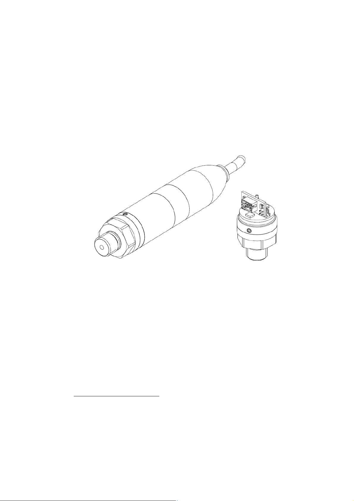
When installing the internal variant, to prevent possible damage, avoid touching or
applying excessive force to the exposed PCB assemblies.
WARNING
Do not interchange sensors between an oil system and a system that uses fuel or
gas. This can cause an explosion resulting in death or injury and/or damage to
equipment.
High pressures and extremes of temperature are dangerous. De-pressurize and
allow components to attain an acceptable temperature in systems where high
pressures and high or low temperatures are present.
CAUTION
The sensor contains ESD sensitive devices. Whilst the sensor incorporates
protection against ESD, caution should be taken to observe proper ESD handling
procedures when installing the internal variant.
Mounting and orientation2.2
The DPS 5000 series sensors are designed to be mounted in any orientation.
However, the sensor is a harsh media isolated product and the isolation is achieved
by hermetically sealing the sensor chip within an oil filled chamber. The weight of
the oil gives a g-sensitivity as a pressure offset error that may be noticeable at the
lowest pressure ranges.
Ensure the sensor is mounted in a manner that avoids unwanted mechanical or
thermal stress such as vibration, shock or excessive or rapid temperatures
excursions.
Connecting to the pressure source2.3
When connecting the pressure source to the sensor, ensure the mating surfaces are
correctly sealed. Failure to properly seal may affect the sensor performance or
calibration accuracy.
Male parallel threaded pressure connectors must not be sealed or constrained
against the face at the base of the thread. The forward flat face should be used as
shown in Figure 2.

K0582 Revision B May 2015 3
Figure 2 Pressure connection
Torque tighten the sensor in accordance with the system installation manual.
Electrical connections2.4
The DPS 5000 series sensors employ a 4 wire I2C-bus user electrical interface:
Supply +
Serial data (SDA)
Serial clock (SCL)
Supply –
The sensor may be used standalone or as part of a network of compatible I2C-bus
devices.
CAUTION
The DPS 5000 is intended for use within networks operated from a single supply
at a voltage within the range 2.7 V to 3.6 V. Operation outside these limits is not
guaranteed and may damage the sensor.
The sensor interface includes 2 reserved signals. These should be left open circuit
as connecting to these signals may result in incorrect sensor operation.
Figure 3 Typical I2C-bus network
The electrical connections to the sensors are colour coded as shown in Table 1.

4 May 2015 K0582 Revision B
Signal
External variant
Internal variant
Plug pin NOTE 1
Supply +
Red
Red
1
Serial data
Orange
Yellow
2
Serial clock
Black
Green
3
Supply -
White
Blue
4
Reserved
Yellow & Blue
Orange & Black
5 & 6
Case
Screen
-
-
NOTE 1: The mating connector for the internal variant plug is a Molex Milli-GridTM connector system
6 pin crimp housing part number 0511100660 with crimp terminals part number 0503948051
or 0503948100.
Table 1 Electrical connections
3Functional description
Sensor communication3.1
The DPS 5000 series sensors appear on the I2C-bus as a slave device containing a
number of memory mapped registers that are used to control the operation of the
sensor and to provide information about the sensor and its environment. Table 2
summarizes the features of the I2C-bus specification, Reference 1, that are
supported by the DPS 5000 series sensors.
Feature
Applicability
Feature
Applicability
Standard mode
Supported
10 bit addressing
Not supported
Fast mode
Not supported
General call address
Not supported
Fast mode plus
Not supported
Clock stretching
Supported
High speed mode
Not supported
Software reset
Not supported
7 bit address
Supported
Device ID
Not supported
Table 2 I2C-bus feature support
Each slave device on an I2C-bus network must have a unique address. The default
address for the DPS 5000 series sensors is 2, but may be changed over the bus as
required to any value within the range 1 to 127.
The DPS 5000 series sensors support the I2C-bus standard mode to permit data
transfers to or from the sensor up to 100 kbit/s under the control of the network I2C-
bus master. Data transfers may use any of the 3 I2C-bus data transfer formats to
achieve the sensor register read and write protocols shown in Figure 4.
Figure 4 Typical I2C-bus data transfers
When reading from or writing to the sensor, the master first performs a 1 byte data
write to send the required register address to the sensor. The master then performs
either an nbyte data read or write to transfer the data, LSB first, from or to the

K0582 Revision B May 2015 5
addressed register. As the sensor registers are 32 bits wide, the read and write
transfers are generally 4 bytes long. However, 1, 2 or 3 byte transfers are allowed.
Memory map3.2
The DPS 5000 sensor registers are mapped within a 1 kbyte memory space. As each
register is 4 bytes wide, the register addresses range from 0 to 255. Not all the
address space is available to the user, some addresses are reserved whilst others
are unused. The reserved addresses cannot be written to and read as 0x00000000.
Unused addresses cannot be written to and read as 0xFFFFFFFF.
The registers are grouped into 3 blocks: volatile data, configuration data and
coefficient data as shown in Table 3.
Volatile data
Configuration data
Coefficient data
Addr
Register
Addr
Register
Addr
Register
0
STATUS
64
Reserved
128
Up to 30
pressure
coefficient
registers
1
COMP_PRES
65
Reserved
.
2
COMP_TEMP
66
I2C_ADDR
.
3
ADC_PRES
67
COEF_FIT
.
4
ADC_TEMP
68
GAIN_ADJ
.
5
ACCESS
69
OFFSET_ADJ
.
6
MVOLT_PRES
70
MAX_RANGE
.
7
MVOLT_TEMP
71
MIN_RANGE
.
8
Reserved
72
CAL_DATE
157
.
.
73
MAX_ADC_PRES
158
Up to 30
temperature
coefficient
registers
.
.
74
MIN_ADC_PRES
.
.
.
75
MAX_ADC_TEMP
.
.
.
76
MIN_ADC_TEMP
.
.
.
77
SERIAL
.
.
.
78
CONFIG
.
.
.
79
VERSION
.
.
.
80
Reserved
.
.
.
81
Reserved
.
.
.
82
AVERAGE
187
.
.
83
PRES_CONV
188
Unused
.
.
84
PRES_UNIT
.
.
.
.
85
DELAY
.
.
.
.
86
SPEC_DWG
.
.
.
.
87
TARE_VALUE
.
.
.
.
88
Reserved
.
.
.
.
.
.
.
.
.
.
.
.
.
.
.
.
.
.
.
.
63
Reserved
127
Reserved
255
Unused
Table 3 Memory map
Register descriptions3.3
Register bit table legend3.3.1
The legend used for the bit tables within this section is shown in Figure 5.

6 May 2015 K0582 Revision B
Figure 5 Bit table legend
Not all bits within a register are available to the user. Reserved bits always read as
0b0 and writes have no effect. Unused bits are readable and writable but have no
effect on the sensor operation.
Address 0 - STATUS3.3.2
Bit 31
Bit 30
Bit 29
Bit 28
Bit 27
Bit 26
Bit 25
Bit 24
Reserved
Reserved
Reserved
Reserved
Reserved
Reserved
Reserved
Reserved
R-0
R-0
R-0
R-0
R-0
R-0
R-0
R-0
Bit 23
Bit 22
Bit 21
Bit 20
Bit 19
Bit 18
Bit 17
Bit 16
Reserved
Reserved
Reserved
Reserved
Reserved
Reserved
Reserved
Reserved
R-0
R-0
R-0
R-0
R-0
R-0
R-0
R-0
Bit 15
Bit 14
Bit 13
Bit 12
Bit 11
Bit 10
Bit 9
Bit 8
RESET [1..0]
CLRQERR
TARE
SET_TARE
QERR
INTRDG
AUTO
W-0
W-0
W-0
R/W-0
W-0
R-0
RW-0
R/W-0
Bit 7
Bit 6
Bit 5
Bit 4
Bit 3
Bit 2
Bit 1
Bit 0
Reserved
Reserved
WRITE
ADC_ON
WENB
VALID [1..0]
CONV
R-0
R-0
W-0
R-X
R-0
R-X
R-X
R/W-X
Bit 31–16 Reserved, read as 0
Bit 15–14 RESET [1..0]: Write only - performs a sensor reset equivalent to cycling the
sensor power.
0b00 No action
0b01 No action
0b10 Reset
0b11 No action
Bit 13 CLRQERR: Write only - used to clear the QERR (bit 10) and the CONV (bit 0) flags.
0b0 No action
0b1 Clear flags
Bit 12 TARE: Read/write – used to enable the sensor tare mode. When enabled, the
COMP_PRES register (address 1) is set to the actual compensated pressure
minus the current value of the TARE_VALUE register (address 87).
0b0 Disabled
0b1 Enabled
Bit 11 SET_TARE: Write only – used to copy the current value of the COMP_PRES
register (address 1) to the TARE_VALUE register (address 87).
0b0 No action
0b1 Copy data
Bit 10 QERR: Read only - set when an internal queue error is detected whilst AUTO
(bit 8) is set. Reset using CLRQERR (bit 13).

K0582 Revision B May 2015 7
0b0 No error
0b1 Error
Bit 9 INTRDG: Read/write – used to enable the sensor interleave mode. ADC_ON (bit
4) is always set when enabled, and alternate pressure and temperature ADC
values are used to generate the updated pressure and temperature readings.
0b0 Disabled
0b1 Enabled
Bit 8 AUTO: Read/write – used to enable the sensor auto-update mode. When
enabled pressure and temperature readings are updated automatically at a
rate determined by the value of the DELAY register (address 85).
0b0 Disabled
0b1 Enabled
Bit 7–6 Reserved, read as 0
Bit 5 WRITE: Write only – used to transfer the current values of the configuration
data registers to non-volatile memory when WENB (bit 3) is set.
0b0 No action
0b1 Transfer data
Bit 4 ADC_ON: Read only – indicates when the sensor ADC and bridge are active.
0b0 Inactive
0b1 Active
Bit 3 WENB: Read only – indicates the write status of the configuration data
resisters. It is set and cleared by writing to the ACCESS register (address 5).
0b0 Not writable
0b1 Writable
Bit 2–1 VALID[1..0]: Read only – used to indicate the status of the current values held
in the COMP_PRES and COMP_TEMP registers (addresses 1 and 2).
Automatically cleared by reading the COMP_PRES, COMP_TEMP, ADC_PRES,
ADC_TEMP, MVOLT_PRES or MVOLT_TEMP register (addresses 1, 2, 3, 4, 6 and 7
respectively) whilst the sensor is in the auto-update mode.
0b00 Error – invalid pressure and temperature ADC values detected
0b01 Error – invalid temperature ADC value detected
0b10 Error – invalid pressure ADC value detected
0b11 Data valid
Bit 0 CONV: Read/write – used to trigger an update of the COMP_PRES and
COMP_TEMP registers (addresses 1 and 2) and to indicate when the registers
have been updated. Cleared by writing 0b0, using CLRQERR (bit 13) or by
reading the COMP_PRES, COMP_TEMP, ADC_PRES, ADC_TEMP, MVOLT_PRES or
MVOLT_TEMP register (addresses 1, 2, 3, 4, 6 and 7 respectively) whilst the
sensor is in the auto-update mode.
0b0 Read = data not updated / Write = clear bit
0b1 Read = data updated / Write = request update
Address 1 – COMP_PRES3.3.3
Bit 31
Bit 30
Bit 29
Bit 28
Bit 27
Bit 26
Bit 25
Bit 24
COMP_PRES [31..24]
R-X
Bit 23
Bit 22
Bit 21
Bit 20
Bit 19
Bit 18
Bit 17
Bit 16
COMP_PRES [23..16]
R-X

8 May 2015 K0582 Revision B
Bit 15
Bit 14
Bit 13
Bit 12
Bit 11
Bit 10
Bit 9
Bit 8
COMP_PRES [15..8]
R-X
Bit 7
Bit 6
Bit 5
Bit 4
Bit 3
Bit 2
Bit 1
Bit 0
COMP_PRES [7..0]
R-X
Bit 31–0 COMP_PRES [31..0]: Read only – the most recently updated compensated
pressure value in the pressure units defined by the PRES_UNIT register
(address 84). Reading this register whilst the sensor is in the auto-update
mode will clear the CONV (bit 0) flag of the STATUS register (address 0).
0xn..n Number type float
Address 2 – COMP_TEMP3.3.4
Bit 31
Bit 30
Bit 29
Bit 28
Bit 27
Bit 26
Bit 25
Bit 24
COMP_TEMP [31..24]
R-X
Bit 23
Bit 22
Bit 21
Bit 20
Bit 19
Bit 18
Bit 17
Bit 16
COMP_TEMP [23..16]
R-X
Bit 15
Bit 14
Bit 13
Bit 12
Bit 11
Bit 10
Bit 9
Bit 8
COMP_TEMP [15..8]
R-X
Bit 7
Bit 6
Bit 5
Bit 4
Bit 3
Bit 2
Bit 1
Bit 0
COMP_TEMP [7..0]
R-X
Bit 31–0 COMP_TEMP [31..0]: Read only – the most recently updated compensated
temperature value in °C. Reading this register whilst the sensor is in the auto-
update mode will clear the CONV (bit 0) flag of the STATUS register (address 0).
0xn..n Number type float
Address 3 – ADC_PRES3.3.5
Bit 31
Bit 30
Bit 29
Bit 28
Bit 27
Bit 26
Bit 25
Bit 24
ADC_PRES [31..24]
R-X
Bit 23
Bit 22
Bit 21
Bit 20
Bit 19
Bit 18
Bit 17
Bit 16
ADC_PRES [23..16]
R-X
Bit 15
Bit 14
Bit 13
Bit 12
Bit 11
Bit 10
Bit 9
Bit 8
ADC_PRES [15..8]
R-X
Bit 7
Bit 6
Bit 5
Bit 4
Bit 3
Bit 2
Bit 1
Bit 0
ADC_PRES [7..0]
R-X
Bit 31–0 ADC_PRES [31..0]: Read only – the most recently updated pressure ADC value.
This value is used to calculate the value held in the MVOLT_PRES register
(address 6). Reading this register whilst the sensor is in the auto-update mode
will clear the CONV (bit 0) flag of the STATUS register (address 0).
0xn..n Number type unsigned word

K0582 Revision B May 2015 9
Address 4 – ADC_TEMP3.3.6
Bit 31
Bit 30
Bit 29
Bit 28
Bit 27
Bit 26
Bit 25
Bit 24
ADC_TEMP [31..24]
R-X
Bit 23
Bit 22
Bit 21
Bit 20
Bit 19
Bit 18
Bit 17
Bit 16
ADC_TEMP [23..16]
R-X
Bit 15
Bit 14
Bit 13
Bit 12
Bit 11
Bit 10
Bit 9
Bit 8
ADC_TEMP [15..8]
R-X
Bit 7
Bit 6
Bit 5
Bit 4
Bit 3
Bit 2
Bit 1
Bit 0
ADC_TEMP [7..0]
R-X
Bit 31–0 ADC_TEMP [31..0]: Read only – the most recently updated temperature ADC
value. This value is used to calculate the value held in the MVOLT_TEMP
register (address 7). Reading this register whilst the sensor is in the auto-
update mode will clear the CONV (bit 0) flag of the STATUS register (address 0).
0xn..n Number type unsigned word
Address 5 – ACCESS3.3.7
Bit 31
Bit 30
Bit 29
Bit 28
Bit 27
Bit 26
Bit 25
Bit 24
ACCESS [31..24]
W-0
Bit 23
Bit 22
Bit 21
Bit 20
Bit 19
Bit 18
Bit 17
Bit 16
ACCESS [23..16]
W-0
Bit 15
Bit 14
Bit 13
Bit 12
Bit 11
Bit 10
Bit 9
Bit 8
ACCESS [15..8]
W-0
Bit 7
Bit 6
Bit 5
Bit 4
Bit 3
Bit 2
Bit 1
Bit 0
ACCESS [7..0]
W-0
Bit 31–0 ACCESS [31..0]: Write only – used to clear or set WENB (bit 3) of the STATUS
register (address 0).
0xn..n Number type unsigned word
0 Clear WENB
4118 Set WENB
Address 6 – MVOLT_PRES
3.3.8
Bit 31
Bit 30
Bit 29
Bit 28
Bit 27
Bit 26
Bit 25
Bit 24
MVOLT _PRES [31..24]
R-X
Bit 23
Bit 22
Bit 21
Bit 20
Bit 19
Bit 18
Bit 17
Bit 16
MVOLT _PRES [23..16]
R-X
Bit 15
Bit 14
Bit 13
Bit 12
Bit 11
Bit 10
Bit 9
Bit 8
MVOLT _PRES [15..8]
R-X
Bit 7
Bit 6
Bit 5
Bit 4
Bit 3
Bit 2
Bit 1
Bit 0
MVOLT _PRES [7..0]
R-X

10 May 2015 K0582 Revision B
Bit 31–0 MVOLT _PRES [31..0]: Read only – the most recently updated pressure sensing
element output voltage. This value is used in conjunction with the pressure
and temperature coefficient registers to calculate the values held in the
COMP_PRES and COMP_TEMP registers (addresses 1 and 2). Reading this
register whilst the sensor is in the auto-update mode will clear the CONV (bit 0)
flag of the STATUS register (address 0).
0xn..n Number type float
Address 7 – MVOLT_TEMP3.3.9
Bit 31
Bit 30
Bit 29
Bit 28
Bit 27
Bit 26
Bit 25
Bit 24
MVOLT _TEMP [31..24]
R-X
Bit 23
Bit 22
Bit 21
Bit 20
Bit 19
Bit 18
Bit 17
Bit 16
MVOLT _TEMP [23..16]
R-X
Bit 15
Bit 14
Bit 13
Bit 12
Bit 11
Bit 10
Bit 9
Bit 8
MVOLT _TEMP [15..8]
R-X
Bit 7
Bit 6
Bit 5
Bit 4
Bit 3
Bit 2
Bit 1
Bit 0
MVOLT _TEMP [7..0]
R-X
Bit 31–0 MVOLT _TEMP [31..0]: Read only – the most recently updated temperature
sensing element output voltage. This value is used in conjunction with the
pressure and temperature coefficient registers to calculate the values held in
the COMP_PRES and COMP_TEMP registers (addresses 1 and 2). Reading this
register whilst the sensor is in the auto-update mode will clear the CONV (bit 0)
flag of the STATUS register (address 0).
0xn..n Number type float
Address 66 – I2C_ADDR3.3.10
Bit 31
Bit 30
Bit 29
Bit 28
Bit 27
Bit 26
Bit 25
Bit 24
Unused
Unused
Unused
Unused
Unused
Unused
Unused
Unused
R/W-X
R/W-X
R/W-X
R/W-X
R/W-X
R/W-X
R/W-X
R/W-X
Bit 23
Bit 22
Bit 21
Bit 20
Bit 19
Bit 18
Bit 17
Bit 16
Unused
Unused
Unused
Unused
Unused
Unused
Unused
Unused
R/W-X
R/W-X
R/W-X
R/W-X
R/W-X
R/W-X
R/W-X
R/W-X
Bit 15
Bit 14
Bit 13
Bit 12
Bit 11
Bit 10
Bit 9
Bit 8
Unused
Unused
Unused
Unused
Unused
Unused
Unused
Unused
R/W-X
R/W-X
R/W-X
R/W-X
R/W-X
R/W-X
R/W-X
R/W-X
Bit 7
Bit 6
Bit 5
Bit 4
Bit 3
Bit 2
Bit 1
Bit 0
ADDR[7..0]
R/W-X
Bit 31–7 Unused, read/write
Bit 7–0 ADDR[7..0]: Read/write – the sensors current/new I2C-bus address3.
0xn..n Number type unsigned byte
0 Invalid address4
3A change of the sensor I2C bus address does not take effect until the I2C_ADDR register has been
modified, written to non-volatile memory and the sensor reset via the STATUS register or the sensor
power is cycled.

K0582 Revision B May 2015 11
1 Valid address
2 Valid address- default value
⁞⁞
127 Valid address
128 Invalid address4
⁞⁞
255 Invalid address4
Address 67 – COEF_FIT3.3.11
Bit 31
Bit 30
Bit 29
Bit 28
Bit 27
Bit 26
Bit 25
Bit 24
TT_FIT(7..0]
R-X
Bit 23
Bit 22
Bit 21
Bit 20
Bit 19
Bit 18
Bit 17
Bit 16
TP_FITF(7..0]
R-X
Bit 15
Bit 14
Bit 13
Bit 12
Bit 11
Bit 10
Bit 9
Bit 8
PT_FIT(7..0]
R-X
Bit 7
Bit 6
Bit 5
Bit 4
Bit 3
Bit 2
Bit 1
Bit 0
PP_FIT(7..0]
R-X
Bit 31–24 TT_FIT[7..0]: Read only – the number of temperature-related temperature
coefficients equal this value + 1.
0xn..n Number type unsigned byte
Bit 23–16 TP_FIT[7..0]: Read only – the number of pressure-related temperature
coefficients equal this value + 1.
0xn..n Number type unsigned byte
Bit 15–8 PT_FIT[7..0]: Read only – the number of temperature-related pressure
coefficients equal this value + 1.
0xn..n Number type unsigned byte
Bit 7–0 PP_FIT[7..0]: Read only – the number of pressure-related pressure coefficients
equal this value + 1.
0xn..n Number type unsigned byte
Address 68 – GAIN_ADJ3.3.12
Bit 31
Bit 30
Bit 29
Bit 28
Bit 27
Bit 26
Bit 25
Bit 24
GAIN_ADJ [31..24]
R/W-X
Bit 23
Bit 22
Bit 21
Bit 20
Bit 19
Bit 18
Bit 17
Bit 16
GAIN_ADJ [23..16]
R/W-X
Bit 15
Bit 14
Bit 13
Bit 12
Bit 11
Bit 10
Bit 9
Bit 8
GAIN_ADJ [15..8]
R/W-X
Bit 7
Bit 6
Bit 5
Bit 4
Bit 3
Bit 2
Bit 1
Bit 0
GAIN_ADJ [7..0]
R/W-X
4Invalid addresses default to 2 when the sensor is reset.

12 May 2015 K0582 Revision B
Bit 31–0 GAIN_ADJ [31..0]: Read/write – the value of this register is used to modify the
value of the COMP_PRES register (address 1). It is used in conjunction with the
OFFSET_ADJ register (address 69) during user re-calibration of the sensor.
0xn..n Number type float
1.0 Default value
Address 69 – OFFSET_ADJ3.3.13
Bit 31
Bit 30
Bit 29
Bit 28
Bit 27
Bit 26
Bit 25
Bit 24
OFFSET _ADJ [31..24]
R/W-X
Bit 23
Bit 22
Bit 21
Bit 20
Bit 19
Bit 18
Bit 17
Bit 16
OFFSET _ADJ [23..16]
R/W-X
Bit 15
Bit 14
Bit 13
Bit 12
Bit 11
Bit 10
Bit 9
Bit 8
OFFSET _ADJ [15..8]
R/W-X
Bit 7
Bit 6
Bit 5
Bit 4
Bit 3
Bit 2
Bit 1
Bit 0
OFFSET _ADJ [7..0]
R/W-X
Bit 31–0 OFFSET_ADJ [31..0]: Read/write – the value of this register is used to modify
the value of the COMP_PRES register (address 1). It is used in conjunction with
the GAIN_ADJ register (address 68) during user re-calibration of the sensor.
0xn..n Number type float
0.0 Default value
Address 70 – MAX_RANGE3.3.14
Bit 31
Bit 30
Bit 29
Bit 28
Bit 27
Bit 26
Bit 25
Bit 24
MAX_RANGE [31..24]
R-X
Bit 23
Bit 22
Bit 21
Bit 20
Bit 19
Bit 18
Bit 17
Bit 16
MAX_RANGE [23..16]
R-X
Bit 15
Bit 14
Bit 13
Bit 12
Bit 11
Bit 10
Bit 9
Bit 8
MAX_RANGE [15..8]
R-X
Bit 7
Bit 6
Bit 5
Bit 4
Bit 3
Bit 2
Bit 1
Bit 0
MAX_RANGE [7..0]
R-X
Bit 31–0 MAX_RANGE [31..0]: Read only – the upper limit of the sensor pressure range in
the pressure units defined by the PRES_UNIT register (address 84).
0xn..n Number type float
Address 71 – MIN_RANGE3.3.15
Bit 31
Bit 30
Bit 29
Bit 28
Bit 27
Bit 26
Bit 25
Bit 24
MIN_RANGE [31..24]
R-X
Bit 23
Bit 22
Bit 21
Bit 20
Bit 19
Bit 18
Bit 17
Bit 16
MIN_RANGE [23..16]
R-X
Other manuals for BAKER HUGHES DPS 5000 Series
1
Table of contents
Other GE Accessories manuals