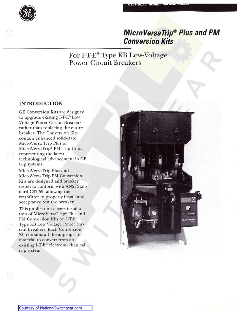
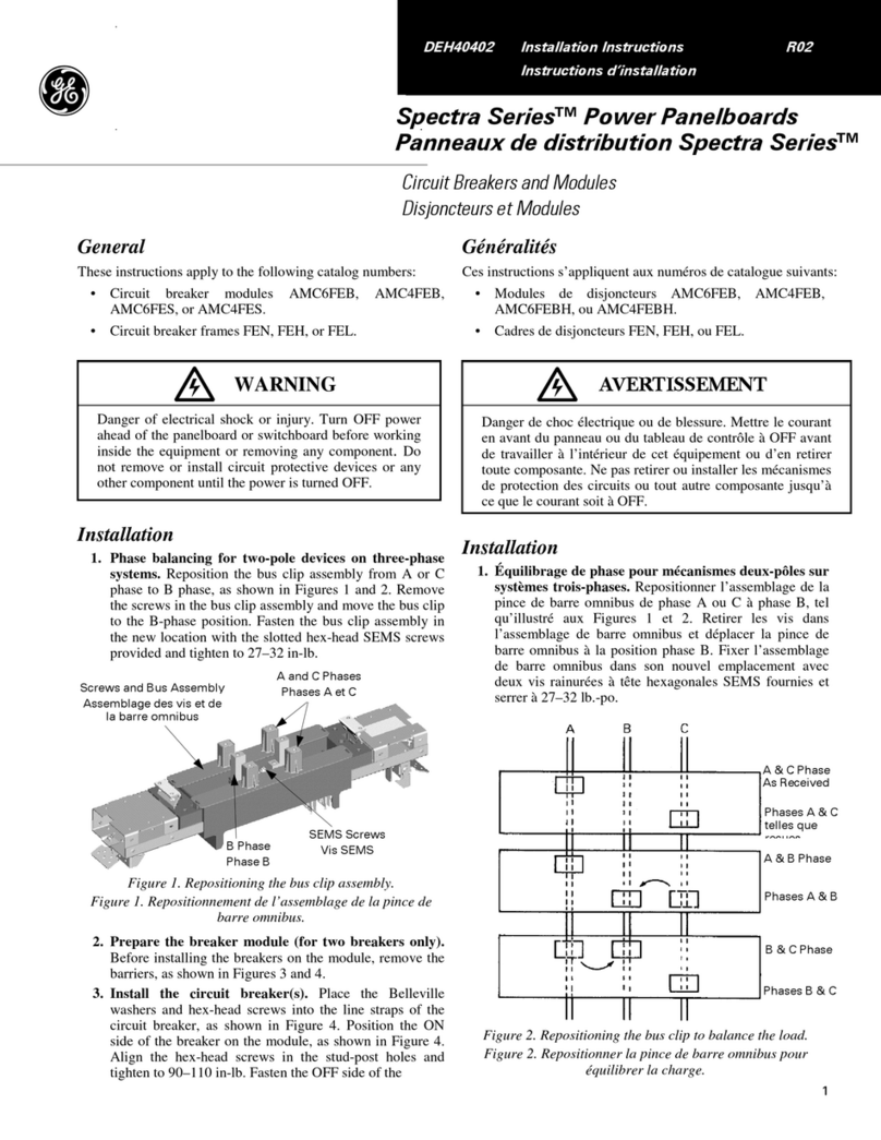
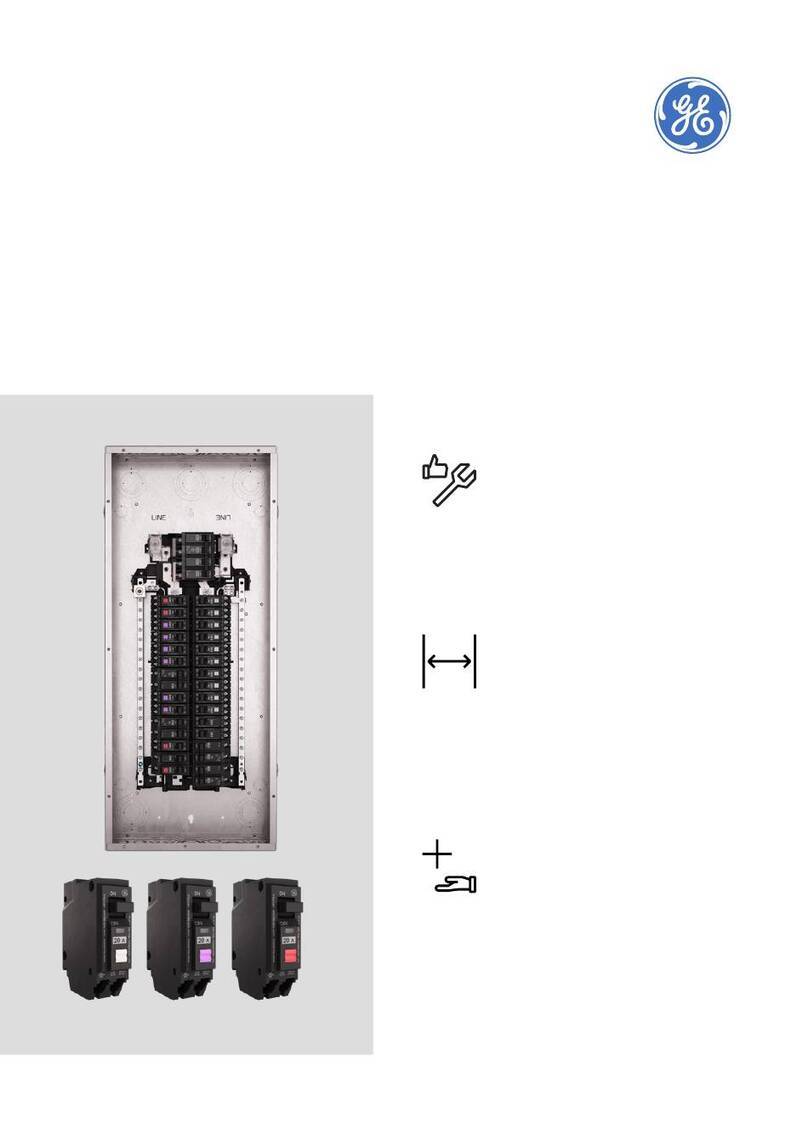
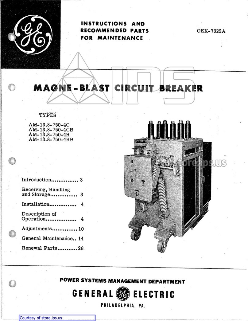
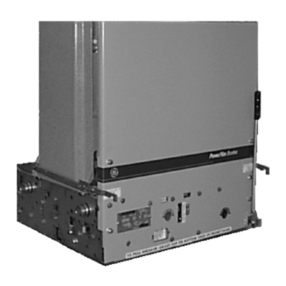
GE PVDB-28kV User manual

Vacuum Circuit Breaker
Spring Operating
Mechanism
ML-18H

~Distribution Breaker Tableof Contents-
Section 1. Introduction
1-1 Safety1-2 Maintenance
..,J
23
23
23
23
23
, 23,
23,
24
25
25
25
25
25
, 26
3
3
Section 2. Receiving, Handling & Storage 4
4
4
5
,5
5
5
.8
.8
Section 3. Description
3-1 High Voltage Compartment3-2 Bushing CulTent Transfonners
3-3 Device and Tenninal Board ,
3-4 Mechanism ,
3-5 Emergency Trip3-6 Control Circuit
Section 8. Maintenance
8-1 GeneraL8-2 SeIVice Conditions8-3 PowerVac Interrupter8-4 Contact Erosion8-5 Transfer Band Wear ;...
8-6 Insulation Tests8-7 High-Potential Test8-8 Vacuum Interrupter Integrity Test
8-9 Primary Circuit Resistance8-10 Power Factor8-11 Mechanism8-12 Primary Insulation Parts8-13 Lubrication8-14 Recommended Maintenance
11
11
11
11
11
11
12
12
Section r 4. Installation
4-1 Location and Mounting4-2 Connections4-3 Ground Connections44 Control and Secondary Wiring.
4-5 Primary Connections4-6 Inspection Before OperationSafety Precautions4-7 Slow Closing
Section 9. Repair and Replacement
9-1 Entrance Bushing Removal 27
9-2 Replacementof IntelTUpterAssemblies.27
9-3 Pin Retaining Rings 27
94 Control Switches 27
9-5 Trip Coil Replacement 27
Tools Required 27
9-6 Closing Coil Replacement 28
9-7 RenewalParts 28
Ordering Instructions 28
9-8 BreakerRemoval 28
:::>
14
14
15
15
15
Section 5. Operation
5-1 Close Spring Charging5-2 Closing Operation5-3 Opening Operation54 Trip Free Operation5-5 Control Circuit
21-:
,
,
16
16
16
16
17
17
17
17
Section 6. Measurements & Adjustments
6-1 Wipe Adjustment6-2 Emergency Trip6-3 Primary Contact Erosion Indication6-4 Contact Gap Adjustment6-5 Control Coil Plunger TravelTrip CoilClose CoilControl Switches
List of Figures
1. High Voltage Compartment2. Low Voltage Compartment-Mechanism Side3. Toggle Linkage Positions of the MI.-18H Mechanism.
4. Low Voltage Compartment-Relay Side5. Schematic ofMI.-I8H Mechanism6. Manual Charging ,7. Close Spring Gag ,8. Ratings and Adjustments9. Adjustments10. Gap MeasurementI 1. Erosion Indicator12. Trip Coil and Linkage13. Typical Wiring Diagram for MI.-I8H Mechanism14. Mechanical Adjustments and Settings15. Closing Coil and Linkage16. Bottom View of MI.-I 8H Spring Charged Mechanism,
17. Sample Operating Speed Graphs18. Vacuum Interrupter Assembly , ,
19. Travel Recorder Auxiliary Linkage ,
20. Opening Dashpot
20
20
20
Section 7: Electrical Checks
7-1 Control Power7-2 Timing7-3 Opening and Closing Speed.
20
26
List of Tables
1. Control Devicesand Voltages '
2. Summaryof Adjustmentsand Critical Dimensions ,
3. RecommendedSparePartsfor PowerVacDistribution
Breakerswith ML-18H Mechanism 29
2
~-l ReceiVIng2-2 Handling2-3 Storage
5
5
7
810
12
12
13
1517
1818
19
22
28
29
30303131

Section,. Introduction
Introduction
This manual provides the infoI"lnation needed by the
user to properly install, operate and maintain dis-
tI'ibution circuit breakers,
1-2 Maintenance
Excellent maintenance is essential for reliability and
safety of any electrical equipment. Maintenance
programs must be tlmed to the specific application, well
planned and carried out consistent with both industry
experience and mamtfacttlrer's recommendations.
Local environment must alwaysbe considered in such
programs, including suchvariables as ambient temper-
attIres, extreme moisttlre, nmnber of operations,
corrosive aunosphere or major insectproblems and any
other unusual or abusivecondition of the application.
1-1 Safety
Each user must maintain a safetyprogram for the pro-
tection of personnel, as well as other equipment, from
the potential hazards associated with electricalequipment.
The following requirements are intended to augtnent
the users safetyprogram, but NOT supplant the user's
responsibility for devising a complete safetyprogram.
The following basic industry practiced safety require-
ments are applicable to all major electrical equipment
such as switch gear or switchboards. GE neither
condones nor assumesany responsibility for practices
which deviate from the following:
One of the critical service activities, sometimes
neglected, involves the calibration of various contI"ol
devices. These monitor conditions in the primary and
secondary circuits, sometimes initiating emergenC}'
colTective action such as opening or closing circuit
breakers. In view of the vital role of these devices,it is
important that a periodic testprogram be followed. As
was outlined above, it is recognized that the intel"Val
between periodic checks will vary depending upon
environment, the type of device and the user's
experience. It is the GErecolmnendation that, until the
userhasaccrullulated enough experience to selecta test
interval better suited to the individual requirements, all
significant calibrations be checked at an interval of one
to twoyears.
I.
ALL CONDUcrORS MUST BEASSUMEDTO BE
ENERGIZED UNLESS THEIR POTENTIAL HAS
BEENMEASURED AS GROUND AND SUITABLE
GROUNDING CONDUcrORS HAVE BEEN AP-
PUED TO PREVENT ENERGIZING. Many acci-
dents have beencausedby back feeds from a wide
varietyof sources.
2.
Although interlocks to reduce someof the risksare
provided, the individual's actions while perfonning
service or maintenance are essential to prevent
accidents. Eachperson'sknowledge; mental aware-
ness; and planned and executed actions often
detennine if an accident will occur. The most iln-
portant method of avoiding accidents is for all
associatedpersonnel to carefully apply a thorough
understanding of the specific equipment from the
viewpoints of its purpose, its constnlction, its oper-
ation and the siulations which colud behazardous.
To accomplish this, some devices can be adequately
testedusing testsets. Specific calibration insU"llctionson
particluar devices typically are provided by supplied
inSU"llctionbooks
InsUlIction books supplied by manUfaCt1Irersaddress
components that wolud nonnally require service or
maintenance during the useftu life of the equipment.
However, they can not include everypossible part that
colud require attention, particIuarly over a very' long
service period or under adverseenvironments. Main-
tenance personnel must be alert to deterioration of any
part of the supplied switchgear, taking actions, as
necessaryto restore it to seI"Viceablestat1IS.
All personnelassociatedwith installation, operation and
maintenance of electrical equipment, such as power
circuit breakers and other power handling equipment,
must be thoroughly instrtlcted, with periodic retraining,
regarding power equipment in general as well as the
particluar model of equipment with which they are
working. Instrtlction books, actllal devices and ap-
propriate safety and maintenance practices such as
OSHA publications, National Electric SafetyCode (ANSI
C2), the National Electric Code, and National Fire
Protection Association (NFPA) 70B Electrical
Equipment Maintenance must be closely stlldied andfollowed.
During actllal work, supervision should auditpractices
to assureconfonnance.
Industry publications of recommended maintenance
practices suchasANSI/NFPA 70B, Electrical Equipment
Maintenance, should be careflulystlldied and applied in
eachuser'sformation ofplanned maintenance.
Someusersmayrequire additional assistancefrom GEin
the planning and perfonnance of maintenallce. GE can
be contracted to either undertake maintenance or to
provide technical assistance such as the latest pub-
lications.
3
Distribution Breaker Section,. Introduction
The perfonnance and safetyof all equipment may be by
the modification of supplied partsor their bynon-identical
substitlues. All such desigIl changesmust be submitted to
GEfor engineering approval.
The user sholud methodically keep written maintenance
records as an aid in fuUlre seIVice planning and
equipment reliability improvement. Unusual experiences
should bepromptly communicated to GE.
Section2 ReceivinQ,HandlinQ& StoraQe
2-1 Receiving
All breakersare assembledand testedat the factory. They
are shipped assembledas complete units except for the
legs. Each breakeris carefully inspectedand prepared for
shipment by worklnen experienced in the proper handling
of electrical equipment. Immediately upon receipt of a
breaker, an examination should be made for any damage
sustainedduring shipment. If injury or rough handling is
evident,a damaged claim should be filed by the receiverat
once with the transportation company and the nearest
GeneralElectric SalesOffice should benotified.
2-2 Handling
Nonnal care in handling the breaker will result in a
trouble-free installation and long lasting life,-
2-3 Storage
When the unit canbe setup immediately in itspermanent
location, it isdesirable to do so,eventhough it will not be
placed in servicefor some time. If stored outdoors, the
spaceheaters should be energized as soon aspossible to
preventcorrosion due to moisture condensationinside the
housings.
The exposed portion of the bushings both outside and
inside the top coversholud bechecked for chips or cracks
especiallynear the clamps on the top frame.
~
4

Section3. Distribution Breaker
cThe cuITent transfonners are bolted to the top frame
with bolts through each comer and must be properly
centeredaround the bushing when installed.
3-1 High Voltage Compartment
The three phases in the high voltage compartment,
Figure 1,consistof porcelain bushings,bushing current
transformers, vacuum interrupters, insulating supports,
and connection bars. 3-3 Device and Terminal Board
Panels are provided in the low voltage compartment,
Figure 2, for mounting terminal boards for C.T. and
control wiring and control devices. A cut-out with a
cover plate is provided in the floor to permit conduit
connection for external circuits.
3-4 Mechanism
The trip-free operating mechanism is motor charged
and spring operated. The action of a closingcam, (Fig.
3, 5), driven by a closing spring causesclosing of the
breaker contacts thru a toggle linkage. In closing,
energyis stored in the opening springs and the contact
wipe springs. Releaseof this energy by operation of the
trip latch causesbreakercontactsto open.
Figure 1.High Voltage Compartment
The vacuum inten"Upters, their supports and the
operating mechanismcomprise an inten"Upting module
which is essentiallythe same as the PowerVac circuit
breakerusedin Metal-CladSwitchgear.
0The bushings are clamped to the roof of the housing.
The bushing core is centered in the air-filled porcelain
and rubber gasketsseal each end. Mter the bushings
have been clamped in place no further adjustment is
necessarywhen installing the connection bars
3-2 Bushing Current Transformers
Bushing cuITenttransformers areused on thesebreakers
to provide a source of CUITentsupply for operating
protective relays. Relayingtransformersare of the multi-
ratio type having five leadswhich provide a wide range
of ratios. Ratio accuracy classification for standard
transformers are in accordance with ANSI C-57-13and
NEMA SG-4,table 3-5specifications.
Figure2. Low Voltage Compartment-Mechanism Side
Additional mechanism features shown in Figure 2, are
the open<lose and charged-<lischargedindicators; oper-
ations counter, manual close and trip pushbuttons;
auxiliary switch; and padlock on the trip function. An
optional feature is the addition of a key interlock on the
trip function.
High accuracy. single-tap metering-type current trans-
formers can also be furnished. Ratio and accuracy
classification for standard transformers of this type are
also in accordance with ANSI C-57-13and NEMA SG4
table3-5specifications.
Closing and opening operations may be controlled
electrically bya control switch on the breaker or remote
relaying. Mechanical control is provided by manual
close and trip buttons on the circuit breaker. The
closing spring maybe manually charged,and a method
for slow<losing the primary contacts is available. The
mechanismwill operate at the ac or dc voltageindicated
on the circuit breakernameplate.
Performance data in the form of ratio curves are
available for all standard transformers of standard
ratios. These are supplied in an instruction book or can
be securedfrom the SwitchgearOperation by giving the
proper references. The manual charging system(Fig. 5, View A, 3) works
directly on the cam shaftwhere a one way clutch (Fig. 5,
View A, 7) driven by a manual handle provides rotation
of the ratchet wheel. Manual pumping of the handle
advances the ratchet wheel, and the holding pawl
Bushing cuaent U"ansfonnersare mounted inside the
top frame. They are installed from underneath the top
frame and mustbeslipped over lower end of bushing.
5

Distribution Breaker Section3 Descriotion
preventscounter rotation while the handle is returning
for another stroke. Six to eight complete strokesof the
manual handle are required for one complete spring
charging operation.
The mechanismis mechanically trip-free in any position
on the closing stroke. Electrically energizingthe trip coil
while closing, after the auxiliary switch contactschange
position, will rotate the trip latch and permit the circuit
breaker to open hIlly. The linkage will reset as in a
normal open operation and the closing spring will
recharge.
Breaker Open Spring Discharged
A
:)
4. TRIP ROLLER
5. CLOSING CAM
6. TRIP LINK
7a. CLOSING TOGGLE
7b. CLOSING TOGGLE
8. PROP SPRING
9. LINKAGE RETURN SPRING
10. CLOSING ROLLER
11. PROP
12. OUTPUT CRANK
13. JACKSHAFT
14. TRIP LATCH
Note: Shading indicates fixed pivots.
Breaker Open Spring Discharged
B
Figure3. Toggle Linkage Positions of the ML-18HMechanism
(View from RightHand Side)
fi

Distribution Breaker
Section3. Description
7a.
( C) Breaker Closed Spring Discharged
DBreaker Closed Spring Discharged
7

Distribution Breaker Section3. Descriotion
Mter using the emergency u'ip, the mechanism door
,
3-5 Emergency Trip
3-6 Control Circuit
A typical ML-18H mechanism wiring diagram is shown
in Figure 13. Check the wiring diagram supplied with
the actualcircuit breakerfor itswiring.
The mechanism mounted auxiliary switch contacts not
used in the control circuit are bought out for control
and indication functions. An additional mechanism
operated, housing mounted auxiliary switch can be
provided for additional contacts.
Figure 4. Low Voltage Compartment-RelaySide
8
must beopened and the lever resetmanually to release
the tI'ip button,
A "Pull to trip" knob is provided on the outside of the
mechanism door for emergency tripping of the circuit
breaker. When the breaker is tripped by means of this
knob, a small leveron the front of the mechanismframe
is spring operated to hold the trip button depressed,so
that the trip latch cannot reset, and the breaker is
mechanically trip-free. The latch checking switch
(LCS) Fig. 14, is also held open so the closing coil
cannot be energized. Provision is made for padlocking
the lever in the operated position. As an option a key
lock can also be provided to hold the trip button
depressed, and a switch can be added for remote
indication of manualtrip.

Distribution Breaker
a_-
Section3. Descri.otion
VIEW
; l
'~'.,-' I
I
VIEW
C'1
16c
0
0101-~o II
J~l~
\1-4
_oJ
0
~-
L---
0
qj
pJ~-
J~II
'==.-
VIEWj
E
'= jVIEW
C
VIEW.
8
13, V I EW~'-V I EW
A D
Figure 5. Schematic of ML- 78HMechanism
1. CLOSE SPRING
2. CAM SHAFT
3. MANUAL CHARGE
4. CHARGING ARMS
5. RATCHET WHEEL
6. DRIVING PAWL
7. ONE-WAY CLUTCH
8. CLOSE LATCH
9. CLOSE CAM
10. CLOSE ROLLER
11. PROP
12. OUTPUT CRANK
13. CROSS SHAFT
14. BELL CRANKS
15. OPENING SPRINGS
16. WIPE SPRINGS
17. AUX. SWITCH
18. TRIP SOLENOID
19. TRIP LATCH
20. OVER-TRAVEL STOP
21. LATCH CHECK SWITCH
22. GEAR MOTOR
(Continued on next page)
9

Distribution Breaker Section3 Descriotion
\
LI
L2
/
CXRECTaoIJ
~ ROTATION PARTIAL VIEW -B
~~===~B~. D' I .D
"...~\ 21
II1II'
PARTIAL VIEW -C
6
PARTIAL VIEW -D PARTIAL VIEW -E
Figure5 PartialViewsof ML-18Mechanism
10

Section 4. Installation
adequateprotection. A poor ground maybeworsethan
no grolmd at all, since it givesa falsefeeling of safetyto
thoseworking around the equipment and may result in
lutimate lossoflife or damageto the apparatus.
General
The installation of the breaker will be facilitated by a
sllidy of theseinstnlctions and a reviewof the approved
drawings which supplement these instnlctions. The
drawings show the general arrangement, dimensions
(Fig. 8), location of foundation bolts, provisions for
conduit connections, electrical connections and other
information necessaryfor the proper installation of the
breaker. These drawings consistof the requisition sum-
mary, outline of the Imit with its operating mechanism
and housing, and the connection diagrams.
4-4 Control and Secondary Wiring
The breakeris shipEedin the closedEosition.
4-1 Location and Mounting
The tmit shotud be located so that it is readily accessible
for manual operation and inspection. Care should be
takenwhen lifting the tmit not to allowthe lifting device
to come in 'contact with the bushing. Two lifting holes
are ~rovided on the to~ of the unit for lifting ~uwoses.
The total weight of the tmit is given on the nameplate
and should be takeninto consideration when selectinga
lifting devicefor the breaker.
Concrol and bushing clUTent cransformer connections
are made inside the operating mechanism hOllsing
where suitable terminal boards are provided. Con-
nection diagramsare supplied for eachunit showing the
proper connections for the operating mechanism and
the bushing current transfmmers. All bushing cun-ent
cransformer terminal boards are shipped shorted and
grolmded. These connections sholud be changed upon
selectingthebushing ClU"I"enttransformer ratio.
Legs for the basic tmit as indicated on the outline
drawing come in 12 inch to 36 inch lengths and are
shipped separately,ready for assembly. Mter assembly,
fasten the breaker in position on its foundation. The
fotmdation should be firm and level; if it is not, shims
sholud be used tInder the motmting pad of the leg to
level the unit. The motmting bolts recommended are
0.625 inch diameter minimum (0.75 inch diameter bolt
can alsobe used) and their locations are shown on the
breakeroutline drawings.
4-5 Primary Connections
Leads should be bought down from above if possible.
Ample electrical clearance must be provided between
these leads and parts of the station, such as wall,
channels and framework. Leads sholud be properly
supported so that the breakerbushings are not subjected
to unnecessarystrains. The bushings sholud not carry
cable or bus bar strains. To avoid overheating, the
connecting leads must be of a current-<:arrying capacity
at leastequal to the maximum operating current of the
circuit which sholud not exceedthe breakerrating.
4-2 Connections
Mt~r the breaker has been located, electrical
connections can be made. Before making these,every
precaution must be taken to see that all leads to be
connectedto the tmit aredead.
Connections to the breaker are made by the bolted
connectors fastened to the ends of the bushings and
must be securelytightened to assuregood contact. All
joints mustbecleanand bright.
4-3 Ground Connections
The framework of each breakershould be permanently
grounded. The usual practice is to connect a heavy
cable to the framework and to the grolmd. Provisions
for a bolted connector is provided on the framework to
which the grolmd cablecan beattached. 4-6 Inspection Before Operation
After the unit hasbeeninstalled with all mechanical and
electrical connections completed, the following in-
spectionsand testsholud be made before operation. If
any question arises concerning the lmit during the
following inspection procedure, refer to Section 6,
Measurementsand Adjustments.
The cable sholud be able to carry 25 per cent of the
current rating of the breaker, but should not be smaller
than MIO.
Agood permanent lowresistanceground is essentialfor
All control wiresshould be run in conduit insofar asit is
practicable. Control wires must be rtm separatelyand
remote from high tension leads tmless the distance
separating the two setsof wires is sufficient to prevent
possible commtmication between them as a restut of
shortcircuits' Control wiring of adequatesizeshould be
used so that with nul operating current flowing to the
operating mechanism, the voltage acrossthe terminals
of the mechanism will be within the limits specified as
standard for the control voltage as specified on the
nameplate. It is recommended that all conduits
entering the mechanism housing be sealed off at their
entrancesto the housing.

Distribution Breaker Section4. Insta
2. Insert the closing spring gag plate (Fig. 7) by
engagingthe detentson the gagplate into the slots
on the closing spring guide. With the gagplate in
position, depress the manual close button. This
action will partially close the vacuum interrupter
contact. Do not energize the secondary control
circuit atthis time.
Safety Precautions
1. Check that the unit is properly setup and leveled
on itsfoundation.
2.
Checkthat all nuts,washers,bolts,snaprings, cotter
pins and tenninal connections are in place and
tightened.
3.
Visually inspect the circuit breaker for any signs of
damage during installation and test it for possible
grounds or shortcircuits.
4. Inspect all insulated wiring to see that it has
sustainednot damage during installation and testit
for possiblegrounds or shortcircuits.
5.
Check that all bearing surfacesof the operating and
breaker mechanisms have been lubricated with
0282A2048POO9grease.
6. Check that all points where the surfaceof the paint
has been damaged during installation are re-
painted immediately. Figure 7.Close Spring Gag
3. To manually slow-closethe breaker contacts,insert
the manual charging handle in the manual charge
slotand movethe handle up and down about 6 to 7
times until closingroller (Fig. 3, 10)isfree from the
closing cam and resting on the close prop (Fig. 3,
11).
III#'
4-7 Slow Closing
1. Manually charge the breaker closing spring using
the charging handle provided (Fig.6). The closing
spring is charged by a ratcheting mechanism that
advancesbyone ratchet tooth at a time. When the
spring isfully charged and the spring load isheld by
the closing latch the spring indicator will change
from "'DISCHGD" to "CHARGE" (Fig. 7), and a
positive snapwill be heard asthe spring travelsover
center. Mter the spring is completely charged, as
indicated above, further forcing th~ charging
handle may causedamage to the closing latch and
itsassociatedparts.
CAUI10N: With the gag plate installed, the breaker
closedand opening springscharged, the breaker canbe
tripped at full speed.
4. In the closedposition, check the erosion indicator
(Fig. 11). Checkthe insulation resistanceto ground
by connecting a megohmeter between the primary
circuit and ground. The minimum resistance
should be 10,000megohms or higher.
5.
Keepclearand pushthe manual trip push-buttonto
trip the breaker open. Check that the position
indicator shows"Open" and the operation counter
advancesone count. Removethe closing spring gag
plate.
6. Discharge any stored energy in the breaker by
successivelydepressing the manual close and
manual trip buttons. Performing theseoperations
leavesthe breaker open with the closing spring
discharged.
""
Figure 6.Manual Charging 12

.Section 4. 1~ml@tiQn- Distributi
Nex~ the following electrical checksshould be made,if
reQuired.
Electrical checking consists of electrical breaker
operation; secondary wiring high-potential testing (if
required), primary current path resistance(if required),
PowerVac interrupter high-potential testing, and
insulation resistanceto ground.
2. Perform a vacuum intemlpter integrity testto verify
the condition of the inteITUpters. Perform the test
asdescribedin Section8.
3.
Perfonn any of the above mentioned test as
required. Testdescriptions can befound in Section
8.
To check the electrical operation apply control
voltage to the circuit breaker. Check the control
voltage on the nameplate and closeand open the
breakerseveraltimesto checkelectricaloperation. 4. Leave the circuit breaker in an open and spring-
dischargedcondition after checksarecomplete.
-~
Si8
iltPWo._'
~-
~
DETAIL"B" ,'°.
s..,.
~
~
""-
..,P*bCT.J I
'=~~ DMO- 0PLAN VIEW"A. A" /
QI I'
~'25 NOTES:
1. 18.00isStandardLegHeight.ForOtherLegHeights.
(ie.12,24,30& 36) AdjustVerticalDimensions
Accordingly.
_.~
2.
09
112
G~Pod
Bushing1,3,5areConnectedtoStationarySideof
VacuumInterrupters.
"Emergency"Pull-To-TripKnobmustbeResetBefore
BreakercanbeReclosedManuallyorElectronically.
3.~
~
17S-i Rating
Upto1200A
Upto2000A
'G'DIA
3.75
4.50
Weight
2200RJs.
2500IJs.
54" ,J'
1.25-12
1.75.12
FRONTVIEW
SIDEVIEW
Figure 8. Breaker Dimensions
~
13
IDETAIL.C" ..C"J
(LegP81)

Section5 Ooeration Distribution Break
and the closing springs are charged asdescribed under
para5.1 "CloseSpring Charging". This ispossiblewhen
the breakeris in the closed position becausethe linkage
isheld in position bythe prop.
a nonnal open operation and the closing spring will
recharge as described under Close Spring Charging
(para5-1).
5-5 Control Circuit
A typical PowerVaccircuit breaker ML-18H mechanism
wiring diagram is shown in Fig. 13. Check the wiring
diagram supplied with the actual circuit breaker for its
wiring.
The close spring-<:harging-motor circuit is established
through the CL/MS switchif the closelatch is resetand
the SM/LS switch if the closing spring is discharged.
When the closing spring is charged, the SM/LS
interrupts the circuit.
5-3 Opening Operation
By either energizing the trip solenoid (Fig. 5, view B)
(18) or depressingthe manual trip button, the trip latch
(Fig. 5 viewD) (19) isrotated permitting the linkage to
collapse and the vacuum interrupter contactsto open
under the force of the wipe springs (Fig. 5,viewE) (16)
and opening springs. At the end of the opening strokea
stop hits the frame and limits overtraveland rebound.
Rotation of the cross shaft from the closed to an open
position operates the auxiliary switch (Fig. 5, view D)
(17) and interrupts the trip coil current. If the closing
spring has been recharged the linkage will be resetso
that the trip latch will fall in place on the trip roller in
preparation for another closingoperation.
If the closing spring has not been recharged, the trip
latch will be held out of position. At latch checking
switch (Fig. 5, view C) (21 ) will not closeunless the
latch is in its normal position. The contacts of latch
checking switch are in the closing circuit so that
electrically initiated closing is blocked when the trip
latch is not reset.
5-4 Trip-Free Operation
The linkage is mechanically trip-free in any location on
the closing stroke. This means that energizing the trip
coil while closing after the auxiliary switch contacts
change position will rotate the trip latch and permit the
circuit breakerto openfully. The linkage will resetasin
The close circuit is established through two normally
closed Y relay contacts, 52Y and the latch-<:hecking
switch LC, if the trip latch is reset. An auxiliary switch
contact52isalsoin serieswith the closecoil and it closes
when the breakeris open and openswhen the breakeris
closed. During acloseoperation, camrotation closesthe
SMItS contact, picking up the Y relay coil thereby
opening its contactsto intemlpt the close,coil current
and sealing it in through a normally open contact to the
close signal. The sealing prevents re-<:losing on a
sustained close command as the close signal must be
removed to drop out the Y relay, and re-establishthe
closingcircuit, therebyproviding an anti-pump feature.
The mechanism mounted auxiliary switch contactsnot
used in the control circuit are brought out for control
and indication functions. An additional breaker
operated, housing mounted auxiliary switch can be
provided for additional contacts.
5
4
2
1. WIPE SPRING
2. OPERATING ROD INSULATOR
3. EROSION INDICATOR
4. INTERRUPTER CLAMP
5. CLAMP SCREWS
6. EROSION DISK
7. LOCK NUT
8. HEXAGON PROJECTION
83
7
6
Figure 9.Adjustments
15

Distribution Breaker
.Section 6. Measurements and Adjustments
General
The ML-18H mechanism has been designed for ex-
tended intervals between maintenance. In most cases
only the wipe and gap adjustmentswill require re-setting
throughout the life of the circuit breaker. In addition to
the descriptions of the adjustments,Table 2 contains a
summaryof the settings.
6-1 Wipe Adjustment
Wipe is the additional compression of a pre-loaded
spring, used to apply force to the vacuum intelTUpter
contactsand to provide opening kick-offforce.
The wipe sholud be setasfollows:
BreakerRating
All Wipe (inches)
0.155-0.180
6-2 Emergency Trip
Readjustwhen reduced to 0.075
To adjust the primary contact wipe, close the breaker.
Refer to Fig. 14 for the following wipe adjustment
procedure.
1. Loosen but do not remove the two screws (5),
holding the intemlpter clamp (4).
6-3 Primary Contact Erosion
Indication
In the closed position, the erosion disk (5, Figtlre 11)
below the operating rod insluator is aligned with a
reference arm (4, Figtlre 11) on new intemlpters. As
contact erosion occurs, the erosion disk will move
upward from alignment with the reference arm.
When erosion reaches 0.125 inch, the PowerVac
intemlpters should bereplaced.
~
2. Check that the intemlpter clamp is loose. A light
pry at the clamp half jllllction may be required to
loosenthe wedging action of the clamp.
3.
Hold the hexagon projection (8), at the bottom of
the operating rod insluator (1 inch wrench) and
loosen the adjacent locknut (3/4 inch wrench),
item (7). Adjust by rotating the operating rod
insulator. The thread is 1/2-13 and eachulrn will
give about 0.078 inch change in primary wipe.
Screw the operating rod insulator toward the
intemlpter to increasewipe.
Do not re-adjust the alignment of the erosion indicator
exceptwhen installinganewvacuuminterrupter.
6-4 Contact Gap Adjustment
The method of measuring the contact gap is asfollows:
With the breaker in the open position, the closing
springs charged, and the closing spring gag plate
installed, applya piece of masking tape to the surfaceof
the operating rod insulator as shown in Figtlre 10.
Using a reference block,make a mark on the tape near
the top on all three poles. It is also advisableto put a
reference mark on the tapeto identify to which pole the
tapeisapplied. Removethe closingspring gagplate and
closethe breaker. Using the sameprocedure as above,
re-mark the tape. This new mark will be near the
bottom of the tape. Trip the breaker,remove the tapes
and re-apply them to a flat surface. Measure the dis-
tance between the two lines. A caliper will give an
accuratereading of the contactgap.
4.
Mter setting the contact wipes on each phase
torque the operating rod locknut (7), to 40-50foot
potmds while preventing the operating rod
insulator (2) from tttrning. Tighten the clamp
screws(5) to 10-12foot pounds. Trip the breaker
open. This procedure preventsaccidental twisting
of the operating rod of the intemtpter by loading
the contacts with the wipe springs and forcing
relative rotation to occur atthe clampinterface.
Mter adjustment, re-measurethewipe for eachphaseto
checkthe adjustment. If the wipe settingsare within the
required limits, there is an adequate contact closing
relationship betweenthe poles. Referto Figure 14,wipe.
16
A 'Pull to Trip' knob is provided on the outside of the
mechanism door for emergency tripping of the circuit
breaker. When the breaker is tripped by means of this
knob, a smallleveron the front of the mechanismframe
is spring operated to hold the trip button depressed,so
that the trip latch cannot reset, and the breaker is
mechanically trip-free. The latch checking switch
(LCS) is also held open so the closing coil cannot be
energized. Provisionis made for padlocking the lever in
the operated position. As an option a key lock can also
beprovided to hold the trip button depressed.
Mter using the emergency trip, the mechanism door
must be opened and lever resetmanually to releasethe
trip button.
When properly adjusted, the lever will move acrossthe
faceof the trip button just asthe breakertrips. When it
is holding the button depressed, the trip latch must
not permit the mechanismto close. Afine adjustment of
the trip latch adjusting nut may be required to insure
this,SeeTable 2,adjustment#1 and Fig. 12.

.Section 6. MeasurementsandAdjustments
Sequenceof operation of dual trip coilsisdetermined by
thecustomer.
Dimension G: The gapsmust bebetweenthe 0.00 inch
maximum at the centerpole and 0.54inch minimum at
the outer poles. It is not necessarythat all readings
correspond. A properly adjusted breakerwill havemore
gap and wipe on the center pole than on the outside
poles.
Close Coil
With the closing spring discharged,operate the plunger
in the same manner described above for the trip coil.
Make certain that the pltmger movesfreely over its nul
stroke in the coil, seeFigllre 15.
The closecoil and trip coil plunger dimensional checks
are made in the operating mechanism which is
accessiblefrom the bottom. To accommodate these
checks,the breaker should be lllrned on its right side
resting on two-by-fourwood blocks. DO NOT use the
portable breakerlift trIlck.
6-5 Control Coil Plunger Travel
Trip Coil
With the breaker in the open position and the closing
spring in the charged position, make certain that the
trip linkage and trip shaft move freely over the full
plunger travel, (Fig. 12).
Control Switches
There are three switch locations on the ML-18H
mechanism (SeeFigllre 14). The CL/MS closing latch
monitoring switch (13), is to the rear of the ratchet
wheel and is operated from the closing latch. The
SM/LS spring motor limit switches (11) control the
spring charging motor and the anti-pump relay. The 52
charge switch,which is in the samelocation canbeused
for remote indication of the charged condition of the
spring. The L/C latch checking switch (12), monitors
the position of the trip latch.
The switchesare adjustedasdescribed in Table 2 Items
8and 9.
Some breakers due to the customers application are
equipped with two trip coils (optional), (Fig. 12).
,
-rMASKING TAPEIi
10PENPOSITIONI
"'"'
~.LOCK
O'EN
CLOSED -
5.12
_,,~/..-DIAL INDICATOR
f 01 ~
-
WASKINCTAPE:\
,
~,
Figure 10. GapMeasurement
'-
17

Distribution Breaker Section6. MeasurementsandAdjustments
~
.,..-OPERATINC
~OD
.I l
2
EROSION DISC.
5
6
3
-;r::zr;::;..rL OCKNUT
=~\~~EROSION
INDICATOR
REFERENCE
ARM 4
~I --
1. HEXAGON PROJECTION
2. OPERATING ROD INSULATOR
3. WIPE SPRING
4. EROSION INDICATOR
5. EROSION DISK
6. WIPE INDICATOR
(Shown in closed position with no contact erosion)
Figure 11. Erosion Indicator
~CTUATOR ARMTRIP ARM
ACTUATOR ARM I'~ ~~
IP ARM [TRIP PIN
(:\ I e ADJUSTINGNUT~
~ I LOCKING CLIP,
(BENDCORNERIAGAINST
TRIP PIN ADJUSTING NUT)
LOCKING (BENDCORNERAGAINST
CLIP ADJUSTINGNUT)
:;~~- ADJUS TING NUT
"T~
L.ftt -
COil ASH:--
DEPRESS
PLUNGER lTO.25~:8ggL
GAP ~~lL
PLUNGI:-j~~~~~~1-
BASE 1
STOPBRACKET---1
-tkl ~
--COIL ASH.
rDEPRESS PLUNGER
-1- TO.25~:8~GAP
tb-r§~;§::::PLUNGER BASE
TRIP COIL #"2
TRIP COIL"
Figure 12. TripCoil and Linkage
18

Distribution Breaker
Section6. MeasurementsandAdjustments
c
, ,
I ,
, I
...>- 1~!In [8J I«' N uNU N UNU ,
«' lEJu, IEJ", Ejl", -' (iJv;ID '" U ,
> , -.,- fI -r
1~---:!1;-'...-no- -N -;;;,~v-" :
, ,
I ~I , , ,~
1 lEJini ., 0-1 ,-
1 ~ In , no cr, N I\J ::NUlcr, Nix IJ I ..cr ,l9Jnl ol9Jnl 0 ~",II- I cr
In I ~ [QjlnuT-oI, ~ ~~'--" __Ii!
I- ' I '" U , , n .0- ~ ~ v-;::T'"
LoJ , o I r ,
11:","" -' .»- 1-0 ,
UJocr " In~~-, cr LIn-"" ~NX: LoJO"'Z I"
U=-' ,",,"'In ",,-NO '=-
Z ~
-I n~ I Q I
I r<r1:::~ '
I ~"... I
: l-;;c::J;;-T :
, ,
rJIn ~I~ I, -' EO,
n, " " I- ,.0-
'" "",,'" "=N -'!PI'" o , "
cr. ~ 1n1!!1J., .I;J.,2: ,"
D~ "" "" ~=. 4
, -N -N- N II
, ,
' -,
"
«
~
IEJ~ I~-J
"'
<I ..
"'IQ:1NI a
>=lnIc'"
~~
"'"
--
" ~
<I -
",...,N ! a
>~.,~m
~n ~
--
n
a ...
"'1Q:1~1 a
~'=W'c'"
~~
-N
:--N
<I -
<I ~N Ia
~~"'~<t
I tn 0-0;'II..,.-:!'!oj -
0:« N
<IC) N <t
~ Q.~[g;J",I~'"
In~ '" ~
Om
»
% ~
u Z
1-0 -
«I- III
-I 0
~IIIZ UO
111- "'Z .
I-a: a:« XI-
~~ 2: U'"
~III 1111: 1-111
III '-0-",
o.~.",U ~~
OZa: W III
-III>'" '"
..I"'" "'111~-
-0<1 ~O Z
0-1'" ~-I-=
UUa: U ~U
m.. u-
"'III «0...«
"'WI- -I'" X..I
<1"'- "'Z"'«::I ~- z
-ILoJU CI X'"
"'-I1r ~I- UX
a:",- 2:"'.->
~ :o:. «
~ Gol/O..IO
ZX'" I \oj
-UI/O -<1 0.1/0
1r-0'" -0
~X-I ZZ a:-I
I/O> «O'-U
~I..1 !III'" '" "'I U
on on In...
N
a
~
...m
a-
4"aU4"-4
C~-JCC
rp ' I "1
~4"...o-am
0.
,E. -c -= ~
0-
«
~
...'" @- '0
«u U-u
U-«.«UUUID
"""'>->->U»-
lOTI I I I I I I I I
l!:J-N"'..",n'O'O
&
~
~~~
I- II
-N
J~.J
~'C'~ ~
I-U- 0
~I
0
m
tAl
In
.0
a..J .
a:U>-
...J
~.a ~g~ ~..J j..J ~0>- 0-&0- r 1:
0:: " "'W1- -
-N -N
00 In B
1& tAl a: a:
In~ a:o
~"'H"";:;
N e
~
~
Z .III
-0 ~
III ~ iii Z
-0. ~-
III ~ ~ ~
:1:,.. Z ~ 0.
UO~ -Z I/!
Z I-%~u ~ ~
-_N -.~-1111 ~-,. Z
~O cnmo Z"-1-"' ~ " ...a: -1 U I -1 cn
O~ (!)o.U "':' 0
"'-'0 Z~ Z~ (!)-II.-1
"'--I G «a: -uo ~- u
X ~ '" -N ".
o._~ .u 0 I/! ~ ~ I ~ Z
-zcn I--~ 0.-« '"
---II--N iii --C[ cn -:1:.
--ILO ZXZ U> >0
"'~.. I O. OUU ~cn", '"
.,- "'00 -G .x: I- OI-Z O~
~ a:,. II.U ~
"'I ~ --it-- ~ r Z Z :I: -1 -1 ..~ I/! ~
3:1 '.,UI I >- U -1 :l:1-1L 0:1:
...1 O~ I-Z:' UZU>-,U
~ -N ~ Zo. <t",... 1-0 U
(!) --""""-UJOO U>UI -'X -UZ ..
a: "~<ta:~~C[a: ~(!) ~ WI/!-'
-r ""aJmmmmm ~~ ~ Z"' ;C 1---1
0 ~~,.=-=-=-~~ ~IiIZ ~O- -~ U:."""" UJN -I .'",--"'","'~"",
Z ..-N"'.."" U 00. U «I/! <nl/!U -OZ I--
0' 0 rn1 [8] " -N ~ I. (/) iii 0 000 1:1--'" Z...
-T ~ -N -.~-1 -'-'-' -00. O~
I- I I/! , Oo-N .W mu UUQI -11:0 UC[
U NN~~C[N U/ ~
w ~du uu~~~u UI/!-' ~ ~ I- ",!VI
Z N ZZ -'U~~~... Uo- '" 3: -' .
Z nu do, , I , , r NI-,o .-.'\..-4g ..a ~I'I~0 N '" -N.., n '0 '" ., uu -N -N Ztv -J tv" tv:r
U .""'In., U
0-
ct
So--m>~~I I I I
--'-NN
_f11
~t"
~I~~
N-
C~
[Q2].!.c:.
\.,.I Figure 13. Typical Wiring Diagram for ML-18HMechanism
19

Distribution Breaker -Sectiofl.l Electrical Checks -
7-1 Contro/Power
After the breaker has been operated severaltimes with
the manual charging lever and the mechanism
adjustmentsare checked as described,the closed circuit
operating voltagesshould be checked at the close coil,
trip coil, and motor terminals. Control power for
electrical operation of the breakermaybefrom either an
alternating or direct current source. The operating
ranges for the closing and tripping voltagesas given on
the breakernamep)ate,areasfollows:
7-2 Timing
Timing maybe checked by monitoring control circuit
voltage and using no more than six volts DC and one
ampere through the vacuum interrupter contact to
indicate closedor open condition. Typical time ranges
varywith coilvoltage but nominal valuesare:
Initiation of trip signal to contact parting
35-45Milliseconds (5 cycle)
25-30Milliseconds (3 cycle)
Rated
Nominal
Voltage
Trip
Circuit
Min. Max.
Initiation of closesignalto contact closing
45-75Milliseconds (DC voltages)
35-65Milliseconds (AC voltages)
Closeor
Motor Circuit
M in. Max.
48DC
125DC
250DC
38
90
180
56
140
280
28
70
140
56
140
280
Timing can be accomplished by most travel recorders.
In some cases,additional linkage and a transducer are
required. SeeFigure 18. This isavailable from GE. See
RenewalPartsManual.
120AC
240 AC 104
208 127
254 Captrip req'd
Captrip req'd
208-254
Trip-free operation may be checked by applying a
simultaneous closeand trip signal and a minimum re-
close operation may be checked by tripping a charged
breakeropenwhile maintaining a closesignal.
Instantaneousre-closetime* 100-150Milliseconds
If the closedcircuit voltage at the tenninals of the coil or
motor does not fall in the specified range, check the
voltage atthe sourceof powerand line drop betweenthe
powersourceand breaker.
*Time from application of trip signal and close
signaluntil breakeropensand re-closes.
When two or more breakers operate from the same
control power source are required to close simul-
taneously,the closedcircuit voltage at the closing coil or
motor of each breaker must fall within the specified
limits.
7-3 Opening and Closing Speed
The opening speed is modified by moving the speed
adjusting nuts on the opening spring assemblies. A
change in the opening speed affectsthe closing speed.
Referto Figure 17.
The
operating speedsareasfollows:
O~eration FeetPerSecond
Open 5.0 nominal, 4.5 minimum
Close 3.5nominal, 4.0 maximum
Table 1.Control Devices and Voltages
Nominal
Control
Voltage
48 VDC
125 VDC
250 VDC
120 VAG
Ch~ge Motor Close Coil
Part No.
0177C5050GOO6
0177C5050GOO4
0177C5050GOO5
0177C5050GOO4
Range
36-56
90-140
180-280
104-127
Part No.
0209B8103GOO8
0209B8103GOO9
0209B8103GO10
0209B8103GO11*
Range
36-56
90-140
180-280
104-127
Range I
28-56 I
70-140 I
140-280 I
(Cap. trip) I
(Cap. trip)
208-254
Part No.
(5 cycle)
0209B8104GOO1 .
0209B8104GOO2
0209B8104GOO3
0209B8104GOO4
Trip Coil
Part No.
(3 cycle)
0282A8104GOO1
0282A8104GOO7
02828104GOO6
020988104GOO4
240VAC 0177C5050GOO5
0- 208-254 0209B103GO12* 208-254 0209B8104GOO4 0209B8104GOO4
* With rectifier
20

,...
~
V.I. STOP (CENTER)
SEE TABLE 2 -ITEM 7
Figure 14. Mechanical Adjustments and Settings
(Continued on next page)
c
91
This manual suits for next models
1
Table of contents
Other GE Circuit Breaker manuals

GE
GE AK-2-15 User manual

GE
GE MicroVersaTrip Plus User manual

GE
GE CB Watch 3 User manual

GE
GE GL 311 F3/4031 P/VE User manual

GE
GE Power-Break TSUV1 User manual

GE
GE AM-4.16-250-6 User manual

GE
GE AKR Series Configuration guide

GE
GE Power Break II User manual

GE
GE A Series Pro-Stock THQB User manual

GE
GE MicroVersaTripPlus AK-50 User manual
Popular Circuit Breaker manuals by other brands

Vertical Power
Vertical Power VP-X Pro Installation and operating manual

Doepke
Doepke DRCCB 5 Series Installation and operating instructions

Siemens
Siemens 3WN6 operating instructions

Eaton
Eaton DIL-11-PI Series Instruction leaflet

Schrack
Schrack BES2 Series operating instructions

CHINT
CHINT NB1-63 Series User instruction