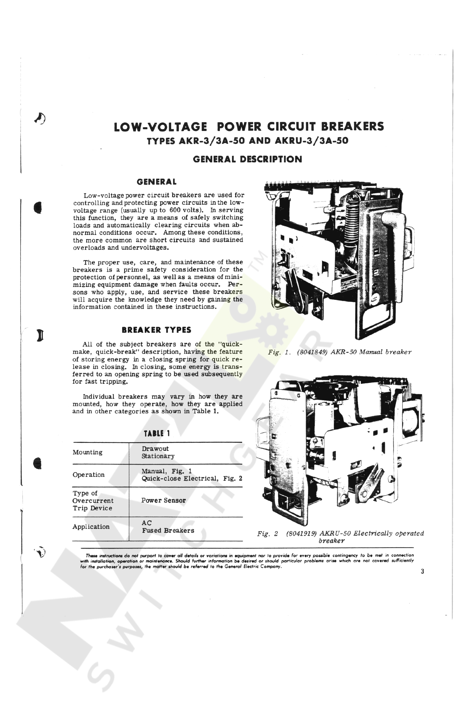
GE AKR-3-50 User manual

CONTENTS
Page
GENERAL
DESCRIPTION
General
.
Breaker
Types
Mounting
Fused
Breakers
.
..
Breaker
Ratings
.
.
.
.
Breaker
Description
.
3
3
3
4
4
4
4
5
RECEIVING
,
HANDLING
,
AND
STORAGE
Receiving
and
Handling
Storage
5
5
5
BREAKER
OPERATION
Putting
the
Breaker
in
Service
Dr
aw
out
Breakers
Breaker
Insertion
(
Fig
.
3
)
Breaker
Withdrawal
Stationary
Breakers
Pre
-
service
Check
Operating
the
Breaker
Manual
Closing
Electrical
Closing
Opening
the
Breaker
Interlocks
Closing
Spring
Interlock
(
Figs
.
6
A
and
6
B
)
Racking
Mechanism
Interlocks
(
Fig
.
8
)
.
.
Optional
Interlocks
Accessories
Shunt
Trip
Undervoltage
Device
Static
Time
-
delay
Undervoltage
Electric
Lockout
Device
Auxiliary
Switch
Bell
Alarm
*
....
5
)
5
5
7
7
8
8
8
10
10
10
10
11
11
12
12
13
13
\
(
)
13
14
14
15
BREAKER
MAINTENANCE
Safety
Precautions
General
Arranging
the
Breaker
for
Slow
Closing
.
..
Lubrication
.
'
Replacement
and
Adjustment
of
Components
and
Accessories
Mechanism
(
Figs
.
12
,
13
,
and
14
)
.
.
.
.
Mechanism
Replacement
(
Figs
.
15
and
16
)
Latch
Adjustment
Manual
Handle
Adjustment
Contact
Maintenance
Contact
Replacement
(
Fig
.
17
)
Contact
Adjustment
Components
and
Accessories
.
.
.
Auxiliary
Switch
(
Fig
.
18
)
Shunt
Trip
and
Undervoltage
Device
(
Figs
.
19
and
20
)
Maintenance
of
Static
Delay
Device
for
Undervoltage
(
Figs
.
21
and
22
)
Electrical
Control
Components
‘
..
Bell
Alarm
/
Lockout
(
Fig
.
26
)
.
..
Drawout
Mechanism
and
Interlocks
AKRU
-
50
Fused
Breaker
Fuse
Replacement
..
Open
Fuse
Lockout
Device
(
Fig
.
32
)
Power
Sensor
Overcurrent
Trip
Device
False
Tripping
Caused
by
Faulty
Ground
Fault
Operation
Testing
Current
Sensors
Replacement
Magnetic
Trip
Device
(
Figs
.
33
and
38
)
Selective
Tripping
Time
-
current
Curves
15
15
15
16
16
16
18
19
19
19
19
20
)
21
21
22
24
25
27
28
29
29
31
31
34
I
34
i
34
36
36
37
,
38
Courtesy of NationalSwitchgear.com

/
)
LOW
-
VOLTAGE
POWER
CIRCUIT
BREAKERS
TYPES
AKR
-
3
/
3
A
-
50
AND
AKRU
-
3
/
3
A
-
50
GENERAL
DESCRIPTION
GENERAL
Low
-
voltage
power
circuit
breakers
are
used
for
controlling
and
protecting
power
circuits
in
the
low
-
voltage
range
(
usually
up
to
600
volts
)
.
In
serving
this
function
,
they
are
a
means
of
safely
switching
loads
and
automatically
clearing
circuits
when
ab
-
normal
conditions
occur
.
Among
these
conditions
,
the
more
common
are
short
circuits
and
sustained
overloads
and
undervoltages
.
The
proper
use
,
care
,
and
maintenance
of
these
breakers
is
a
prime
safety
consideration
for
the
protection
of
personnel
,
as
well
as
a
means
of
mini
-
mizing
equipment
damage
when
faults
occur
.
Per
-
sons
who
apply
,
use
,
and
service
these
breakers
will
acquire
the
knowledge
they
need
by
gaining
the
information
contained
in
these
instructions
.
BREAKER
TYPES
l
All
of
the
subject
breakers
are
of
the
"
quick
-
make
,
quick
-
break
"
description
,
having
the
feature
of
storing
energy
in
a
closing
spring
for
quick
re
-
lease
in
closing
.
In
closing
,
some
energy
is
trans
-
ferred
to
an
opening
spring
to
be
used
subsequently
for
fast
tripping
.
Fig
.
1
.
(
8041849
)
AKR
-
50
Manual
breaker
Individual
breakers
may
vary
in
how
they
are
mounted
,
how
they
operate
,
how
they
are
applied
and
in
other
categories
as
shown
in
Table
1
.
TABLE
1
Drawout
Stationary
Mounting
t
Manual
,
Fig
.
1
Quick
-
close
Electrical
,
Fig
.
2
Operation
Type
of
Overcurrent
Trip
Device
Power
Sensor
AC
Application
Fused
Breakers
Fig
.
2
(
8041919
)
AKRU
-
50
Electrically
operated
breaker
‘
V
Thesm
instructions
do
not
purport
to
cover
all
details
or
variations
in
equipment
nor
to
provide
for
every
possible
contingency
to
be
met
in
connection
wrth
installation
,
operation
or
maintenance
.
Should
further
information
be
desired
or
should
particular
problems
arise
which
are
not
covered
sufficiently
for
the
purchaser
'
s
purposes
,
the
matter
should
be
referred
to
the
General
Electric
Company
.
3
Courtesy of NationalSwitchgear.com

GEK
-
7310
,
Power
Circuit
Breakers
(
Short
circuit
ratings
vary
with
the
system
voltage
on
which
they
are
applied
and
whether
they
are
equipped
with
direct
-
acting
instantaneous
over
-
current
trip
devices
.
See
Table
2
.
MOUNTING
v
Most
breakers
produced
are
of
the
"
drawout
”
type
.
These
breakers
are
equipped
with
features
which
make
them
easy
to
install
in
or
withdraw
from
their
associated
switchgear
equipment
.
These
features
are
a
racking
mechanism
(
which
facilitates
inserting
and
withdrawing
the
breaker
unit
)
and
pri
-
mary
and
control
power
disconnects
which
connect
and
part
automatically
.
Inter
locking
devices
are
included
.
Drawout
breakers
of
the
same
rating
and
type
are
interchangeable
in
their
various
locations
in
the
equipment
.
This
helps
breaker
maintenance
in
that
spare
breakers
can
be
"
plugged
in
"
while
breakers
are
being
inspected
or
serviced
.
The
"
stationary
"
breakers
are
designed
to
be
mounted
on
a
framework
or
panel
,
with
mechanical
fasteners
being
used
to
secure
the
breaker
frame
and
make
power
connections
.
If
control
power
con
-
nections
are
needed
,
a
suitable
terminal
board
is
supplied
.
TABLE
2
Rated
Maximum
Voltage
60
Herte
,
AC
Three
-
phase
Short
-
circuit
Rating
Without
Instantaneous
Trips
With
Instantaneous
Trips
*
)
)
42
,
000
amps
50
,
000
amps
50
,
000
amps
42
,
000
amps
50
,
000
amps
65
,
000
amps
635
508
254
BREAKER
DESCRIPTION
Knowledge
of
how
the
breaker
is
designed
and
how
it
operates
will
enable
the
purchaser
to
make
proper
use
of
the
breaker
and
to
avoid
mistakes
in
its
operation
.
Specific
directions
on
adjustments
and
maintenance
procedures
will
be
treated
later
.
FUSED
BREAKERS
The
three
main
functional
components
of
a
breaker
are
its
mechanism
,
an
assembly
compris
-
ing
the
conductive
members
,
and
the
interrupter
.
Fused
breakers
are
given
the
extra
letter
"
U
"
in
their
model
identification
number
.
Type
AKRU
breakers
are
not
interchangeable
with
standard
gen
-
eral
-
purpose
drawout
breakers
since
their
enclos
-
ures
must
be
modified
to
provide
the
extra
space
required
for
the
fuses
.
(
)
The
mechanism
unit
is
designed
to
receive
en
-
ergy
,
store
it
,
and
later
(
when
called
upon
to
do
so
)
deliver
it
to
close
the
breaker
'
s
contacts
.
It
must
be
able
to
reverse
its
commitment
to
close
the
breaker
at
any
point
upon
the
activation
of
an
auto
-
matic
trip
device
(
i
.
e
.
,
be
"
Trip
-
Free
"
)
.
Finally
,
it
also
must
be
able
to
trip
open
a
closed
breaker
quickly
enough
to
minimize
arc
erosion
and
in
such
a
manner
as
to
effect
proper
arc
transfer
to
the
arc
runner
.
All
fused
breakers
are
equipped
with
an
opened
fuse
lockout
device
(
OFLO
device
)
.
This
automa
-
tically
trips
the
breaker
open
when
any
of
the
three
fuses
open
.
It
also
latches
the
breaker
in
the
opened
position
until
a
resetting
device
is
manually
oper
-
ated
.
This
should
not
be
done
until
the
expended
fuse
is
replaced
.
This
arrangement
eliminates
the
possibility
of
allowing
the
circuit
to
have
only
one
phase
energized
.
The
current
-
carrying
members
of
the
breaker
are
assembled
on
the
back
frame
,
which
provides
the
mechanical
support
required
and
also
the
in
-
sulating
structure
needed
.
The
conductive
mem
-
bers
are
the
studs
for
external
connections
,
mova
-
ble
and
stationary
contact
sets
,
pivots
for
the
mov
-
able
contacts
,
and
provision
for
mounting
the
cur
-
rent
transformers
.
BREAKER
RATINGS
Type
AKR
-
50
breakers
are
1600
-
ampere
frame
size
breakers
.
This
represents
the
maximum
con
-
tinuous
current
they
may
carry
.
This
current
value
is
modified
by
the
rating
of
the
overcurrent
trip
device
with
which
the
breaker
is
equipped
.
The
lowest
available
rating
of
the
Power
Sensor
trip
device
is
200
amperes
.
As
to
voltage
ratings
,
the
breakers
may
be
ap
-
plied
up
to
600
volts
,
ac
.
t
The
interrupter
components
are
,
in
addition
to
the
arcing
contacts
,
the
arc
runners
mounted
on
the
back
base
and
the
removable
arc
quencher
assem
-
blies
.
In
addition
to
these
basic
components
,
a
breaker
may
be
equipped
with
any
combination
of
many
ac
-
cessories
and
interlocking
devices
.
4
Courtesy of NationalSwitchgear.com

Power
Circuit
Breakers
,
GEK
-
7310
RECEIVING
,
HANDLING
,
AND
STORAGE
0
RECEIVING
AND
HANDLING
1
.
The
breaker
should
be
carefully
protected
against
condensation
,
preferably
by
storing
it
in
a
warm
dry
room
,
since
water
absorption
has
an
ad
-
verse
effect
on
the
insulation
parts
.
Circuit
break
-
ers
for
outdoor
switchgear
should
be
stored
in
the
equipment
only
when
power
is
available
and
the
heaters
are
in
operation
to
prevent
condensation
.
Each
breaker
is
carefully
inspected
and
packed
before
shipment
.
Immediately
upon
receipt
of
the
circuit
breaker
,
an
examination
should
be
made
for
any
damage
sustained
in
transit
.
If
damage
or
rough
handling
is
evident
,
a
damage
claim
should
be
filed
immediately
with
the
transportation
company
and
the
nearest
General
Electric
Sales
Office
should
be
notified
.
2
.
The
breaker
should
be
stored
in
a
clean
lo
-
cation
free
from
corrosive
gases
or
fumes
.
Par
-
ticular
care
should
be
taken
to
protect
the
equipment
from
moisture
and
cement
dust
,
as
this
combination
has
a
very
corrosive
effect
on
many
parts
.
i
It
is
expected
that
due
care
will
be
exercised
during
unpacking
and
installation
of
the
breaker
so
that
no
damage
will
occur
from
careless
or
rough
handling
,
or
from
exposure
to
moisture
or
dirt
.
Check
all
parts
against
the
packing
list
to
be
sure
that
no
parts
have
been
overlooked
.
CAUTION
:
IF
THE
BREAKER
IS
STORED
FOR
ANY
LENGTH
OF
TIME
,
IT
SHOULD
BE
INSPECTED
PERIODICALLY
TO
SEE
THAT
RUSTING
HAS
NOT
STARTED
AND
TO
ASSURE
GOOD
MECHANICAL
CON
-
DITION
.
SHOULD
THE
BREAKER
BE
STORED
UNDER
UNFAVORABLE
AT
-
MOSPHERIC
CONDITIONS
,
IT
SHOULD
BE
CLEANED
AND
DRIED
OUT
BEFORE
BEING
PLACED
IN
SERVICE
.
STORAGE
It
is
recommended
that
the
breaker
be
put
into
service
immediately
in
its
permanent
location
.
If
this
is
not
possible
,
the
following
precautions
must
be
taken
to
insure
the
proper
storage
of
the
breaker
:
BREAKER
OPERATION
I
screw
is
turned
in
an
internally
threaded
trunnion
supported
by
a
centrally
located
crank
on
the
crank
-
shaft
.
The
power
screw
,
or
jackscrew
,
is
turned
by
means
of
an
external
handle
in
the
form
of
a
crank
.
This
has
,
on
its
end
,
a
square
socket
which
will
engage
the
square
end
of
the
power
screw
in
the
breaker
.
A
sliding
cover
in
the
escutcheon
must
be
moved
aside
so
that
the
handle
may
engage
the
screwshaft
end
.
Turning
the
crank
handle
in
a
clockwise
direction
moves
the
breaker
into
the
con
-
nected
position
.
The
reverse
of
this
causes
the
breaker
to
move
out
.
PUTTING
THE
BREAKER
IN
SERVICE
DRAWOUT
BREAKERS
The
mechanism
used
to
provide
th
6
mechanical
force
required
to
overcome
the
resisting
force
of
the
disconnects
on
Type
AKR
breakers
is
mounted
on
the
breaker
rather
than
in
the
drawout
enclosure
.
This
mechanism
is
referred
to
as
the
"
drawout
”
mechanism
or
the
"
racking
"
mechanism
.
It
is
a
unit
sub
assembly
and
can
be
added
to
a
completely
assembled
breaker
without
doing
any
disassembly
work
on
the
breaker
.
«
BREAKER
INSERTION
{
FIG
.
3
)
This
drawout
mechanism
consists
of
a
crank
-
shaft
and
a
power
screw
which
operates
it
.
Rigidly
fastened
to
each
end
of
the
crankshaft
is
a
crank
arm
having
an
open
slot
which
engages
a
fixed
pin
in
the
equipment
enclosure
.
As
the
crankshaft
ro
-
tates
,
the
crank
arms
,
acting
on
the
stationary
pin
,
cause
the
breaker
to
move
with
respect
to
the
breaker
enclosure
.
The
crankshaft
is
driven
as
the
power
The
procedure
for
inserting
a
breaker
into
its
drawout
enclosure
is
as
follows
:
1
.
Before
inserting
the
breaker
,
apply
a
light
,
even
coating
of
D
50
H
47
grease
to
the
silver
-
plated
bars
in
the
enclosure
which
engage
the
primary
dis
-
connects
of
the
breaker
.
JL
5
Courtesy of NationalSwitchgear.com

GEK
-
7310
,
Power
Circuit
Breakers
5
.
Extend
the
second
rail
.
6
.
Align
the
pins
on
the
breaker
with
the
slots
in
the
rails
and
carefully
lower
the
breaker
,
allow
-
ing
the
pins
to
enter
their
slots
.
Make
sure
the
pins
go
all
the
way
down
to
the
bottom
of
the
slots
;
re
-
move
the
lifting
device
.
7
.
Make
sure
the
breaker
is
open
by
pushing
in
the
trip
button
.
While
holding
in
the
trip
button
,
move
the
sliding
cover
aside
and
then
engage
the
racking
handle
.
)
8
.
If
it
is
possible
to
turn
the
handle
in
a
counter
-
clockwise
direction
,
do
so
until
the
stop
is
reached
and
remove
the
handle
.
If
the
handle
does
not
turn
,
remove
it
.
This
step
is
taken
to
align
the
arms
on
the
ends
of
the
racking
shaft
so
that
they
will
engage
the
pins
in
the
housing
.
If
the
racking
mechanism
has
not
been
operated
while
the
breaker
is
out
of
the
enclosure
,
the
arms
will
be
in
the
right
position
to
engage
the
pins
and
this
step
will
notbe
necessary
.
9
.
Make
sure
that
latches
on
the
ends
of
the
ex
-
tended
rails
are
in
the
unlatched
position
,
and
by
pushing
on
the
breaker
,
roll
it
as
far
as
it
will
go
into
the
enclosure
.
10
.
Put
the
latches
on
the
ends
of
the
rails
into
their
locked
position
.
)
11
.
Push
in
on
the
trip
button
,
move
the
sliding
cover
to
the
right
,
and
engage
the
racking
handle
.
1
.
Spreader
2
.
Drawout
Rail
3
.
Breaker
Rail
Pins
4
.
Slots
in
Rail
5
.
Trip
Button
6
.
Racking
Shaft
Arms
7
.
Housing
Racking
Pin
8
*
Rail
Latch
Link
9
.
Racking
Position
Indicator
10
.
Movable
Inner
Housing
12
.
Rotate
the
handle
clockwise
.
After
about
five
revolutions
,
the
breaker
will
be
in
the
test
position
.
The
indicator
in
the
left
upper
side
of
the
compart
-
ment
will
show
when
this
position
is
reached
.
If
the
control
circuits
are
energized
and
the
breaker
is
electrically
operated
,
the
motor
will
run
when
the
secondary
disconnects
engage
.
This
will
occur
on
about
the
third
turn
of
the
handle
.
The
motor
will
run
,
charging
the
closing
spring
,
until
the
cut
-
off
switches
are
actuated
.
Fig
.
3
.
(
8041582
)
Inserting
the
breaker
2
.
Position
the
breaker
in
front
of
the
cubicle
intended
to
receive
it
and
engage
the
lifting
device
.
A
special
"
spreader
"
is
provided
as
shown
in
Fig
.
3
.
The
hooks
of
the
spreader
are
placed
in
the
forward
square
-
shaped
holes
in
the
breaker
side
sheets
for
standard
breakers
,
and
in
the
holes
near
-
est
the
back
for
AKRU
fused
breakers
.
13
.
In
the
test
position
,
the
secondary
discon
-
nects
,
which
carry
the
control
voltage
,
are
con
-
nected
;
however
,
the
primary
disconnects
,
which
connect
the
power
circuits
,
are
still
widely
separ
-
ated
.
At
this
point
,
electrical
control
devices
on
the
breaker
may
be
operated
for
the
purpose
of
testing
.
)
I
3
.
Open
the
door
of
the
breaker
enclosure
,
and
unlatch
and
pull
forward
one
of
the
rails
in
the
sides
of
the
cubicle
.
14
.
Further
clockwise
rotation
of
the
racking
handle
causes
the
breaker
to
travel
to
the
connected
position
,
which
also
will
be
shown
on
the
indicator
in
the
equipment
compartment
.
During
this
phase
of
the
racking
operation
,
the
spring
-
loaded
fingers
of
the
primary
disconnects
on
the
breaker
will
en
-
4
.
Raise
the
breaker
until
the
rail
pins
in
the
breaker
sides
are
a
few
inches
above
the
slots
in
the
extended
rail
.
i
6
Courtesy of NationalSwitchgear.com

Power
Circuit
Breakers
,
GEK
-
7310
gage
the
stationary
bar
in
the
equipment
enclosure
.
The
opening
of
these
fingers
against
the
force
of
the
springswill
cause
a
noticeably
higher
load
require
-
ment
in
the
racking
effort
.
This
will
very
quickly
fall
off
to
a
lesser
force
requirement
to
the
end
of
travel
,
at
which
point
a
stop
will
be
encountered
.
About
three
handle
turns
will
be
required
between
the
peak
force
requirement
and
reaching
the
stop
which
ends
the
movement
.
Upon
reaching
the
stop
,
the
handle
should
be
removed
without
any
rever
-
sal
of
the
handle
motion
.
Approximately
24
turns
on
the
handle
are
required
for
the
complete
rack
-
ing
cycle
.
15
.
The
first
time
the
breaker
is
introduced
into
the
enclosure
,
it
should
be
completely
withdrawn
and
the
marks
of
the
disconnect
fingers
on
the
grease
on
the
stationary
bars
examined
.
These
tracks
marks
should
indicate
no
less
than
1
/
4
-
inch
engagement
.
The
maximum
amount
that
can
be
attained
is
9
/
16
-
inch
.
ers
.
They
should
be
situated
so
that
they
can
be
easily
reached
for
operation
and
maintenance
,
with
enough
surrounding
free
space
so
that
working
in
the
area
is
not
troublesome
.
If
it
is
possible
,
the
location
chosen
should
be
dry
and
clean
and
not
sub
-
ject
to
extreme
variations
of
temperature
.
m
Mounting
the
breaker
involves
bolting
the
frame
of
the
breaker
to
its
supporting
structure
within
the
switchboard
or
enclosure
,
making
power
connec
-
tions
to
the
breaker
studs
,
and
making
control
power
connections
to
the
breaker
terminal
board
and
aux
-
iliary
switch
terminals
,
if
these
are
required
.
Four
mounting
holes
are
required
for
the
hardware
which
fastens
the
frame
to
its
support
.
These
mounting
holes
must
all
be
in
the
same
vertical
plane
.
If
they
are
not
,
strain
may
be
im
-
posed
on
the
breaker
structure
which
could
ad
-
versely
affect
the
operation
of
the
breaker
.
The
outline
drawing
which
is
furnished
with
the
breaker
gives
information
on
preparing
a
mounting
structure
and
a
cover
or
door
suitable
for
preventing
access
to
live
parts
of
the
breaker
.
BREAKER
WITHDRAWAL
1
.
Trip
the
breaker
open
,
hold
in
the
trip
but
-
ton
,
and
move
the
sliding
cover
in
the
escutcheon
aside
to
the
right
.
Another
requirement
of
the
supporting
structure
for
the
breaker
is
that
it
be
rigid
enough
to
with
-
stand
the
forces
that
result
from
high
momentary
and
short
-
circuit
currents
to
which
the
breaker
may
be
subjected
.
Connectingbus
or
cable
must
also
be
supported
adequately
to
resist
these
forces
.
Joints
of
support
for
buswork
or
cable
must
be
close
enough
to
the
breaker
so
that
no
appreciable
strain
is
imposed
on
the
breaker
’
s
studs
.
f
2
.
Engage
the
racking
handle
and
crank
in
a
counterclockwise
direction
.
I
3
.
Approximately
24
turns
of
the
handle
will
complete
the
racking
-
out
operation
and
bring
the
breaker
to
the
disconnected
position
.
This
will
be
shown
on
the
indicator
in
the
compartment
and
will
be
evident
to
the
person
operating
the
mechanism
because
a
stop
will
be
encountered
beyond
which
no
further
movement
can
be
made
.
Towards
the
end
of
the
racking
cycle
,
the
"
closing
spring
interlock
"
will
be
activated
.
This
will
cause
the
closing
spring
to
discharge
,
but
will
not
close
the
breaker
.
Manual
breakers
must
be
located
so
that
clear
-
ance
is
provided
for
the
sweep
of
the
handle
when
it
is
operated
.
This
requirement
will
be
11
inches
to
the
right
from
the
centerline
of
the
breaker
,
or
2
-
1
/
2
inches
beyond
the
right
edge
of
the
breaker
frame
.
Since
each
upper
stud
of
the
breaker
is
composed
of
two
separate
members
,
the
connections
to
the
stud
must
provide
a
solid
connection
across
the
two
parallel
stud
members
,
as
well
as
an
external
con
-
nection
.
All
stationary
breakers
will
be
shipped
with
connector
bars
already
fastened
to
both
upper
and
lower
studs
.
These
bars
will
accommodate
cable
connectors
or
busbars
.
If
an
external
bar
connects
across
both
halves
of
the
upper
studs
,
the
connector
bars
may
be
dispensed
with
.
In
this
case
,
the
end
of
the
connecting
bus
should
extend
in
to
-
wards
the
breaker
base
no
more
than
5
/
8
-
inch
be
-
yond
the
centerline
of
the
fastener
hole
.
4
.
To
withdraw
the
breaker
completely
,
open
the
latches
on
the
ends
of
the
rails
,
and
pull
the
breaker
out
of
the
compartment
.
The
breaker
may
now
be
lifted
off
the
rails
by
the
lifting
device
.
<
STATIONARY
BREAKERS
Stationary
breakers
are
intended
for
separate
mounting
on
a
framework
or
switchboard
panel
,
or
in
an
enclosure
of
the
customer
'
s
own
design
and
construction
.
They
are
the
same
breaker
unit
as
the
drawout
type
;
however
,
they
do
not
have
the
drawout
features
,
namely
,
the
racking
mechanism
and
automatic
disconnects
and
interlocks
.
Control
connections
on
stationary
breakers
are
made
to
a
terminal
board
located
in
the
upper
left
front
area
of
the
breaker
(
front
view
)
.
The
terminal
board
may
have
6
,
10
or
14
points
.
This
will
be
governed
by
the
requirements
of
the
control
scheme
.
X
Careful
consideration
should
be
given
to
the
se
-
lection
of
a
location
for
mounting
stationary
break
-
7
Courtesy of NationalSwitchgear.com

GEK
-
7310
,
Power
Circuit
Breakers
I
move
in
(
’
’
wipe
"
)
at
least
1
/
16
inch
.
If
they
do
not
seem
to
do
so
,
and
careful
measurement
confirms
this
,
refer
to
the
section
of
these
instructions
en
-
titled
"
CONTACT
MAINTENANCE
.
"
If
the
breaker
has
an
auxiliary
switch
,
external
connections
may
be
made
directly
to
the
terminals
of
the
switch
.
PRE
-
SERVICE
CHECK
5
.
Make
sure
that
all
the
devices
used
for
trip
-
ping
the
breaker
open
are
operable
.
Manually
ac
-
tivate
these
with
the
breaker
closed
to
establish
this
.
Devices
in
this
category
are
the
manual
trip
,
the
overload
devices
,
the
shunt
trip
,
and
the
under
-
voltage
device
.
Before
putting
the
breaker
into
service
for
the
first
time
,
it
would
be
well
to
make
a
cursory
ex
-
amination
and
a
preliminary
check
of
the
operation
of
the
breaker
.
This
may
be
carried
out
with
the
breaker
on
a
workbench
or
on
the
extended
rails
of
an
equipment
drawout
compartment
.
The
check
should
consist
of
the
following
:
1
.
Attach
the
drawout
racking
handle
to
the
shaft
on
the
breaker
after
pushing
the
trip
button
and
slid
-
ing
the
cover
aside
.
Turn
the
handle
clockwise
un
-
til
it
stops
.
This
will
deactivate
the
various
inter
-
locks
which
otherwise
would
keep
the
breaker
from
closing
.
6
.
If
the
breaker
is
a
drawout
breaker
,
check
the
operation
of
the
interlock
devices
.
Make
sure
that
lifting
interlock
pin
(
3
)
,
Fig
.
4
,
will
trip
the
breaker
and
that
the
sliding
cover
(
1
)
,
Fig
.
8
can
-
not
be
opened
if
the
breaker
is
closed
.
Check
that
the
closing
spring
will
discharge
automatically
if
it
is
charged
,
and
the
drawout
racking
handle
is
cranked
as
far
as
itwillgo
in
the
counterclockwise
direction
.
NOTE
:
Remember
,
later
,
that
this
me
-
chanism
must
be
set
back
to
its
original
position
before
the
breaker
can
be
in
-
serted
in
the
equipment
.
7
.
Replace
the
arc
quenchers
,
clamping
them
securely
.
8
.
The
electrical
operation
of
electrical
break
-
ers
should
be
checked
when
control
power
is
avail
-
able
,
with
the
breaker
in
the
"
test
"
position
in
the
drawout
equipment
compartment
.
2
.
Remove
the
arc
quencher
from
each
pole
and
examine
it
for
the
possibility
of
broken
or
missing
parts
.
Do
not
replace
the
arc
quenchers
until
after
the
preliminary
examination
is
completed
.
I
tit
3
.
Charge
the
closing
spring
.
If
the
breaker
is
manually
operated
,
turn
the
handle
counterclockwise
as
far
as
it
will
go
(
140
degrees
)
,
then
reverse
the
motion
and
return
it
to
the
vertical
position
.
If
the
breaker
is
electrically
operated
,
use
the
mainte
-
nance
handle
,
Fig
.
5
,
to
turn
the
camshaft
which
charges
the
closing
spring
.
OPERATING
THE
BREAKER
A
breaker
may
be
equipped
to
operate
either
manually
or
electrically
.
Both
types
of
operation
result
in
the
same
fast
-
closing
movement
as
far
as
the
contact
action
is
concerned
.
The
variation
is
in
the
way
energy
is
stored
in
the
closing
spring
,
and
how
it
is
released
.
NOTE
:
It
probably
will
be
necessary
to
align
the
triangular
socket
in
the
handle
to
make
it
go
on
the
end
of
the
shaft
.
MANUAL
CLOSING
Manually
operated
AKR
breakers
are
constructed
with
front
-
mounted
handles
.
Handle
operation
re
-
sets
the
mechanism
and
fully
charges
the
closing
spring
.
A
complete
charge
is
accomplished
in
either
cranking
the
handle
through
one
cycle
(
135
-
degree
swing
)
or
three
cycles
(
50
-
degree
swing
)
.
The
CLOSE
button
,
mounted
on
the
escutcheon
,
is
used
to
close
the
breaker
contacts
and
the
TRIP
button
to
open
them
.
/
4
.
Close
the
breaker
.
The
manual
breaker
is
closed
by
pushing
the
CLOSE
button
in
the
escutch
-
eon
.
The
"
quick
-
close
"
electrical
breaker
may
be
closed
by
pulling
forward
on
the
armature
of
the
closing
solenoid
which
is
located
beneath
the
me
-
chanism
and
may
be
reached
through
the
large
rec
-
tangular
opening
in
the
lower
end
of
the
escutcheon
.
This
may
be
done
safely
since
none
of
the
parts
that
move
in
closing
are
in
this
area
.
(
See
Fig
.
6
A
.
)
If
equipped
with
a
closing
solenoid
,
a
manual
breaker
may
be
closed
remotely
by
a
control
switch
or
relay
.
Before
this
can
be
done
,
however
,
the
Observe
the
difference
between
the
position
of
the
stationary
contacts
when
the
breaker
is
opened
and
when
it
is
closed
.
The
main
contacts
should
J
8
Courtesy of NationalSwitchgear.com

GEK
-
7310
,
Power
Circuit
Breakers
I
closing
spring
has
to
be
charged
by
hand
.
The
closing
solenoid
is
an
optional
accessory
and
is
not
supplied
unless
specified
in
the
breaker
order
.
6
ELECTRICAL
CLOSING
Applying
control
power
immediately
energizes
the
closing
motor
on
electrical
breakers
.
Cutoff
of
the
motor
circuit
does
not
occur
until
after
the
spring
is
completely
charged
and
overcenter
.
The
spring
is
mechanically
held
from
discharging
until
the
closing
circuit
activates
a
solenoid
which
re
-
leases
the
holding
latch
.
A
push
-
button
closing
switch
may
be
provided
on
electrical
breakers
.
This
feature
,
however
,
is
pro
-
vided
only
if
specified
in
the
breaker
order
.
If
sup
-
plied
,
it
is
located
in
the
right
side
of
the
escutcheon
.
When
in
service
,
all
electrical
breakers
are
closed
either
by
energizing
the
closing
circuit
re
-
motely
,
or
at
the
breaker
location
by
operation
of
the
push
button
switch
in
the
escutcheon
(
if
the
breaker
is
so
equipped
)
.
:
o
^
T
3
V
\
*
/
lye
Jr
)
)
>
•
—
'
5
2
3
4
8
Fig
.
6
A
.
(
227
A
8290
)
Closing
spring
interlock
•
'
SN
r
*
i
>
—
i
/
OPINING
THE
BREAKER
A
closed
breaker
will
open
(
trip
)
whenever
the
trip
latch
(
11
)
,
Fig
.
12
,
is
moved
off
the
roller
on
the
secondary
latch
(
14
)
.
A
number
of
trip
paddles
are
mounted
on
the
trip
shaft
,
one
for
each
tripping
device
.
I
i
)
Ni
«
0
*
~
\
INTERLOCKS
9
10
Some
interlock
devices
are
required
by
Industry
Standards
and
Certifying
Authorities
;
others
are
optional
and
intended
only
for
special
applications
.
The
standard
interlock
devices
described
in
the
fol
-
lowing
paragraphs
are
used
only
on
drawout
break
-
ers
.
Stationary
breakers
have
no
required
inter
-
locks
.
6
.
Roller
on
Ratchet
7
.
Closing
Spring
8
.
Adjustable
Link
9
-
Blocking
Plate
10
.
Sliding
Cover
1
.
Racking
Arm
2
.
Crank
3
.
Lever
4
.
Spring
Release
Lever
5
.
Closing
Solenoid
Fig
.
6
B
.
(
227
A
8289
)
Blocking
plate
0
)
CLOSING
SPRING
INTERLOCK
(
FIGS
.
6
A
AND
6
B
)
Closing
spring
interlocks
help
to
provide
pro
-
tection
against
the
hazard
of
a
completely
charged
and
overcenter
spring
being
accidentally
released
after
the
breaker
has
been
withdrawn
from
its
en
-
closure
.
Drawout
breakers
have
their
closing
springs
fully
charged
prior
to
closing
and
thus
re
-
quire
this
safety
feature
.
through
connecting
linkage
,
causes
lever
(
3
)
to
ro
-
tate
clockwise
,
acting
against
the
closing
spring
re
-
lease
lever
(
4
)
.
This
is
the
same
lever
which
is
operated
by
the
closing
solenoid
(
5
)
.
When
the
closing
spring
is
automatically
dis
-
charged
by
the
interlock
,
it
does
not
cause
the
breaker
to
close
.
The
contact
arms
remain
mo
-
tionless
because
the
mechanism
is
held
"
trip
-
free
"
by
plate
(
9
)
,
Fig
.
6
B
,
which
blocks
the
return
of
the
sliding
cover
(
10
)
to
its
normal
position
unless
Figure
0
A
shows
how
the
interlock
is
activated
by
the
racking
mechanism
.
As
racking
arm
(
1
)
approaches
the
"
disconnect
"
position
,
crank
(
2
)
,
10
Courtesy of NationalSwitchgear.com

Power
Circuit
Breakers
,
GEK
-
7310
4
moving
between
the
"
test
"
position
and
the
"
con
-
nected
"
position
.
When
the
breaker
is
at
any
point
between
these
two
positions
,
a
link
on
the
breaker
,
which
is
coupled
to
the
trip
shaft
,
is
displaced
by
the
"
ramp
"
cam
in
the
side
of
the
breaker
housing
.
This
holds
the
mechanism
latch
out
of
position
and
keeps
the
breaker
open
even
if
the
closing
springs
are
discharged
.
See
Fig
.
4
.
the
breaker
is
in
the
"
test
"
position
or
the
"
con
-
nected
"
position
.
This
limits
motion
to
those
parts
within
the
mechanism
frame
,
which
are
relatively
inaccessible
,
and
minimizes
the
possibility
of
an
accident
.
RACKING
MECHANISM
INTERLOCKS
(
FIG
.
8
)
A
drawout
breaker
connected
to
a
power
circuit
must
not
be
allowed
to
move
unless
the
breaker
’
s
contacts
are
open
.
This
requirement
is
met
by
automatically
locking
closed
the
sliding
cover
in
the
escutcheon
when
the
breaker
is
closed
.
OPTIONAL
INTERLOCKS
The
optional
interlocks
are
key
interlocks
and
door
interlocks
.
On
drawout
breakers
,
these
de
-
vices
are
mounted
in
the
equipment
and
are
part
of
the
breaker
enclosure
.
Padlocks
may
be
used
to
lock
the
"
inner
"
house
in
the
"
disconnected
"
po
-
sition
.
Unless
this
cover
is
moved
,
the
drawout
rack
-
ing
handle
cannot
be
used
.
Locking
is
accomplished
by
link
(
2
)
,
Fig
.
8
which
moves
down
into
a
notch
in
the
cover
in
response
to
the
main
shaft
being
in
the
closed
position
.
On
all
breakers
,
it
is
possible
to
use
padlocks
to
lock
the
breaker
open
by
placing
the
shackle
of
the
padlock
through
the
trip
button
hole
and
out
the
slot
in
the
side
of
the
escutcheon
.
This
holds
the
trip
button
in
the
depressed
position
and
the
breaker
cannot
be
closed
.
Another
aspect
of
the
interlock
arrangement
is
that
the
opening
movement
of
the
sliding
cover
cams
the
manual
trip
button
into
the
tripped
position
,
keeping
the
breaker
"
trip
-
free
"
,
so
a
closing
cycle
of
the
mechanism
will
not
cause
any
closing
move
-
ment
of
the
contacts
.
This
condition
will
prevail
as
long
as
the
drawout
handle
is
engaged
.
Another
interlock
feature
is
the
breaker
position
interlock
.
This
makes
the
breaker
"
trip
-
free
"
while
Stationary
breakers
may
be
equipped
with
a
key
interlock
as
illustrated
in
Fig
.
7
.
This
illustration
shows
the
end
plate
assembly
of
the
main
shaft
when
the
breaker
is
open
.
Pin
(
3
)
is
held
away
from
the
path
of
the
lock
bolt
(
4
)
,
which
can
be
extended
,
al
-
4
2
:
1
1
.
Lock
2
.
End
Plate
3
.
Pin
4
-
Lock
Bolt
5
.
Pin
6
*
Link
a
«
oi
4
Vr
>
3
I
*
\
i
\
\
i
5
>
)
;
'
O
.
i
/
6
Fig
.
7
.
(
134
C
2184
)
Key
interlock
for
stationary
breakers
11
Courtesy of NationalSwitchgear.com

GEK
-
7310
,
Power
Circuit
Breakers
(
ii
/
3
n
ru
<
i
•
*
i
•
*
i
i
i
>
i
i
i
i
i
i
i
i
i
(
i
"
i
\
f
*
\
‘
\
«
i
Ti
Z
'
AWA
u
»
i
,
*
f
i
»
Lirt
’
X
I
1
I
I
ri
2
«
3
I
'
i
•
*
!
»
1
i
i
Cf
*
'
U
2
»
f
MCJCIN
6
ft
~
SCREW
Jl
Orosuot
l
U
'
1
.
1
l
I
,
j
1
«
w
3
l
!
•
•
h
~
-
i
HI
i
I
\
i
(
i
It
/
J l
1
)
r
i
<
1
.
Sliding
Cover
2
.
Locking
Link
Fig
.
8
.
(
134
C
2179
)
Draw
out
interlocks
3
.
Trip
Button
lowing
the
key
to
be
removed
.
Extending
the
bolt
makes
it
push
against
pin
(
5
)
.
Through
the
linkage
,
this
moves
the
breaker
latch
,
and
makes
it
impos
-
sible
to
close
the
breaker
.
Maintenance
operations
,
such
as
adding
,
re
-
placing
,
and
adjusting
these
components
will
be
dealt
with
in
the
maintenance
portion
of
these
in
-
structions
;
only
a
description
of
the
device
and
the
function
it
serves
will
be
dealt
with
here
.
i
When
the
breaker
is
closed
,
the
metal
plate
as
-
sembly
is
away
from
link
(
6
)
and
the
torsion
spring
causes
pin
(
3
)
to
move
into
the
path
of
the
lock
'
s
bolt
,
which
cannot
then
be
extended
.
i
SHUNT
TRIP
The
shunt
trip
device
opens
the
breaker
when
its
coil
is
energized
.
An
"
A
"
auxiliary
switch
,
which
is
closed
only
when
the
breaker
is
closed
,
is
in
series
with
the
device
coil
.
Connections
are
made
to
the
external
tripping
source
through
sec
-
ondary
disconnects
on
drawout
breakers
,
or
to
the
auxiliary
switch
and
terminal
board
on
stationary
breakers
.
On
the
breaker
,
the
shunt
trip
is
mounted
on
the
I
bottom
of
the
breaker
frame
in
a
central
location
.
ACCESSORIES
Accessories
available
for
use
on
the
AKR
-
50
breakers
are
,
in
most
cases
,
the
same
devices
used
throughout
the
entire
line
of
AK
breakers
.
Minor
differences
in
mounting
and
location
may
exist
,
but
most
of
the
devices
themselves
are
iden
-
tical
.
i
i
:
12
Courtesy of NationalSwitchgear.com

Power
Circuit
Breakers
,
GEK
-
7310
UNDERVOLTAGE
DEVICE
STATIC
TIME
-
DELAY
UNDERVOLTAGE
The
undervoltage
device
trips
the
breaker
when
its
coil
is
de
-
energized
.
The
leads
of
the
coil
are
connected
directly
to
secondary
disconnects
or
to
a
terminal
board
.
Under
normal
conditions
,
the
coil
remains
energized
and
the
breaker
may
be
closed
.
In
addition
to
the
instantaneous
undervoltage
tripping
device
mounted
on
the
breaker
,
the
static
time
-
delay
under
voltage
includes
a
separately
mounted
time
-
delay
unit
.
Its
diagram
is
shown
in
Fig
.
21
.
If
the
a
-
c
control
voltage
is
any
voltage
other
than
208
/
240
V
ac
,
a
control
power
trans
-
former
(
also
remotely
mounted
with
respect
to
the
breaker
)
must
be
used
.
This
must
have
a
minimum
rating
of
100
volt
-
amperes
.
"
Drop
out
"
of
the
armature
,
with
resultant
breaker
tripping
,
occurs
when
the
voltage
is
re
-
duced
to
less
than
60
percent
of
the
rated
voltage
.
An
open
armature
will
render
the
breaker
incapable
of
closing
.
The
armature
"
picks
up
"
and
allows
closing
,
if
the
voltage
is
85
percent
or
more
of
its
nominal
value
.
<
When
installed
,
the
voltage
to
be
monitored
is
connected
across
terminals
No
,
1
and
No
.
2
of
the
static
delay
box
.
The
coil
of
the
tripping
unit
is
connected
across
terminals
No
.
4
and
No
.
5
of
the
static
box
through
the
secondary
disconnects
of
the
breaker
.
The
secondary
disconnects
to
be
used
will
be
shown
on
the
breaker
wiring
diagram
.
If
the
breaker
is
disconnected
,
and
for
some
reason
the
breaker
is
to
be
operated
manually
,
the
undervoltage
device
may
be
tied
or
wired
down
so
that
it
will
not
cause
tripping
.
No
more
than
one
undervoltage
tripping
device
should
be
used
in
conjunction
with
one
static
time
-
delay
unit
.
MAIN
SHAFT
(
BREAKER
CLOSED
)
The
static
time
-
delay
undervoltage
can
also
be
furnished
with
a
thermotector
control
unit
,
as
shown
on
wiring
diagram
,
Fig
.
22
.
Overheating
of
motor
windings
causes
the
thermotector
,
imbedded
in
the
motor
windings
,
to
open
.
This
de
-
energizes
the
undervoltage
device
on
the
breaker
and
drops
the
motor
load
.
4
.
ELECTRIC
LOCKOUT
DEVICE
The
electric
lockout
device
utilizes
an
under
-
voltage
device
to
keep
the
breaker
from
resetting
its
mechanism
if
the
breaker
is
open
and
the
under
-
voltage
device
coil
is
not
energized
.
The
breaker
thus
cannot
be
closed
unless
voltage
is
on
the
coil
.
Once
the
breaker
is
closed
,
loss
of
voltage
will
not
trip
the
breaker
because
,
in
the
closed
position
,
a
mechanical
link
is
used
to
hold
down
the
armature
of
the
device
.
See
Fig
.
9
.
This
arrangement
pro
-
vides
a
means
of
electrically
interlocking
two
breakers
so
that
they
cannot
be
closed
at
the
same
time
.
Each
undervoltage
coil
may
be
wired
in
series
with
a
"
B
"
auxiliary
switch
contact
on
the
other
breaker
for
cross
-
interlock
purposes
.
HOLD
-
IN
LINK
On
each
breaker
having
an
electric
lockout
,
an
arrangement
is
made
which
will
allow
breaker
closing
with
the
coil
de
-
energized
.
This
is
pro
-
vided
to
allow
"
start
-
up
”
on
"
dead
"
systems
.
Fig
-
ure
10
shows
this
device
.
The
push
slide
shown
is
located
in
the
opening
in
the
lower
part
of
the
es
-
cutcheon
.
The
breaker
door
must
be
opened
to
gain
access
to
it
.
-
*
•
r
-
t
—
i
l
a
UV
DEVICE
Fig
.
9
.
(
0134
C
2181
)
Holding
link
on
electric
lockout
device
13
Courtesy of NationalSwitchgear.com

GEK
-
7310
,
Power
Circuit
Breakers
t
)
y
Ff
*
rf
FfKl
i l
i
\
U
i t
7
’
/
/
S
)
/
/
\
)
)
J
/
'
,
\
\
\
u
%
\
vw
>
\
/
/
i
o
s
'
1
T
S
I
s
f
!
'
\
5
\
\
!
l
\
\
|
l
\
a
\
%
<
i
\
*
\
*
,
.
k
.
_
\
ii
*
\
i
ii
*
V
I
-
-
1
1
-
i
.
,
'
ll
•
\
Jl
J
41
^
\
V
I
PUSH
+
INTO
OEFEAT
LOCKOUT
(
Fig
.
IQ
.
(
0134
C
2182
)
Armature
holding
mechanism
for
electric
lockout
device
action
of
one
of
its
automatic
protective
devices
.
It
will
not
be
activated
by
manual
tripping
or
the
action
of
the
shunt
trip
.
A
remotely
mounted
pro
-
tective
relay
energizing
the
shunt
trip
will
not
re
-
sult
in
the
remote
alarm
action
.
AUXILIARY
SWITCH
All
electrically
operated
breakers
and
manual
breakers
having
shunt
trips
are
supplied
with
aux
-
iliary
switches
.
Depending
upon
the
requirements
of
the
breaker
'
s
application
,
the
switch
may
con
-
tain
from
two
to
six
stages
.
Usually
,
each
stage
has
one
"
A
"
contact
and
one
"
B
"
contact
.
"
A
"
con
-
tacts
are
opened
or
closed
as
the
breaker
is
opened
or
closed
.
"
B
"
contacts
are
the
reverse
of
this
.
Drawout
breakers
have
their
auxiliary
contacts
wired
to
secondary
disconnects
;
stationary
breakers
may
be
wired
directly
to
the
switch
terminals
.
The
bell
alarm
circuit
may
be
turned
off
by
pushing
in
the
manual
trip
or
by
energizing
the
shunt
trip
,
fa
the
latter
case
,
a
normally
open
contact
of
the
bell
alarm
switch
must
be
wired
in
parallel
with
the
"
A
"
auxiliary
switch
contact
in
the
shunt
-
trip
circuit
.
Closing
the
breaker
will
also
turn
off
the
alarm
.
I
t
The
bell
alarm
device
may
be
equipped
with
a
lockout
link
which
will
lock
the
breaker
open
until
the
bell
alarm
device
is
reset
BELL
ALARM
The
bell
alarm
is
not
a
standard
device
and
is
supplied
only
when
specified
MI
the
breaker
order
.
This
device
is
used
to
give
a
remote
indication
of
the
breaker
'
s
having
tripped
open
through
the
I
/
r
14
Courtesy of NationalSwitchgear.com

Power
Circuit
Breakers
,
GEK
-
7310
BREAKER
MAINTENANCE
<
SAFETY
PRECAUTIONS
WARNING
:
BEFORE
INSPECTING
OR
BEGINNING
ANY
MAINTENANCE
WORK
ON
THE
BREAKER
,
IT
MUST
BE
DIS
-
CONNECTED
FROM
ALL
VOLTAGE
SOURCES
,
BOTH
POWER
AND
CONTROL
,
AND
THE
BREAKER
MUST
BE
IN
THE
"
OPEN
"
POSITION
.
ALSO
,
BEFORE
WORK
IS
DONE
ON
THE
BREAKER
,
THE
CLOSING
SPRING
IS
TO
BE
MECHANIC
-
ALLY
DISCONNECTED
FROM
THE
CAM
-
SHAFT
OF
THE
MECHANISM
.
WITH
THE
SPRING
DISCONNECTED
,
THE
BREAKER
MAY
BE
CLOSED
SLOWLY
,
USING
THE
MAINTENANCE
HANDLE
AS
SHOWN
IN
FIG
.
5
.
service
of
each
breaker
in
turn
for
inspection
and
maintenance
,
is
an
excellent
means
of
establishing
a
high
level
of
service
reliability
.
Maintaining
a
reasonable
stock
of
recommended
spare
parts
will
be
a
good
means
of
ensuring
that
maintenance
work
will
be
done
quickly
.
Maintenance
work
will
,
in
most
cases
,
consist
of
cleaning
and
replacement
of
worn
or
damaged
breaker
components
.
Most
of
the
following
instruc
-
tions
will
comprise
descriptions
of
replacement
op
-
erations
and
any
adjustments
that
may
be
required
after
new
parts
are
installed
.
They
will
be
equally
•
useful
for
adding
accessories
to
breakers
not
orig
-
inally
equipped
with
them
.
<
NOTE
:
Breakers
withdrawn
from
equip
-
ment
must
have
their
draw
out
mechanism
cranked
to
the
"
connected
!
"
position
to
operate
normally
.
See
Step
1
of
"
Pre
-
Service
Check
"
instructions
.
GENERAL
Breakers
should
be
cared
for
through
the
im
-
plementation
of
a
systematic
maintenance
program
.
A
periodic
inspection
routine
is
recommended
.
How
frequently
an
inspection
is
made
of
an
individual
breaker
will
depend
on
the
circumstances
of
its
use
.
It
would
be
well
to
inspect
any
breaker
at
least
once
a
year
.
If
it
is
frequently
operated
,
or
installed
in
an
area
of
high
humidity
or
a
dusty
,
dirty
atmos
-
phere
,
the
frequency
of
maintenance
inspections
should
be
increased
.
Under
extremely
bad
condi
-
tions
,
inspections
might
be
monthly
.
ARRANGING
THE
BREAKER
FOR
SLOW
CLOSING
l
Figure
11
shows
how
to
disconnect
the
closing
spring
from
the
mechanism
'
s
camshaft
.
A
172
-
inch
wrench
is
used
to
remove
the
hex
-
head
bolt
in
A
maintenance
inspection
should
include
an
over
-
all
visual
check
and
the
observation
of
a
few
clos
-
ing
and
opening
operations
.
If
the
breaker
is
elec
-
trically
operated
,
at
least
one
electrical
operating
cycle
should
be
observed
.
A
close
inspection
should
be
made
of
contacts
and
the
inner
surfaces
of
the
arc
quencher
side
plates
and
inner
components
.
Contact
wipe
should
be
checked
as
described
in
the
maintenance
section
dealing
with
contacts
.
C
If
dirt
,
grease
,
or
any
other
foreign
material
is
found
on
any
parts
of
the
breaker
,
it
should
be
re
-
moved
by
a
thorough
and
careful
cleaning
.
Insu
-
lating
surfaces
should
be
checked
for
any
conditions
that
could
cause
a
loss
of
insulating
properties
.
If
a
breaker
has
interrupted
a
short
circuit
,
its
contacts
should
be
inspected
.
It
is
good
policy
,
if
a
number
of
breakers
are
in
-
cluded
in
an
installation
,
to
have
one
or
more
spare
breakers
to
install
in
the
place
of
breakers
requir
-
ing
maintenance
work
.
In
such
cases
,
a
rotating
program
,
providing
for
a
periodic
withdrawal
from
L
Fig
.
11
.
(
8041833
)
Disconnecting
closing
spring
15
Courtesy of NationalSwitchgear.com

GEK
-
7310
,
Power
Circuit
Breakers
I
the
bottom
of
the
spring
assembly
.
This
part
of
the
operation
must
be
done
only
when
the
closing
spring
has
been
discharged
and
is
at
its
shortest
condition
of
extension
.
After
the
bolt
has
been
removed
,
the
ratcheting
maintenance
handle
may
be
used
to
turn
the
camshaft
,
closing
the
breaker
slowly
.
The
breaker
should
be
operated
only
to
the
point
where
the
roller
on
the
ratchet
stops
against
the
prop
link
.
(
See
Fig
.
6
A
.
)
At
this
point
,
the
manual
close
but
-
ton
must
be
pushed
,
or
the
armature
of
the
closing
solenoid
must
be
pulled
,
to
move
the
prop
away
.
When
this
is
done
,
the
slow
closing
action
may
be
continued
.
Hardened
grease
and
dirt
should
be
removed
from
latch
and
bearing
surfaces
by
using
kerosene
.
n
CAUTION
:
ALL
EXCESS
LUBRICANT
SHOULD
BE
REMOVED
TO
AVOID
ANY
ACCUMULATION
OF
DIRT
OR
DUST
.
NOTE
:
The
use
of
cotton
waste
to
wipe
bearing
surfaces
should
be
avoided
,
as
the
cotton
ravelings
may
become
entangled
under
the
bearing
surfaces
and
destroy
the
surface
of
the
bearing
.
Closing
the
breaker
slowly
,
while
observing
the
action
of
the
mechanism
and
contacts
,
is
a
good
way
of
judging
the
correctness
of
mechanical
and
contact
relationships
.
Some
of
the
maintenance
procedures
described
later
will
involve
operating
the
breaker
in
this
manner
.
On
drawout
breakers
,
the
contact
surface
of
the
disconnect
studs
should
be
greased
with
GE
Grease
Specification
D
50
H
47
.
REPLACEMENT
AND
ADJUSTMENT
OF
COMPONENTS
AND
ACCESSORIES
LUBRICATION
to
general
,
the
circuit
breaker
requires
mod
-
erate
lubrication
.
Mechanical
bearing
points
and
sliding
surfaces
should
be
lubricated
at
the
regular
inspection
periods
with
a
thin
film
of
GE
lubricant
D
50
H
15
.
Sliding
silver
-
plated
contact
surfaces
should
be
lubricated
with
GE
lubricant
D
50
H
47
.
MECHANISM
(
FIGS
.
12
,
13
,
AND
14
)
The
mechanism
closes
the
breaker
when
the
cam
rotates
.
(
Counterclockwise
in
Figs
.
12
and
13
;
clockwise
in
Fig
.
14
.
)
4
1
.
Closing
Spring
2
.
Prop
3
*
Cam
4
.
Camshaft
5
.
Cam
Roller
6
.
Holding
Pawl
7
.
Ratchet
Wheel
•
ty
8
.
Driving
Pawl
9
.
Gearmotor
||
10
-
Trip
Shaft
11
.
Trip
Latch
10
12
«
Insulated
Coupling
13
.
Main
Shaft
14
.
Secondary
Latch
9
15
.
Opening
Spring
12
.
(
108
D
8131
)
Electrical
breaker
mechanism
Courtesy of NationalSwitchgear.com

Power
Circuit
Breakers
,
GEK
-
7310
1
.
Closing
Spring
2
.
Prop
3
.
Cam
4
.
Camshaft
5
.
Cam
Roller
6
.
Holding
Pawl
7
.
Ratchet
Wheel
8
-
Driving
Pawl
10
.
Trip
Shaft
11
.
Trip
Latch
12
.
Insulated
Coupling
10
13
.
Main
Shaft
II
14
.
Secondary
13
Latch
Opening
Spring
15
.
16
.
Manual
6
Adjustment
Link
(
108
D
8130
)
Manual
mechanism
Fig
.
13
.
V
10
.
Trip
Shaft
2
.
Prop
11
.
Trip
Latch
3
.
Cam
12
.
Insulated
Coupling
4
.
Camshaft
1
3
.
Main
Shaft
5
.
Cam
Roller
14
.
Secondary
Latch
Fig
.
14
.
(
108
D
8132
)
Mechanism
17
Courtesy of NationalSwitchgear.com

GEK
-
7310
,
Power
Circuit
Breakers
driving
pawl
assembly
until
it
engages
a
notch
on
the
camshaft
.
Returning
the
handle
to
its
normal
position
pulls
the
chain
on
the
sprocket
segment
,
rotating
the
camshaft
.
Fixed
centers
are
shown
shaded
in
Fig
.
14
.
(
)
The
prop
is
free
to
rotate
on
the
cam
shaft
.
It
holds
the
cam
roller
in
place
after
the
cam
roller
has
been
raised
by
the
cam
.
A
light
tension
spring
holds
the
prop
in
the
position
shown
,
but
Allows
it
to
move
out
of
the
way
of
the
cam
roller
.
MECHANISM
REPLACEMENT
(
FIGS
.
15
AND
16
)
Figure
16
shows
the
mechanism
sub
-
assembly
.
If
components
of
this
unit
require
replacement
,
a
new
complete
sub
-
assembly
must
be
installed
.
On
electrical
breakers
,
the
eccentric
output
shaft
of
the
gearmotor
turns
the
camshaft
by
caus
-
ing
the
driving
pawl
to
reciprocate
,
advancing
the
ratchet
wheel
.
If
a
general
overhaul
involving
extensive
com
-
ponent
replacement
is
undertaken
,
it
may
be
con
-
venient
to
separate
the
major
breaker
sub
-
assem
-
blies
as
shown
in
Fig
.
15
.
If
this
is
done
,
the
secondary
disconnect
assemblies
should
be
removed
first
.
)
Fast
cam
action
occurs
when
the
closing
spring
goes
over
center
,
unless
it
is
held
by
a
prop
link
(
not
shown
)
acting
against
a
stop
on
the
ratchet
wheel
.
Figures
12
and
13
show
the
closing
spring
in
a
position
just
over
center
.
The
ratchet
wheel
may
be
replaced
as
an
indi
-
vidual
component
by
driving
out
the
spring
pin
which
fastens
it
to
the
camshaft
.
When
the
manual
breaker
handle
is
raised
coun
-
terclockwise
,
a
strong
torsion
spring
rotates
the
1
(
•
)
i
.
iii
Fig
.
15
.
(
108
D
8127
)
Assembly
of
frames
,
arc
quenchers
,
and
secondary
disconnects
\
18
Courtesy of NationalSwitchgear.com

Power
Circuit
Breakers
,
GEK
-
7310
it
.
The
range
of
the
adjustment
is
300
degrees
with
the
best
setting
in
the
middle
of
the
range
.
Each
stroke
of
the
wrench
imparts
15
-
degrees
movement
in
the
confined
space
available
.
<
CONTACT
MAINTENANCE
CONTACT
REPLACEMENT
(
FIG
.
17
)
Breakers
whose
application
requires
frequent
in
-
terruption
of
high
currents
may
eventually
require
the
replacement
of
their
contacts
.
The
general
rule
for
determining
the
need
of
replacement
is
the
loss
of
one
-
half
or
more
of
the
mass
of
the
contact
tip
material
.
Roughening
or
light
pitting
of
the
contact
surface
does
not
indicate
any
loss
of
ability
to
carry
or
interrupt
current
.
The
contact
arrangement
provides
sets
of
two
arcing
contacts
,
two
intermediate
contacts
,
and
six
main
contacts
.
These
are
the
stationary
contacts
.
Two
movable
contact
arms
act
against
the
stationary
contacts
in
closing
.
Fig
.
16
.
(
8041918
)
Mechanism
subassembly
Arcing
contacts
(
1
)
,
Fig
.
17
,
are
released
by
removing
the
arc
runner
(
5
)
and
the
arcing
contact
pivot
(
6
)
.
When
reassembling
,
make
sure
that
the
insulating
spacers
on
the
ends
of
the
arcing
contact
pin
(
7
)
and
the
insulating
washers
(
8
)
under
the
lower
arc
runner
fastening
screws
are
replaced
.
LATCH
ADJUSTMENT
The
reset
position
of
the
trip
latch
(
11
)
,
Fig
.
14
is
set
by
an
adjustment
screw
on
the
left
side
of
the
mechanism
frame
.
The
adjustment
is
correct
if
three
and
one
-
half
turns
of
the
adjustment
screw
causes
a
closed
breaker
to
trip
.
If
this
check
is
made
,
the
screw
must
then
be
set
back
,
or
un
-
screwed
,
three
and
one
-
half
turns
.
4
r
Intermediate
(
2
)
and
main
contacts
(
3
)
are
re
-
moved
by
disconnecting
their
springs
.
The
end
pieces
on
the
springs
(
9
)
have
a
small
hole
for
the
purpose
of
engaging
a
spring
puller
having
a
wire
diameter
of
1
/
16
-
inch
.
When
the
spring
is
pulled
while
holding
the
contact
,
it
may
be
lifted
off
the
end
of
the
contact
.
A
contact
is
replaced
by
hold
-
ing
it
in
position
(
with
its
inner
end
behind
the
con
-
tact
stop
)
and
extending
and
engaging
the
spring
on
the
outer
end
of
the
contact
.
MANUAL
HANDLE
ADJUSTMENT
The
manual
handle
adjustment
is
made
by
means
of
the
adjustable
link
(
16
)
,
Fig
.
13
.
The
length
of
this
link
is
controlled
by
turning
a
double
-
ended
stud
in
the
center
of
the
link
.
A
hex
section
in
the
mid
-
dle
of
the
stud
allows
the
engagement
of
an
open
-
end
7
/
l
6
-
inch
wrench
.
A
spring
puller
is
available
for
this
use
and
may
be
ordered
under
Cat
.
No
.
0165
B
5712
G
1
.
C
The
handle
can
be
out
of
adjustment
either
by
having
the
link
too
long
,
in
which
case
it
will
not
extend
the
closing
spring
enough
to
go
over
center
;
or
it
can
be
too
short
and
not
engage
the
camshaft
on
the
up
-
stroke
of
the
handle
.
Contact
arms
are
removed
by
drifting
out
pin
(
10
)
connecting
them
to
the
insulated
link
and
then
removing
the
fasteners
and
pins
from
the
pivot
be
-
low
.
>
If
the
handle
stroke
does
not
fully
extend
the
spring
,
the
maintenance
handle
can
be
used
to
com
-
plete
spring
charging
.
The
breaker
can
then
be
closed
and
opened
and
the
handle
adjustment
made
.
When
replacing
the
arms
,
make
sure
that
all
spacers
,
springs
,
and
washers
are
returned
to
their
original
position
.
Right
angle
tru
-
arc
pliers
are
needed
to
re
-
move
and
replace
the
tru
-
arc
retainer
on
the
end
of
the
pin
which
connects
the
contact
arms
to
the
insulated
coupling
.
With
the
wrench
engaged
,
and
looking
down
on
the
breaker
,
turning
the
wrench
clockwise
will
lengthen
the
link
.
The
opposite
motion
will
shorten
19
Courtesy of NationalSwitchgear.com

GEK
-
7310
,
Power
Circuit
Breakers
(
6
5
I
9
4
12
M
8
O
0
10
4
.
Contact
Arm
5
.
Arc
Runner
6
^
Arcing
Contact
Pivot
7
.
Arcing
Contact
Pin
8
.
Insulating
Washer
9
.
Contact
Spring
10
.
Coupling
Pin
11
.
Insulating
Coupling
12
.
Adjustment
Stud
1
.
Arcing
Contact
2
.
Intermediate
Contact
3
.
Main
Contacts
(
»
4
Fig
.
17
.
(
134
C
2174
)
Contact
assembly
the
intermediate
contacts
,
to
the
arcing
contacts
,
to
the
arc
runner
,
and
finally
to
the
arc
quencher
where
it
is
dissipated
and
extinguished
.
The
two
bolts
in
the
contact
arm
pivot
are
to
be
screwed
in
until
they
bottom
.
CONTACT
ADJUSTMENT
The
steps
to
follow
in
making
the
wipe
adjust
-
ment
on
AKR
-
50
breakers
follow
:
When
contacts
are
replaced
,
they
must
be
ad
-
justed
to
be
sure
that
the
proper
amount
of
force
between
the
movable
and
stationary
contacts
de
-
velops
when
the
breaker
is
closed
.
The
adjustment
that
does
this
is
called
the
"
wipe
"
adjustment
.
"
Wipe
"
is
the
distance
through
which
the
stationary
contacts
move
when
the
breaker
closes
.
It
is
mea
-
sured
as
the
distance
between
the
point
of
contact
on
a
stationary
contact
when
the
breaker
is
open
,
and
the
position
of
the
same
point
when
the
breaker
is
closed
.
Actually
,
the
wiping
motion
is
greater
since
the
contacts
over
-
travel
.
"
Wiping
"
imparts
a
sliding
or
"
scrubbing
"
action
to
the
contacts
in
motion
.
1
.
The
breaker
must
be
open
and
the
arc
quench
-
ers
removed
.
2
.
Place
a
thin
sheet
or
strip
of
tough
insulating
material
,
such
as
mylar
,
over
the
stationary
arcing
and
intermediate
contacts
.
This
strip
should
be
about
two
-
inches
wide
and
must
be
placed
so
that
when
the
breaker
is
closed
,
the
arcing
and
inter
-
mediate
contacts
do
not
make
contact
.
i
'
i
3
.
Close
the
breaker
with
the
insulation
held
in
place
.
Examine
the
insulation
to
make
sure
it
"
over
-
hangs
"
below
the
intermediate
contacts
.
The
wipe
adjustment
on
AKR
-
50
breakers
also
makes
correct
the
transfer
action
of
the
arc
which
results
from
interrupting
fault
current
.
"
Transfer
"
of
the
arc
is
its
forced
sequential
movement
from
4
.
Attach
a
continuity
checking
means
between
the
upper
and
lower
stud
.
Use
a
bell
-
set
or
a
light
,
not
an
ohmmeter
.
The
latter
does
not
give
as
pre
-
cise
an
indication
.
t
20
Courtesy of NationalSwitchgear.com
Other manuals for AKR-3-50
2
This manual suits for next models
3
Table of contents
Other GE Circuit Breaker manuals

GE
GE SPST012 User manual

GE
GE Power Break II User manual

GE
GE EntelliGuard G User guide

GE
GE AM-13.8-500-5C User manual

GE
GE MicroVersa Trip Plus User manual

GE
GE EntelliGuard R7 User manual

GE
GE AKR-30S User manual

GE
GE Spectra K-frame User manual

GE
GE Pro-Stock SF250 User manual

GE
GE Power Break II User manual

GE
GE MicroVersaTrip AKR-75 User manual

GE
GE SF6 User manual

GE
GE AK-1-50 User manual

GE
GE AK-1-15 Series Owner's manual

GE
GE GEH-62808 User manual

GE
GE MicroVersaTrip AK-50 User manual

GE
GE Spectra Series AMC6FGB User manual

GE
GE AKR-30S User manual

GE
GE GL 311 F3/4031 P/VE User manual

GE
GE EntelliGuard GT-H User manual