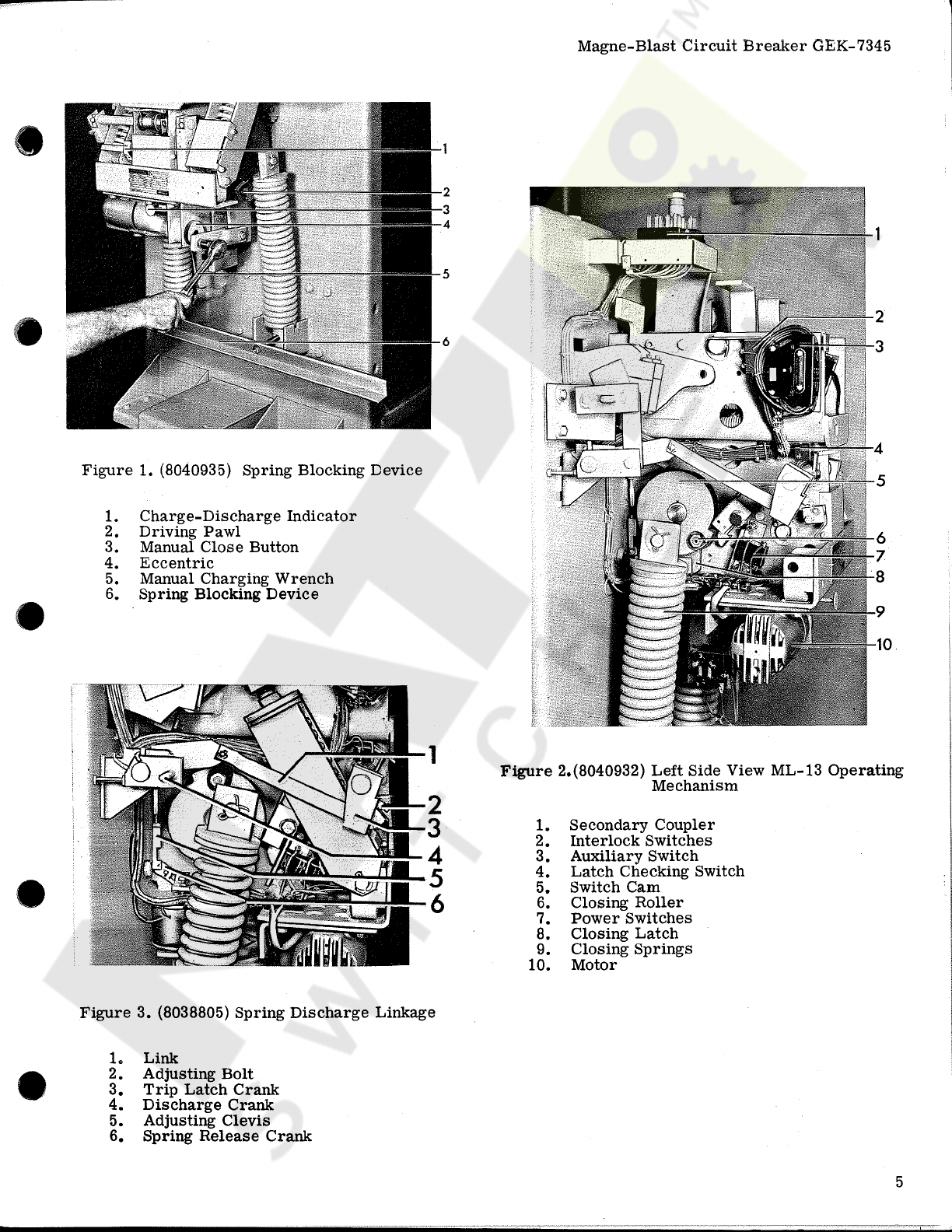
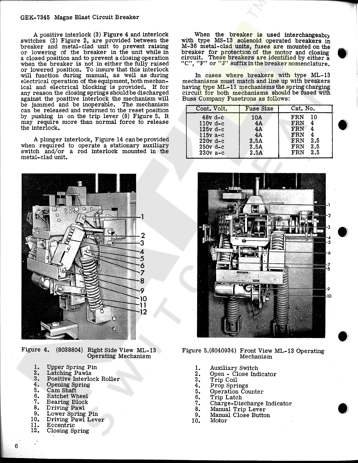
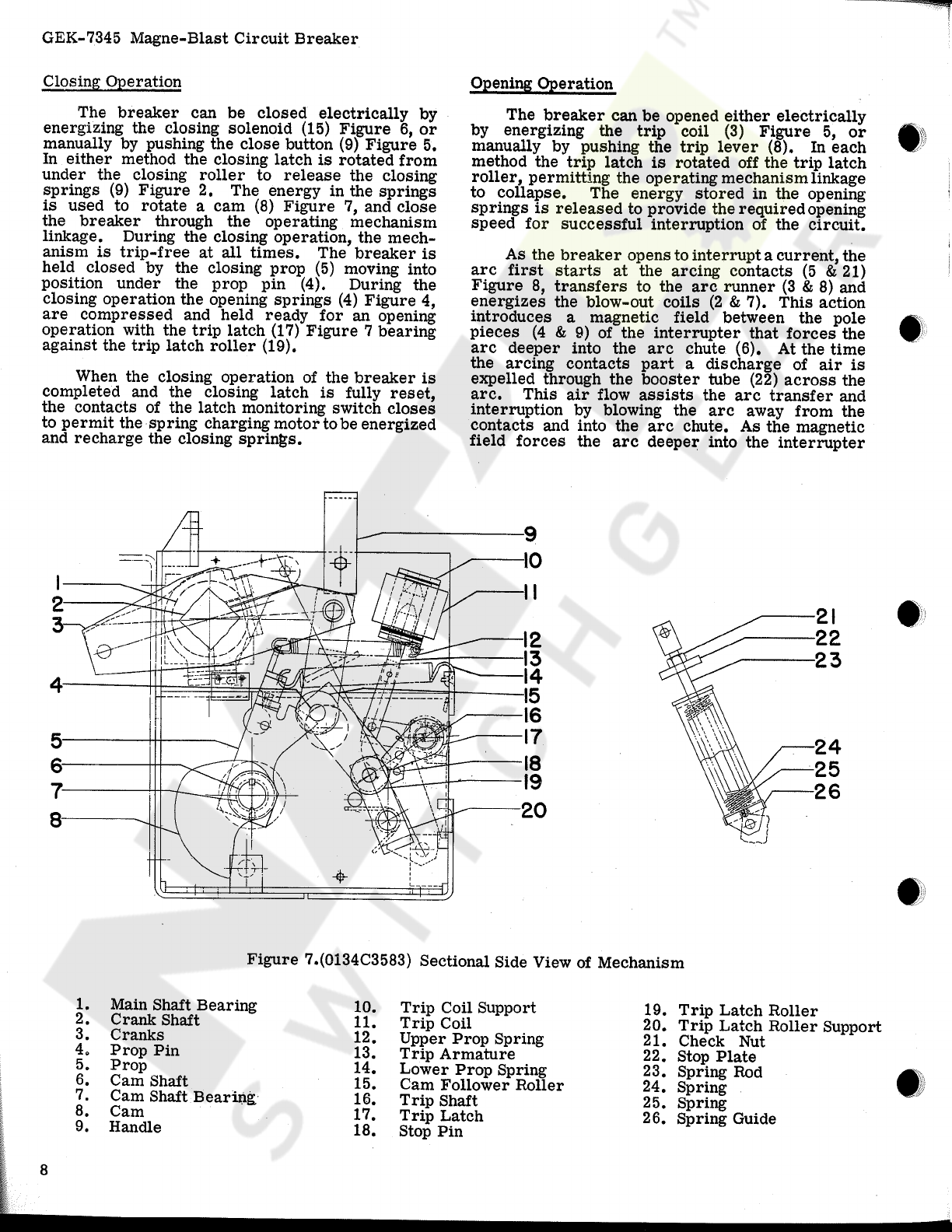
GE GEK-7345 User manual
Other GE Circuit Breaker manuals

GE
GE WavePro 3200 A User manual

GE
GE WavePro LVPCB User guide

GE
GE AK-1-15 Series User manual

GE
GE PowerVac 5kV VL User manual

GE
GE EntelliGuard R7 User manual

GE
GE MicroVersaTrip AK-50 User manual

GE
GE MicroVersa Trip Plus User manual

GE
GE ML-14-0 User manual

GE
GE SF6 User manual

GE
GE POWER BREAK MICRO-VERSATRIP E39ME20 User manual

GE
GE GL 310 F1/4031 P/VR User manual

GE
GE FD 63 User manual

GE
GE MicroVersaTrip Plus User manual

GE
GE AKR-3-50 User manual

GE
GE MicroVersaTrip AKR-75 User manual

GE
GE Power Break II User manual

GE
GE EntelliGuard G User manual

GE
GE Spectra Series AMC6FGB User manual

GE
GE Power Break II User manual

GE
GE GCCC024DR User manual


Popular Circuit Breaker manuals by other brands


Siemens
Siemens Sentron 3VA9157-0PK1 Series operating instructions

hager
hager TS 303 User instruction

ETI
ETI EFI-4B Instructions for mounting

nader
nader NDM3EU-225 operating instructions

TERASAKI
TERASAKI NHP TemBreak PRO P160 Series installation instructions

Gladiator
Gladiator GCB150 Installation instruction