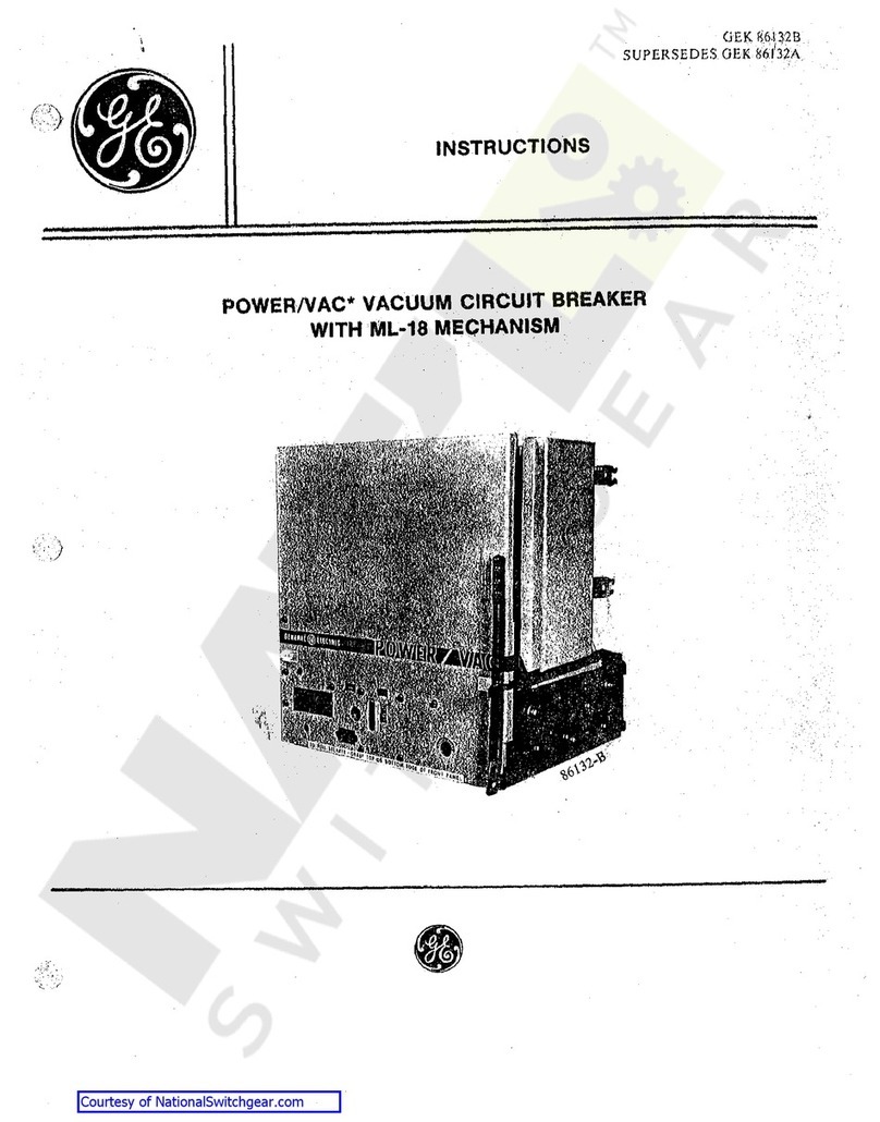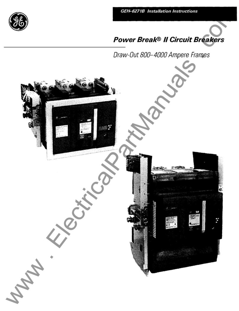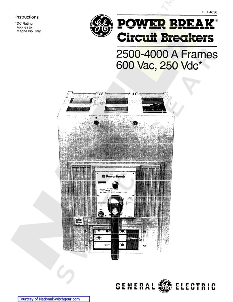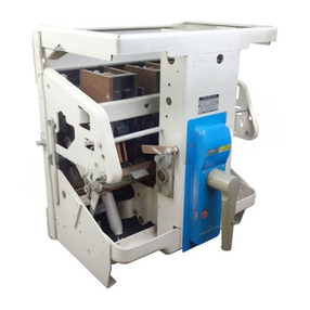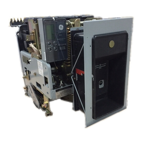
Power
Circuit
Breakers
CONTENTS
Description
P~ge
".........,.
•
.......,,,..,_,_~-··----·...,.-~,
..
~~
........
~··---~·~~~=""-"'•r.•·•"'"~~,.-""",,_,,_...,._,,,~
-.-..~.,~-~-
..._
~-._
...
,
..
•»k·=•~»
.•,,,
...
·'
--~="~·=··~-
SE
CT~Ot~
·1
~
....
,
Reciii~h1~~1g~
and Storage
,, ,,
..
,.
.
..
. .
.:J
SECTION 2
~
lnstalhi·Uon
................
3
Location . . . . . . . . . . . . . . . . . . . . . . . . . . . . .
........
3
Stationary Breakers (God9
S)
......................
3
Draw Out Breakers (Code
D)
.......................
3
Breaker Insertion
...........................
.4
Breaker Removal
...........................
.4
SECTION 3 -
Operation
.................
5
Electrical Operation
.............................
5
Manual Operation
...............................
6
Connections
...................................
6
Control Connections
.........................
6
SECTION 4 -
Maintenance
..............
8
Inspection
.....................................
8
Separation
of
Front and Back Frame
................
8
Lubrication
....................................
8
Troubleshooting
................................
9
SECTION 5 -
Basic
Breaker
Components
.............
10
Disconnects
..................................
10
Primary Disconnects
........................
1O
Secondary Disconnects
......................
1O
Replacement of Movable Secondary
Disconnects
...........................
10
Arc Quencher
.................................
11
Replacement
..............................
11
BreakerContactStructure
.......................
11
Contact Adjustments
............................
11
Contact Replacement
...........................
12
General Preparation
........................
12
Removal
of
Movable Contacts
.................
12
Removal of StationaryContacts
...............
12
Replacement of StationaryContacts
............
12
Replacement
of
Movable Contacts
.............
14
Contact Springs
............................
14
Mechanism
...................................
14
Adjustment
................................
15
Latch Adjustment
...........................
16
Mechanism Replacement
....................
16
Removal of Front Escutcheon of
Manual Breakers
.......................
16
Auxiliary Switch
................................
16
Replacement
..............................
17
2 ©
1984
General Electric Company
.i?!!S~~-iJ~ti?!!_.
___
~--,,·--···-·
--
..
-~·
--
..
···-----·-~~ge
SECT;ON 6
~-
Electrica.1
Replacernent
Ccm·troi
Components
..
1?
Glo5ing Solenoid
...............................
11
Coil Fl:aplacement . . . . . . . . . . . . . .
..
. . . .i 7
"K"Reiay
....................................
17
"E"
Relay
....................................
i 7
Reµiacernerri
..............................
·1
7
Cut-off Switch
.................................
17
Replacement -
..............................
18
Closing Switch
................................
18
Replacement
..............................
18
ShuntTrip Device
..............................
19
Replacement
..............................
20
Adjustment
................................
20
SECTION 7 -
Protective
Devices
.....
21
Undervoltage Device
...........................
21
Adjustment
................................
21
Static Time-Delay Undervoltage
...................
22
Electric Lockout Device
.........................
22
Bell Alarm Switch and/or Lockout Attachments
.......
23
Operation
.................................
23
Open Fuse Lockout Device (OFLO)
................
24
Operation
.................................
24
Adjustments
...............................
24
Replacement
..............................
24
Draw
Out
Interlocks
............................
25
SECTION 8 - MicroVersaTrip®
Trip
Device
...............
26
Programmer Unit
..............................
26
Fault Trip Indicators
.............................
27
Remote Fault Indication
.........................
27
MicroVersaTrip Installation
.......................
28
Current Sensors
...............................
28
Replacement
..............................
28
Flux Shift Trip Device
...........................
28
Troubleshooting
...............................
29
Resistance Values
..........................
29
False Tripping -Breakers Equipped with
Ground Fault
...........................
30
SECTION 9 -
Electrical
Characteristics
..........
35
SECTION 10-
Renewal
Parts
.........
38
JI·
I
i
!
NOTE: Before installing
or
operating these circuit
breakers, carefullyread Sections
1,
2,
and
3.
SECT~ON
1 -
Receh1ing~
Handling~
and
Storage
Upon
H:-Geipt
uf
a circuit brei:iker, immediatelyexamine for
any
dwnage
01·
loss susiained
in
shipment. Hinjury, loss, or
rough handling is evident,
rne
n damage claim at once with the
transportation company and notity tho nearest General Electric
Sales Office.
Unpack
the circuit breaker as soon as possible after it has
been received. Exercise care in unpacking to avoid
damage
to
the breaker parts. Be sure that no loose
pa~t_s
are missing
or
left
SECTION
2 -
Installation
Location
In choosing a location forthe installation
of
these breakers
there are two factors to be considered. The first isthe location's
environmental impact on the breaker. Betterperformance and
longer life can be expected if the area is clean, dry, dust-free,
and well ventilated.
The
second is convenience for operation
and maintenance. The breaker should be easily accessible to
the operator and there should besufficient space available for
maintenance work.
Stationary
Breaker$
(Code
S)
These breakers are designed for mounting in a switchboard
or
enclosure designed and constructed byothers. Mounting
consists
of
bolting the breaker frame to a supporting structure
within the switchboard
or
enclosure, connecting the power
buses
or
cables, and making any necessarycontrol
connections. The front cover of the breaker enclosure may be a
hinged dooror a plate bolted to the panel, including a cutout
opening through which
the
front escutcheon
of
the breaker can
protrude.
The surface on which the breaker is mounted must be flat to
avoid internal distortion
of
the breaker. The supporting structure
must be rigid enough to avoid any possibility
of
the breaker
studs supporting the weight
of
the breaker. Minimum cutout
dimensions as given by the appropriate outline drawing must be
maintained to provide adequate electrical clearance.
Connecting bus and cables
must
be rigidly supported to prevent
unduestress on the breaker terminals.
ir1
!he
µ<:1c~.i:l.ying
material. Biow
cut
any
din
or
ioosa
particies
of
packaging materiai remaininq on or in
Hm
breakec
ii
Hie ci1cui!
breaker
is nut to be placed in service at once,
store it in a clean,
dry
location in an upright position.
Support
it
to prevent bendiny of the studs or damage to any
of
the breaker
parts. Do not coverthe-breaker with packing
or
other material
which absorbs moisture that maycause corrosion
of
breaker
parts. A covering of kraft or othernon-absorbent paper will
prevent dustfrom settling on the breaker.
The outline drawings in Table 1 provide basic dimensional
information for designing the panel or enclosure mounting.
Table 1 -
Outline
Drawings
Breaker Type
AKR-30S Draw Out
AKRU-30S Draw Out
AKR-30S Stationary
Outline
Dwg
No.
139C5317
139C5318
139C5319
Draw
Out
Breakers
-
Code
D
AKD-8
Switchgear
and
Substructure
The
draw
out breaker is supported bytwo protruding pins
on each side of its frame; these pins engage slots in telescoping
slide rails (tracks) mounted to each sidewall
of
the switchgear.
All
draw
out breakers are equipped with a deep escutcheon
with side labels showing these discrete positions:
CONNECTED-This is the breaker's
"in-service"
position.
It is fully inserted in its compartment; the primaryand secondary
disconnectcontacts are fully engaged. The breaker
must
be
tripped before it can be racked intoor out of this position.
TEST -In this position the primary contacts are
disconnected but secondary contacts remain engaged. This
allows complete breaker operation without energizing
the
primary circuit.
3
Courtesy of NationalSwitchgear.com
