GE Mini COM Express 10 Quick user guide

GE
Intelligent Platforms
GFK-2896
Mini COM Express Type 10 Module
mCOM10-L1500
Hardware Reference Manual
For public disclosure

These instructions do not purport to cover all details or variations in equipment, nor to provide for every possible
contingency to be met during installation, operation, and maintenance. The information is supplied for informational
purposes only, and GE makes no warranty as to the accuracy of the information included herein. Changes, modifications,
and/or improvements to equipment and specifications are made periodically and these changes may or may not be reflected
herein. It is understood that GE may make changes, modifications, or improvements to the equipment referenced herein or to
the document itself at any time. This document is intended for trained personnel familiar with the GE products referenced
herein.
This document is approved for public disclosure.
GE may have patents or pending patent applications covering subject matter in this document. The furnishing of this
document does not provide any license whatsoever to any of these patents.
GE provides the following document and the information included therein as is and without warranty of any kind, expressed
or implied, including but not limited to any implied statutory warranty of merchantability or fitness for particular purpose.
For further assistance or technical information, contact the nearest GE Sales or Service Office, or an authorized GE Sales
Representative.
Issued: Aug 2014
Copyright © 2014 General Electric Company, All rights reserved.
___________________________________
* Indicates a trademark of General Electric Company and/or its subsidiaries.
All other trademarks are the property of their respective owners.
Refer to the section, Contact Information for support on this product.
Please send documentation comments or suggestions to controls.doc@ge.com
For public disclosure

Acronyms and Abbreviations
ACPI Advanced Configuration and Power Interface
APIC Advanced Programmable Interrupt Controller
ATA AT Attachment
BIOS Basic Input/Output System
BIT Built-In Test
COM Computer on Module
CPU Central Processing Unit
DDR3 SDRAM Third-Generation Double Data Rate Synchronous Dynamic RAM
DMA Direct Memory Access
DIMM Dual In-line Memory Module
DP DisplayPort
DVI Digital Visual Interface
ECC Error Correcting Code
eDP Embedded DisplayPort
EEPROM Electrically-Erasable Programmable Read-Only Memory
EFI Extensible Firmware Interface
EHCI Enhanced Host Controller Interface
FPGA Field-Programmable Gate Array
FRU Field Replaceable Unit
GPIO General-Purpose Input/Output
GPU Graphics Processing Unit
HDMI High-Definition Multimedia Interface
I2C Inter-Integrated Circuit
IEEE Institute of Electrical and Electronic Engineers
JTAG Joint Test Access Group
LAN Local Area Network
LPC Low Pin-Count
LSB Least-Significant Byte
LVDS Low-Voltage Differential Signaling
MAC Media Access Control
MDI Media-Dependent Interface
MSB Most-Significant Byte
MSI Message-Signaled Interrupt
NMI Non-Maskable Interrupt
OS Operating System
PCI Peripheral Component Interconnect
PCIe PCI Express
PHY Physical
PIC Programmable Interrupt Controller
PICMG PCI Industrial Computer Manufacturers Group
PXE Preboot Execution Environment
RoHS Reduction of Hazardous Substances
RTC Real-Time Clock
SATA Serial ATA
SCI System Control Interrupt
Hardware Reference Manual GFK-2896 3
For public disclosure

SIMD Single Instruction, Multiple Data
SKU Stock-keeping unit
SMBus System Management Bus
SMI System Management Interrupt
SPD Serial Presence Detect
SPI Serial Peripheral Interconnect
SR-IOV Single Root I/O Virtualization
TAP Test Access Port
TDP Thermal Design Power
TPM Trusted Platform Module
UART Universal Asynchronous Receiver/Transmitter
UDIMM Unbuffered DIMM
UEFI Unified EFI
UHCI Universal Host Controller Interface
USB Universal Serial Bus
VMDq Virtual Machine Device Queues
WDT WatchDog Timer
4 GFK-2896 Mini COM Express Type 10 Module mCOM10-L1500
For public disclosure

Safety Symbol Legend
Warning
Indicates a procedure, condition, or statement that, if not
strictly observed, could result in personal injury or death.
Caution
Indicates a procedure, condition, or statement that, if not
strictly observed, could result in damage to or destruction of
equipment.
Attention
Indicates a procedure, condition, or statement that should be
strictly followed to improve these applications.
For public disclosure

Support, Service, and Warranty
For support on the web and
product information, visit
our website at http://www.
ge-ip.com/.
This section provides information about our product warranty terms and details about what
action to take if you experience a problem with the product.
Warranty
The manufacturer grants the original purchaser of GE Intelligent Platforms products a warranty
of 24 months from the date of delivery. For details regarding this warranty, refer to the Terms
and Conditions of the initial sale.
Support
The GE Intelligent Platforms’ product support program features two regional support
headquarters and regional customer centers for support, service, RMA returns, and other
functions.
World-wide headquarters of GE Intelligent Platforms, Inc.
GE Intelligent Platforms Inc.
2500 Austin Drive
Charlottesville, VA 22911 U.S.A.
Regional Areas
WW world-wide
EU Europe, Russia, Near East, India, Africa
US Americas and Pacific Rim (Japan, Korea, China, Philippines, AUS, NZ)
Technical Support
Free technical support is available by phone or email. Telephone support is available at main
locations or at the regional center where the product was purchased.
Support Contact Information
Germany US
Monday through Thursday 8:00 – 17:00 (CET)
Friday 8:00 – 16:00 (CET)
Monday through Friday 8:30 AM – 5:30 PM (Eastern Time)
Phone: +49-821-5034-170
Fax: +49-821-5034-119
Phone: +1-800-322-3616
6 GFK-2896 Mini COM Express Type 10 Module mCOM10-L1500
For public disclosure

Contents
1 Introduction ..................................................................................................................................... 11
1.1 Features............................................................................................................................................... 12
2 Unpacking and Inspection ........................................................................................................... 15
2.1 Electrostatic Discharge ........................................................................................................................... 15
2.2 Package Contents................................................................................................................................... 16
2.3 Unpacking and Inspecting ....................................................................................................................... 16
2.4 Handling.............................................................................................................................................. 17
3 Installation and Startup................................................................................................................. 19
3.1 Required Materials................................................................................................................................. 19
3.1.1 Carrier Board and Power Supply........................................................................................................ 19
3.1.2 Keyboard and Mouse....................................................................................................................... 19
3.1.3 Video Monitor................................................................................................................................ 19
3.2 General Installation Guidelines................................................................................................................. 20
3.3 Installation Procedures............................................................................................................................ 21
3.3.1 Install the mCOM10-L1500 onto the Carrier Board ............................................................................... 21
3.3.2 Install the Combined Unit................................................................................................................. 22
3.4 Initial Startup........................................................................................................................................ 22
3.4.1 UEFI Firmware Setup...................................................................................................................... 22
4 System Architecture ...................................................................................................................... 23
4.1 G-Series SoC Processor .......................................................................................................................... 23
4.1.1 Memory ........................................................................................................................................ 24
4.1.2 Digital Display Interface .................................................................................................................. 24
4.1.3 PCI Express ................................................................................................................................... 24
4.1.4 BIOS/UEFI Firmware...................................................................................................................... 25
4.1.5 Serial ATA..................................................................................................................................... 25
4.1.6 USB ............................................................................................................................................. 25
4.1.7 Secure Digital or General-purpose I/O................................................................................................. 25
4.1.8 Audio ........................................................................................................................................... 25
4.1.9 Clocks .......................................................................................................................................... 26
4.1.10 Real-Time Clock and CMOS RAM .................................................................................................... 26
4.1.11 LPC Bus ....................................................................................................................................... 26
4.1.12 SMBus.......................................................................................................................................... 26
4.2 Gigabit Ethernet Interface ....................................................................................................................... 27
4.3 FPGA.................................................................................................................................................. 28
4.3.1 Watchdog Timer ............................................................................................................................. 28
4.3.2 I2C Bus ......................................................................................................................................... 28
4.3.3 Serial Ports .................................................................................................................................... 28
4.4 Power Distribution................................................................................................................................. 29
4.4.1 Supervision and Reset...................................................................................................................... 29
4.4.2 Power Reset Sequence ..................................................................................................................... 29
4.4.3 Thermal Management ...................................................................................................................... 29
4.5 Test and Debug ..................................................................................................................................... 30
4.6 Fan Monitor.......................................................................................................................................... 30
GFK-2896 Hardware Reference Manual 7
For public disclosure

4.7 LED Status Indicators............................................................................................................................. 30
5 Configuration................................................................................................................................... 31
5.1 Hardware ............................................................................................................................................. 31
5.1.1 COM Express Type 10 Module Connectors.......................................................................................... 31
5.1.2 JTAG Connector............................................................................................................................. 40
5.1.3 PCIe Ports ..................................................................................................................................... 41
5.2 Software .............................................................................................................................................. 42
5.2.1 Memory and I/O Address Mapping..................................................................................................... 42
5.2.2 SMBus Slave Devices...................................................................................................................... 42
5.2.3 I2C Slave Devices ........................................................................................................................... 42
5.2.4 External Interrupts........................................................................................................................... 42
5.2.5 GPIO............................................................................................................................................ 43
6 FPGA Registers .............................................................................................................................. 45
6.1 Configuration Access Port....................................................................................................................... 45
6.1.1 Index Port...................................................................................................................................... 45
6.1.2 Data Port....................................................................................................................................... 45
6.2 General Configuration Registers............................................................................................................... 46
6.2.1 Logical Device Number ................................................................................................................... 46
6.2.2 Device ID...................................................................................................................................... 46
6.2.3 Version ......................................................................................................................................... 46
6.2.4 Revision........................................................................................................................................ 47
6.2.5 Build Information ........................................................................................................................... 47
6.3 UART Configuration Registers................................................................................................................. 48
6.3.1 UART Control................................................................................................................................ 48
6.3.2 UART Base Address........................................................................................................................ 48
6.3.3 UART Interrupt Request................................................................................................................... 49
6.3.4 UART Mode .................................................................................................................................. 50
6.4 Supervision Configuration Registers.......................................................................................................... 51
6.4.1 Supervision Control......................................................................................................................... 51
6.4.2 Supervision Base Address................................................................................................................. 51
6.5 I2C Controller Configuration Registers....................................................................................................... 52
6.5.1 I2C Control .................................................................................................................................... 52
6.5.2 I2C Base Address ............................................................................................................................ 52
6.5.3 I2C IRQ......................................................................................................................................... 53
6.6 Watchdog Timer Configuration Registers ................................................................................................... 54
6.6.1 Watchdog Timer Control .................................................................................................................. 54
6.6.2 Watchdog Timer Base Address .......................................................................................................... 54
6.6.3 Watchdog Timer IRQ....................................................................................................................... 55
6.6.4 Watchdog Timer Options.................................................................................................................. 55
6.7 UART Run-Time Registers...................................................................................................................... 56
6.7.1 Receive Buffer ............................................................................................................................... 56
6.7.2 Transmit Buffer .............................................................................................................................. 56
6.7.3 Interrupt Enable.............................................................................................................................. 57
6.7.4 Interrupt Identification ..................................................................................................................... 58
6.7.5 FIFO Control ................................................................................................................................. 59
6.7.6 Line Control................................................................................................................................... 60
8 GFK-2896 Mini COM Express Type 10 Module mCOM10-L1500
For public disclosure
6.7.7 Modem Control .............................................................................................................................. 61
6.7.8 Line Status..................................................................................................................................... 62
6.7.9 Modem Status ................................................................................................................................ 63
6.7.10 Scratchpad..................................................................................................................................... 64
6.7.11 Divisor Latch ................................................................................................................................. 64
6.8 Board Supervision Run-Time Registers...................................................................................................... 65
6.8.1 Reset Cause ................................................................................................................................... 65
6.8.2 Last Reset...................................................................................................................................... 66
6.9 I2C Controller Run-Time Registers............................................................................................................ 67
6.9.1 Clock Prescale................................................................................................................................ 67
6.9.2 Control ......................................................................................................................................... 68
6.9.3 Transmit........................................................................................................................................ 68
6.9.4 Receive......................................................................................................................................... 68
6.9.5 Command...................................................................................................................................... 69
6.9.6 Status ........................................................................................................................................... 70
6.9.7 Watchdog Timer Run-Time Registers.................................................................................................. 71
7 Specifications.................................................................................................................................. 73
Glossary of Terms ................................................................................................................................ 75
Index......................................................................................................................................................... 77
GFK-2896 Hardware Reference Manual 9
For public disclosure

Notes
10 GFK-2896 Mini COM Express Type 10 Module mCOM10-L1500
For public disclosure

1 Introduction
The mCOM10-L1500 is a miniature Computer-on-Module (mCOM) Type 10
single-board computer approximately the size of a credit card, based on an AMD
G-Series System-on-chip (SoC). It contains one channel of DDR3L 72-bit ECC memory
and all components necessary for the bootable host computer packaged as a super
component. The mCOM10-L1500 module is combined with a carrier board required to
provide power, and support I/O and startup. The mCOM10-L1500 provides a Gigabit
Ethernet interface, four lanes of PCI Express (PCIe), two Serial ATA (SATA) ports, eight
USB 2.0 host interfaces (two of which support USB 3.0), low-voltage differential
signaling (LVDS) flat-panel or embedded DisplayPort plus a Digital Display Interface
(DDI), LPC, SPI, SMBus, I2C, secure digital or general-purpose I/O, and high-definition
audio ports to the module connector.
Refer to PICMG COM.0 R2.1
COM Express Module Base
Specification, located at
www.picmg.org.
This document describes the mCOM10-L1500 based on the PICMG COM Express
Module Base Specification. The module can operate in convection or conduction-cooled
environments, and uses a wide input-range main power rail (4.75 to 20 V), 5 V Standby,
and 3 V Real-Time Clock (RTC) battery power.
mCOM10-L1500
Introduction GFK-2896 Hardware Reference Manual 11
For public disclosure

1.1 Features
The mCOM10-L1500 provides the following core hardware and firmware features:
• AMD G-Series SoC, including:
− Two or four CPU cores
− GPU core
− Northbridge
− DDR3 memory controller
− Integrated display output
− I/O controller
− Dual-core 9W TDP and quad-core 15W TDP SKUs available
• Single-channel 72-bit DDR3L SDRAM with ECC support: 2 GB, 4 GB, and 8 GB
options
• Gigabit Ethernet interface
• Four PCIe lanes, configurable as either 4×1 or 1×4
• Eight MB SPI Flash for UEFI/BIOS firmware
• Two SATA ports
• Eight USB 2.0 host interfaces, two of which also support USB 3.0 SuperSpeed
• Two simultaneous display outputs: LVDS/eDP (configurable), and DDI
• LPC Bus
• One internal plus one external SPI bus
• SMBus
• I2C bus
• SDIO or GPIO (configurable)
• High-definition Audio
• Two 16550-compatible serial ports
• Express Card support
• Power and system management
• Thermal protection
• 4.75 – 20 V primary power, 5 V Standby, and 3 V RTC power supply input
12 GFK-2896 Mini COM Express Type 10 Module mCOM10-L1500
For public disclosure
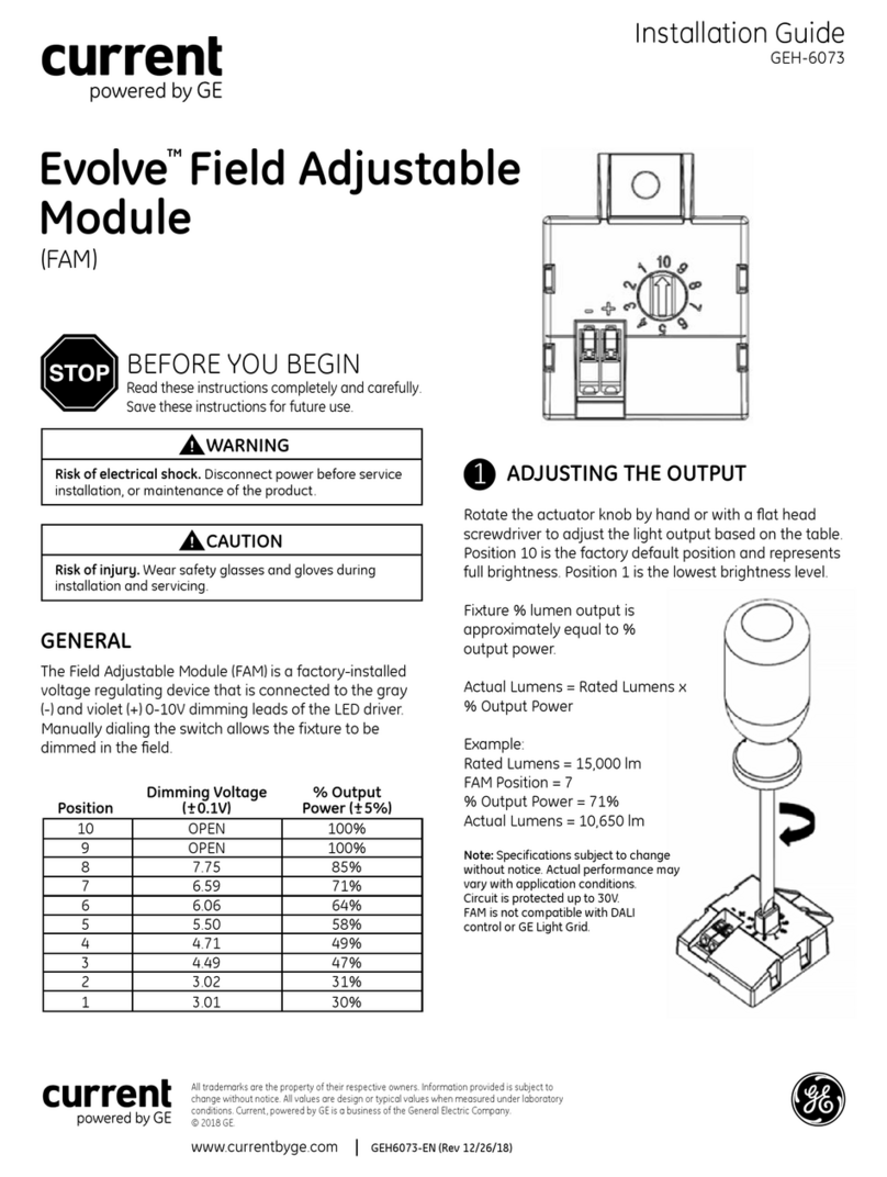
G-Series SoC
CPU Core
L1Cache
CPU Core
L1Cache
CPU Core
L1Cache
CPU Core
L1Cache
L2Cache
NorthBridge
GPU
SouthBridge
LVDS/eDP
DDI0
VGA
I210
PCIe
PCIe[0:3]
GbE0
DDR3L
2/4/8GB
ECC
2x SATA
8x USB
2x USB_SS
HDA
GPIO/SD
Flash
SMBus
LPC
FPGA
UART
I2C
WDog
UART
Supv Ser0
Ser1
I2C
WDT
SPD
Debug
SPI
EeeP
SMBus
User
mCOM10-L1500 Functional Block Diagram
Introduction GFK-2896 Hardware Reference Manual 13
For public disclosure

Notes
14 GFK-2896 Mini COM Express Type 10 Module mCOM10-L1500
For public disclosure
2 Unpacking and Inspection
This chapter describes unpacking, initial inspection, and required preparation
considerations prior to using the mCOM10-L1500. Follow the procedures provided in this
chapter to verify proper operation after shipping and prior to system integration.
2.1 Electrostatic Discharge
Electrostatic Discharge (ESD), the discharge of static electricity, is a major cause of
electronic component failure. The module has been packed in a static-safe bag to protect
the board from ESD. Before removing the module or any other electronic product from its
static-safe bag, be prepared to handle it in a static-safe environment.
Warning
Static-sensitive devices; handle only at static safe work
stations.
Caution
This is an FCC Class A product for use in an industrial
environment. In a home or residential environment, this
product may cause radio interference in which case the
user may be required to take adequate measures.
Caution
Drain static electricity before you install or remove any
parts. Installing or removing modules without observing
this precaution could result in damage to this and/or
other modules in your system.
Wear a properly-functioning anti-static strap and make sure you are fully grounded. Any
surface upon which you place the unprotected module should be static-safe, which is
usually facilitated by the use of anti-static mats. From the time the board is removed from
the anti-static bag until it is in the card carrier and functioning properly, extreme care
should be taken to avoid zapping the board with ESD. Be aware that you could zap the
board without knowing it; a small discharge, imperceptible to the eye and touch, can often
be enough to damage electronic components. Extra caution should be taken in cold and
dry weather when electrostatics easily builds up.
Only after ensuring that both you and the surrounding area are protected from ESD,
carefully remove the board or module from the shipping carton by grasping the module
on its edges. Place the board, in its anti-static bag, flat down on a suitable surface. You
may then remove the board from the anti-static bag by tearing the ESD warning labels.
Unpacking and Inspection GFK-2896 Hardware Reference Manual 15
For public disclosure

2.2 Package Contents
Verify that the delivered package contains one mCOM10-L1500 module.
2.3 Unpacking and Inspecting
Warning
Before installing or removing any board, ensure that
the system power and external supplies have been
turned off.
Warning
After unpacking the module, inspect it for visible
damage that could have occurred during shipping or
unpacking. If damage is observed (usually in the form
of bent component leads or loose socketed components),
contact GE Intelligent Platforms for additional
instructions. Depending on the severity of the damage,
it may be necessary to return the product to the factory
for repair.
DO NOT apply power to the board if it has visible
damage. Doing so may cause further, possibly
irreparable damage, as well as introduce a fire or shock
hazard.
Attention
Retain all packing material in case of future need.
Before unpacking the board or module, or fitting the device into your system, read the
manual carefully. Also adhere to the following guidelines:
• Observe all precautions for electrostatic sensitive modules
• If the product contains batteries, do not place the board on conductive surfaces,
anti-static plastic, or sponge, which can cause shocks and lead to battery or board
trace damage. Do not exceed the specified operational temperatures. Batteries and
storage devices might also have temperature restrictions.
• Keep all original packaging material for future storage or warranty shipments of the
board.
Although the module is carefully packaged to protect it against the rigors of shipping, it is
still possible that shipping damages may occur. Careful inspection of the shipping carton
should reveal some information about how the package was handled by the shipping
service. If evidence of damage or rough handling is found, notify the shipping service and
GE Intelligent Platforms as soon as possible.
16 GFK-2896 Mini COM Express Type 10 Module mCOM10-L1500
For public disclosure
2.4 Handling
Proper handling of the board or module is critical to ensure proper operation and
long-term reliability. When unpacking and handling the board, be sure to hold the board
as displayed in the following figure.
Board Handling
Unpacking and Inspection GFK-2896 Hardware Reference Manual 17
For public disclosure

Notes
18 GFK-2896 Mini COM Express Type 10 Module mCOM10-L1500
For public disclosure

3 Installation and Startup
This chapter describes the installation of the mCOM10-L1500 module on a carrier board
and initial startup operations.
3.1 Required Materials
The following items are required to start the board in a standard configuration:
•Carrier board and power supply
•Keyboard and mouse
•Video monitor
3.1.1 Carrier Board and Power Supply
A carrier routes the I/O signals
of the mCOM10-L1500 to the
connectors.
Refer to chapter,
Specifications.
You will need a carrier board wired with either an integrated or external regulated power
supply capable of providing stable low noise primary and standby sources. Verify that the
supply meets the voltage and total power requirements of the mCOM10-L1500.
Warning
Verify that the power supply is turned OFF while
plugging or unplugging the board onto or from a
carrier card, respectively.
3.1.2 Keyboard and Mouse
The keyboard is attached to the
carrier board.
A compatible keyboard for initial system operation on the carrier board is required.
Depending on your application, this may be a standard keyboard, or one that uses
membrane switches for harsh environments.
3.1.3 Video Monitor
Any video monitor with an appropriate connection to a Digital Display Interface (DDI)
can be used initially for display output. Compatible interfaces are DisplayPort, DVI, and
HDMI. Access to the video signal is provided through the carrier board.
Installation and Startup GFK-2896 Hardware Reference Manual 19
For public disclosure

3.2 General Installation Guidelines
Adhere to the following guidelines during installation:
• Observe all safety procedures to avoid damaging the system and protect operators
and users.
• Before installing or removing any board, verify that the system power and external
supplies have been turned off.
• Verify that the jumpers on the carrier board are correctly configured for your
application.
• Mount the board on the carrier board very carefully. Refer to the procedure, To install
the mCOM10-L1500 onto the carrier board.
• Do not restore power until all modules are fitted correctly and all connections have
been made properly.
20 GFK-2896 Mini COM Express Type 10 Module mCOM10-L1500
For public disclosure
This manual suits for next models
1
Table of contents
Other GE Control Unit manuals

GE
GE Evolution Series E9000 User manual

GE
GE CR194 User manual

GE
GE MiCOM P40 Agile User manual

GE
GE VersaMax IC200ALG630 User manual

GE
GE NetworX Series Installation manual

GE
GE IC693CBL300 User manual

GE
GE IC3645SR4W606N6 Owner's manual

GE
GE C-400 Series User manual

GE
GE MiCOM P40 Agile User manual

GE
GE IC695CMM002CA-EJ User manual

GE
GE b30 User manual

GE
GE IC3645SR4T405E1 User manual

GE
GE NX-1710E - Single Door Control Module Installation and operation manual

GE
GE PACSystems RX3i IC695ETM001-JW User manual

GE
GE EntelliGuard TU User manual

GE
GE L60 User manual

GE
GE Intellix BMT 330 User manual

GE
GE 21861 User manual

GE
GE Spectra Series User manual

GE
GE CAM-14 User manual