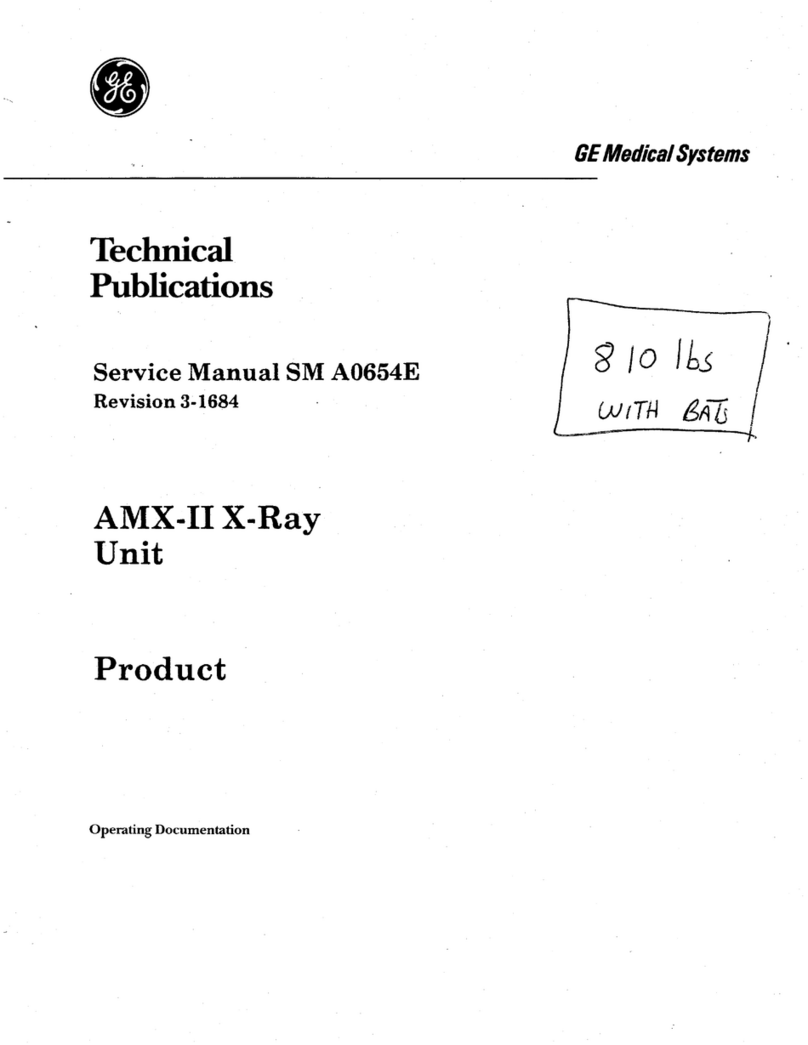
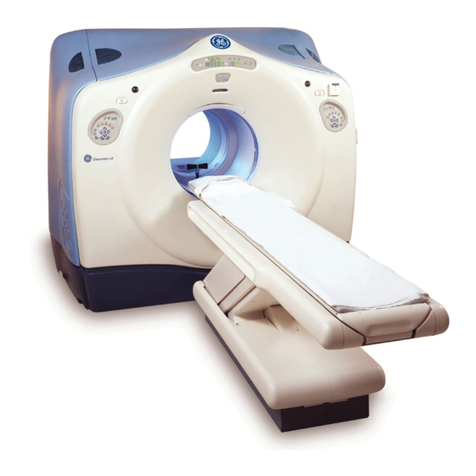
GE Advantium CT9800 User manual

Technical
Publications
Direction 46-018000
Revision24
GE Medical Systems
General Service Manual
CT-9800 Quick System
Copyright 1999by General Electric Company
Operating Documentation


Rev. 23
GENERAL ELECTRIC MEDICAL SYSTEMS
Direction 46–018000
CT 9800 QUICK SYSTEM
A
THISSERVICE MANUAL IS
AVAILABLE IN ENGLISH ONLY.
WARNING
IFA CUSTOMER’SSERVICE PROVIDER REQUIRES A LANGUAGE
OTHER THAN ENGLISH, IT IS THE CUSTOMER’SRESPONSIBILITY
TO PROVIDE TRANSLATION SERVICES.
DO NOT ATTEMPTTOSERVICE THE EQUIPMENT UNLESS THIS
SERVICE MANUAL HAS BEEN CONSULTED AND IS UNDERSTOOD.
FAILURETO HEED THIS WARNING MAY RESULT IN INJURY TO
THESERVICEPROVIDER,OPERATOR OR PATIENTFROMELECTRIC
SHOCK, MECHANICAL OR OTHER HAZARDS.
CE MANUEL DE
MAINTENANCEN’EST
DISPONIBLE QU’EN ANGLAIS.
AVERTISSEMENT
SILE TECHNICIEN DU CLIENT A BESOIN DE CE MANUEL DANS
UNE AUTRE LANGUE QUE L’ANGLAIS, C’EST AU CLIENT QU’IL
INCOMBE DE LE FAIRETRADUIRE.
NEPAS TENTER D’INTERVENTION SUR LES ÉQUIPEMENTS TANT
QUE LE MANUEL SERVICE N’A PAS ÉTÉ CONSULTÉET COMPRIS.
LENON-RESPECT DE CET AVERTISSEMENTPEUTENTRAÎNER
CHEZ LE TECHNICIEN, L’OPÉRATEUR OU LE PATIENTDES
BLESSURESDUES À DES DANGERS ÉLECTRIQUES, MÉCANIQUES
OUAUTRES.
DIESESKUNDENDIENST–HANDBUCH
EXISTIERT NUR IN ENGLISCHER
SPRACHE.
WARNUNG
FALLSEIN FREMDER KUNDENDIENST EINE ANDERE SPRACHE
BENÖTIGT, IST ES AUFGABE DES KUNDEN FÜR EINE
ENTSPRECHENDEÜBERSETZUNGZUSORGEN.
VERSUCHENSIE NICHT, DAS GERÄT ZU REPARIEREN,BEVOR
DIESES KUNDENDIENST–HANDBUCH NICHT ZU RATEGEZOGEN
UND VERSTANDENWURDE.
WIRDDIESE WARNUNG NICHT BEACHTET, SO KANN ES ZU
VERLETZUNGENDESKUNDENDIENSTTECHNIKERS,DES
BEDIENERS ODER DES PATIENTENDURCHELEKTRISCHE
SCHLÄGE,MECHANISCHE ODER SONSTIGE GEFAHRENKOMMEN.
ESTE MANUAL DE SERVICIO
SÓLO EXISTE EN INGLÉS.
AVISO
SIALGÚN PROVEEDOR DE SERVICIOS AJENO A GEMS SOLICITA
UN IDIOMA QUE NO SEA EL INGLÉS, ES RESPONSABILIDAD DEL
CLIENTE OFRECER UN SERVICIO DE TRADUCCIÓN.
NO SE DEBERÁ DAR SERVICIO TÉCNICO AL EQUIPO, SIN HABER
CONSULTADO Y COMPRENDIDO ESTE MANUAL DE SERVICIO.
LANO OBSERVANCIA DEL PRESENTE AVISO PUEDE DAR LUGAR
A QUE EL PROVEEDOR DE SERVICIOS, EL OPERADOR O EL
PACIENTESUFRAN LESIONES PROVOCADAS POR CAUSAS
ELÉCTRICAS, MECÁNICAS O DE OTRA NATURALEZA.
ESTE MANUAL DE ASSISTÊNCIA
TÉCNICA SÓ SE ENCONTRA
DISPONÍVELEM INGLÊS.
ATENÇÃO
SEQUALQUER OUTRO SERVIÇO DE ASSISTÊNCIA TÉCNICA,
QUE NÃO A GEMS, SOLICITAR ESTES MANUAIS NOUTRO IDIOMA, É
DA RESPONSABILIDADE DO CLIENTE FORNECER OS SERVIÇOS DE
TRADUÇÃO.
NÃO TENTE REPARAR O EQUIPAMENTO SEM TER CONSULTADO
E COMPREENDIDO ESTE MANUAL DE ASSISTÊNCIA TÉCNICA.
O NÃO CUMPRIMENTO DESTE AVISO PODE POR EM PERIGO A
SEGURANÇA DO TÉCNICO, OPERADOR OU PACIENTE DEVIDO A‘
CHOQUESELÉTRICOS, MECÂNICOS OU OUTROS.
IL PRESENTE MANUALE DI
MANUTENZIONEÈ DISPONIBILE
SOLTANTO IN INGLESE.
AVVERTENZA
SEUN ADDETTO ALLA MANUTENZIONE ESTERNO ALLA GEMS
RICHIEDE IL MANUALE IN UNA LINGUA DIVERSA, IL CLIENTE È
TENUTO A PROVVEDERE DIRETTAMENTEALLA TRADUZIONE.
SI PROCEDA ALLA MANUTENZIONE DELL’APPARECCHIATURA
SOLO DOPO AVER CONSULTATO IL PRESENTE MANUALE ED AVERNE
COMPRESO IL CONTENUTO.
NON TENERE CONTO DELLA PRESENTE AVVERTENZA
POTREBBEFAR COMPIERE OPERAZIONI DA CUI DERIVINO LESIONI
ALL’ADDETTO ALLA MANUTENZIONE, ALL’UTILIZZATORE ED AL
PAZIENTE PER FOLGORAZIONE ELETTRICA, PER URTIMECCANICI
OD ALTRIRISCHI.

Rev. 23
GENERAL ELECTRIC MEDICAL SYSTEMS
Direction 46–018000
CT 9800 QUICK SYSTEM
B
IMPORTANT! . . . X-RAY PROTECTION
X-ray equipment if not properly used may cause
injury.Accordingly, the instructions herein contained
should be thoroughly read and understood by
everyone who will use the equipment before you
attempt to place this equipment in operation. The
General Electric Company, Medical Systems Group,
will be glad to assist and cooperate in placing this
equipment in use.
Althoughthis apparatus incorporates a high degree of
protection against x-radiation other than the useful beam,
no practical design of equipment can provide complete
protection. Nor can any practical design compel the
operator to take adequate precautions to prevent the
possibilityof any persons carelessly exposing themselves
or others to radiation.
It is important that everyone having anything to do with
x-radiationbeproperlytrainedandfullyacquaintedwiththe
recommendations of the National Council on Radiation
Protection and Measurements as published in NCRP
Reports available from NCRP Publications, 7910
Woodmont Avenue, Room 1016, Bethesda, Maryland
20814, and of the International Commission on Radiation
Protection, and take adequate steps to protect against
injury.
The equipment is sold with the understanding that the
General Electric Company, Medical Systems Group, its
agents, and representatives have no responsibility for
injuryordamagewhichmayresultfromimproperuseofthe
equipment.
Variousprotective material and devices are available. It is
urgedthat such materials or devices be used.
CERTIFIEDELECTRICAL CONTRACTOR
STATEMENT
All electrical installations that are preliminary to positioning of
theequipment at the siteprepared for theequipment shall be
performed by licensed electrical contractors. In addition,
electrical feeds into the Power Distribution Unit shall be
performed by licensed electrical contractors. Other
connections between pieces of electrical equipment,
calibrations, and testing shall be performed by qualified GE
Medical personnel. The productsinvolved (and the
accompanying electrical installations) are highly sophisti-
cated, and special engineering competence is required.
In performing all electrical work on these products, GE will
use its own specially trained field engineers. All of GE’s
electrical work on these products will comply withthe
requirements of the applicable electrical codes.
The purchaser of GE equipment shall only utilize qualified
personnel (i.e.,GE’sfield engineers, personnel of third-party
service companies withequivalent training, or licensed
electricians) to perform electrical servicing on the equipment.
DAMAGEIN TRANSPORTATION
All packages should be closely examined at time of
delivery.If damage is apparent, havenotation“damage in
shipment”writtenonall copiesofthefreightorexpressbill
before delivery is accepted or “signed for” by a General
Electric representative or a hospital receiving agent.
Whether noted or concealed, damage MUST be reported
tothe carrierimmediately upondiscovery, orinanyevent,
within14 days after receipt, and the contents and
containers held for inspection by the carrier.A
transportation company will not pay a claim for damage if
an inspection is not requested within this 14 day period.
CallTraffic and Transportation, Milwaukee, WI (414)
827–3449/ 8*285–3449 immediately after damage is
found. At this time be ready to supply name of carrier,
deliverydate, consignee name, freight or express bill
number, item damaged and extent of damage.
Complete instructions regarding claim procedure are
found in Section “S” of the Policy & Procedure Bulletins.
OMISSIONS& ERRORS
Customers, please contact your GE Sales or Service
represenatives.GEpersonnel,pleaseusetheGEMSCQA Process to report all omissions, errors, and defects in this
documentation.
Rev. 24
GENERAL ELECTRIC MEDICAL SYSTEMS
Direction 46-018000
CT 9800 QUICK SYSTEM
0-1
CT9800 QUICK SYSTEM CHAPTERS 4-8
REVISION HISTORY
REV DATE REASON FOR CHANGE REV DATE REASON FOR CHANGE
1Feb. 21, 1986 Initial Production Release (SA
Sftw) 12 Sept. 1, 1988 WA Software Release HTD
and HiLight Updates
2June 20, 1986 SB Software Release 1 13 April 1, 1989 WB Software Release
3Dec. 19, 1986 SC Software Release 14 June 1, 1990 WD Software Release
4Feb. 20, 1987 SD Software Release (MV7800
& Optical Disk) 15 July 30, 1990 Introduction of fanless E-DAS
5March 11, 1987 Correct pg. 4-10-7 in SD
Errata. 16 April 19, 1991 WE Software Release,
Updates
6June 12, 1987 New Table/Gantry Alignment.
Also, Laser Light Alignment Tool 17 June 22, 1992 WF Software Release
7June 26, 1987 Optical Disk Introduction 18 March 3, 1993 Q-Cal & Dial Indicator Mtg.
Updates
8Oct. 23, 1987 SE Software Release 19 Dec. 6, 1993 WG Software Release
9Jan. 22, 1988 ACE and 80KV XFMR 20 Dec. 20, 1993 WH Software Release
10 July 8, 1988 E-DAS Introduction 21 Aug. 1, 1995 IB Documentation Clean-Up
11 Aug. 22, 1988 ACE Diag. (BA Rev.) 22
Oct 15, 1998
CQA 975516
23
April 3, 1998
CQA 976244
June 1, 1999
24 WI Software Release &
Y2K Update

GENERAL ELECTRIC MEDICAL SYSTEMS CT 9800 QUICK SYSTEM
REV 24 DIRECTION 46-018000
0-2
List of Effective Pages
PAGE
NUMBER
REVISION
NUMBER
PAGE
NUMBER
REVISION
NUMBER
PAGE
NUMBER
REVISION
NUMBER
Title/Blank 24 4-4 to 4-8 omitted 4-12-25 to 4-12-28 deleted
A to B 23 4-9-1 to 4-9-4 14-12-29 to 4-12-32 20
0-1 to 0-4 24 4-9-5 & 4-9-6 44-13-1 to 4-13-7 19
i 1 4-10-1 to 4-10-4 24 4-13-8 blank
ii blank 4-10-5 16 4-A-1 to 4-A 2 1
i-A-1 to i-A-5 14-10-6 24 6-i 12
i-A-6 blank 4-10-7 & 4-10-8 16 6-ii 13
4-i 12 4-10-9 to 4-10-12 24 6-1-1 3
4-ii 19 4-10-13 16 6-1-2 blank
4-1-1 14-10-14 24 6-2-1 1
4-1-2 34-10-14A/14B 17/blank 6-2-2 blank
4-1-3 19 4-10-15 16 6-3-1 to 6-3-22 1
4-1-4 12 4-10-16 & 4-10-17 24 6-4-1 1
4-1-5 10 4-10-18 19 6-4-2 blank
4-1-5A 10 4-10-19 24 6-5 to 6-8 omitted
4-1-5B blank 4-10-20 20 6-9-0 19
4-1-6 44-10-21 to 4-10-23 19 6-9-0A 20
4-1-7 13 4-10-24 16 6-9-1 to 6-9-3 12
4-1-8 to 4-1-10 44-11-1 20 6-9-4 19
4-2-1 to 4-2-12 14-11-2 to 4-11-4 19 6-9-5 to 6-9-10 12
4-2-13 16 4-12-1 19 6-9-11 16
4-2-14 blank 4-12-2 to 4-12-6 12 6-9-12 to 6-9-16 12
4-3-1 to 4-3-26 94-12-7 14 6-9-17 & 6-9-18 16
4-3-27 24 4-12-8 & 4-12-9 12 6-9-19 12
4-3-28 to 4-3-30 14 4-12-10 to 4-12-12 blank 6-9-20 16
4-3-31 & 4-3-32 24 4-12-13 12 6-9-21 to 6-9-28 12
4-3-33 14 4-12-14 16-9A-0 19
4-3-34 to 4-3-39 24 4-12-15 to 4-12-17 12 6-9A-0A 20
4-3-40 to 4-3-44 14 4-12-18 blank 6-9A-1 & 6-9A-2 12
4-3-45 24 4-12-19 20 6-9A-3 19
4-3-46 14 4-12-20 blank 6-9A-4 & 6-9A-5 12
4-3-47 to 4-3-49 24 4-12-21 20 6-9A-6 13
4-3-49A & 4-3-49B 24 4-12-22 blank 6-9A-7 16
4-3-50 24 4-12-23 16-9A-8 & 6-9A-9 12
4-3-51 to 4-3-70 14 4-12-24 blank 6-9A-10 13

GENERAL ELECTRIC MEDICAL SYSTEMS CT 9800 QUICK SYSTEM
REV 24 DIRECTION 46-018000
0-3
6-9A-11 12 7-2-14 16 8-1-3 to 8-1-12 1
6-9A-12 13 7-2-14A & 7-2-14B 18-2-1 1
6-9A-13 16 7-2-15 98-2-2 to 8-2-4 3
6-9A-14 19 7-2-16 & 7-2-17 38-3-1 3
6-9A-14A to 14D 19 7-2-18 to 7-2-20 18-3-2 to 8-3-6 1
6-9A-15 19 7-2-21 98-3-7 1
6-9A-16 22 7-2-22 18-3-8 3
6-9A-17 18 7-2-23 28-3-9 & 8-3-10 deleted
6-9A-18 13 7-2-24 to 7-2-34 18-3-11 & 8-3-12 1
6-9A-19 12 7-2-35 10 8-3-13 & 8-3-14 3
6-9A-20 16 7-2-36 to 7-2-37B 18-3-15 & 8-3-16 1
6-9A-21 to 6-9A-24 12 7-2-38 to 7-2-41 18-4-1 to 8-4-5 1
6-9A-25 13 7-2-42 48-4-6 to 8-4-8 3
6-9A-26 23 7-2-43 to 7-2-47 18-5-1 to 8-5-10 1
6-10-1 17-2-47A & 7-2-47B 28-6-1 to 8-6-34 3
6-10-2 to 6-10-17 67-2-48 to 7-2-48B 28-7-1 to 8-7-6 16
6-10-18 blank 7-2-49 to 7-2-52 18-8-1 to 8-8-6 19
6-11-1 to 6-11-5 67-3-1 & 7-3-2 18-A-1 to 8-A-23 3
6-11-6 blank 7-4-1 & 7-4-2 15 8-A-24 to 8-A-26 17
6-A-1 to 6-A-3 17-4-3 1
6-A-4 blank 7-4-4 16
7-i & 7-ii 17-5 deleted
7-1-1 27-6-1 & 7-6-2 1
7-1-2 17-7-1 & 7-7-2 1
7-1-3 15 8-i 19
7-1-4 13 8-ii 1
7-2-1 to 7-2-13 18-1-1 & 8-1-2 19
PAGE
NUMBER
REVISION
NUMBER
PAGE
NUMBER
REVISION
NUMBER
PAGE
NUMBER
REVISION
NUMBER

GE MEDICAL SYSTEMS CT 9800 QUICK SYSTEM MANUAL
Rev. 24Direction 18000
0-4
THIS PAGE LEFT BLANK INTENTIONALLY

GE MEDICAL SYSTEMS CT 9800 QUICK SYSTEM MANUAL
Rev. 1 Direction 18000
ii
THIS PAGE LEFT BLANK INTENTIONALLY

GE MEDICAL SYSTEMS CT 9800 QUICK SYSTEM MANUAL
Rev. 1 Direction 18000
i-A-1
HOW TO USE THE 9800 MANUALS
The CT9800 service manual set has been designed to aid in rapidly locating service information. The following
pages describe the overall manual structure and where information regarding installation, tests, jumper settings,
calibration, etc. may be found.
IMPORTANT: If you have found errors in any of the service manuals or have suggestions as to additional
content, use the “Report on Technical Publications” form located in the front of each service
manual. Your feedback is important.
The manual structure is divided into “SYSTEM” and “Subsystem” manuals. The System Manuals contain
information relative to system installation and service, and also serve as a steering document to guide you from a
system test to a subsystem test, for example. Each subsystem manual contains information that pertains to that
specific subsystem. Therefore, while troubleshooting a system problem, you may also have one or several
subsystem manuals open also.
Generally, begin with the appropriate System manual chapter. If necessary, you will be guided to the appropriate
subsystem manual and chapter.

GE MEDICAL SYSTEMS CT 9800 QUICK SYSTEM MANUAL
Rev. 1 Direction 18000
i-A-2
These System manual chapters (separate binders), are
structured as stand alone documents, each having a
specific purpose but include all system options etc. The
purpose of each manual is as follows:
Directions 17107 (Scan), 17108 (Display), 17109 (Manage)
or OMB980 1/2/3 Upgrade for FCO option
System operatorsmanual describes all operator controls and
descriptions of intended use by the clinician.
Direction 18001 Used for site planning including room layout, sizes,
CHAPTER 2 environment, contractor furnished hardware, and
shipping considerations.
Direction 18002 Procedural information to install and interconnect the
CHAPTER 3 system components. Also, contains one time (installation
only type) adjustments such as Gantry leveling,
Table/Gantry Alignment, etc.
Direction 18003 Identifies replacement part items for system repair.
CHAPTER 9
OPERATOR
MANUAL
(EQUIPMENT
USAGE
OPERATOR
MANUAL
(EQUIPMENT
USAGE
PREINSTALLATION
(SITE PREP.)
PREINSTALLATION
(SITE PREP.)
INSTALLATION
(INCLUDING
OPTIONS
PREINSTALLATION
(SITE PREP.)
RENEWAL
PARTS

GE MEDICAL SYSTEMS CT 9800 QUICK SYSTEM MANUAL
Rev. 1 Direction 18000
i-A-3
The following chapters of the CT9800 Quick System Service manual are contained within the same binder.
Direction 18000 Procedural guideline of how to test each function within
CHAPTER 4 a 9800 system to verify system operation after
installation or service. Refers to subsystem manuals
Chapter 4 as necessary for subsystem testing. Also
contains Data Processing checks, load from cold
procedure, and Image performance checks.
SM 9800B Procedural guideline of how to adjust a complete 9800
CHAPTER 6 system. The guideline defines the sequencew of which
subsystem is adjusted first etc. on initial installation. The
Chapter 6 of subsystem manuals are referenced as
necessary. This chapter contains Data Processing
Adjustments, X-Ray Alignment, and Laser alignment.
SM 9800B Contains System interconnect, grounding, diagrams and
CHAPTER 7 hardware location (door diagrams) diagrams as well as the
schematic diagrams of the System Power Module,
Remote Control Station, and Over Temperature sensor.
SM 9800B Procedural guideline to aid in locating a failed
CHAPTER 8 subsystem. Also, System error messages are described
as well as Data Processing troubleshooting methods.
FUNCTIONAL
CHECK
FUNCTIONAL
CHECK
ADJUSTMENTS
SCHEMATICS
ADJUSTMENTSADJUSTMENTS
DIAGNOSTICS

GE MEDICAL SYSTEMS CT 9800 QUICK SYSTEM MANUAL
Rev. 1 Direction 18000
i-A-4
There are seven CT9800 Quick subsystem service manuals at this time. They are:
• Direction18005 Table/Gantry Includes the TGGC (table/gantry/generator controller, table, and gantry.
• Direction18006 X-Ray Includes A2 and A3 TGGC I/O boards, MPX, and tube.
• Direction18008 RDCS (Reconstruction/Data Collection Subsystem) - includes Detector, DAS,
FPS-100/BIRP, and AP I/O.
• Direction18007 Display Includes keyboard, A/N Controller, GAIDS, trackball, and W/L control.
• MI-10 MultiFormat Vendor Supplied (Matrix)
Camera
• Direction14712 PPI Includes information for all CT 8800 and CT 9800 PPI boards
• Direction14763 Datalink Includes all service related material for CT 8800 and CT 9800 Datalink.
The format discussed in the following paragraphs describes the chapter content of each subsystem manual
except the Multiformat Camera and Datalink manuals which are stand alone manuals written in 8800 manual style
format.

GE MEDICAL SYSTEMS CT 9800 QUICK SYSTEM MANUAL
Rev. 1 Direction 18000
i-A-5
CHAPTER 3 Procedural guide to removing covers and removal/-
placement of renewal part items.
CHAPTER 4 Procedure for ensuring a subsystem is operational after
installation, repair, or during Periodic Maintenance.
CHAPTER 5 Description of how subsystem operation occurs.
CHAPTER 6 Describes jumper, settings and device code switch settings,
etc., in addition to the conventional adjustment procedures
for subsystem components.
CHAPTER 7 Schematic diagrams of subsystem (interconnect) and circuit
boards within the subsystem.
CHAPTER 8 Procedures for subsystem level troubleshooting to aid in
determining which field replaceable unit has failed.
CALIBRATION
FIELD
REPLACEMENT
FIELD
REPLACEMENT
FUNCTIONAL
CHECK
FIELD
REPLACEMENT
FIELD
REPLACEMENT
THEORY
OF
OPERATION
FIELD
REPLACEMENT
CALIBRATION
SCHEMATICS
CALIBRATION
DIAGNOSTICS

GE MEDICAL SYSTEMS CT 9800 QUICK SYSTEM MANUAL
Rev. 1 Direction 18000
i-A-6
THIS PAGE INTENTIONALLY LEFT BLANK

GE MEDICAL SYSTEMS CT 9800 QUICK SYSTEM
Rev. 12 Direction 18000
4-i
CHAPTER 4
FUNCTIONAL CHECK
TABLE OF CONTENTS
SECTION TITLE PAGE
1 INTRODUCTION..........................................................................................................4-1-1
1-1 Post-Installation...................................................................................................4-1-1
1-2 System and Option Component Identification ........................................................4-1-2
1-3 H.H.S. Certification; Field Tests; and Record Forms ..............................................4-1-2
2 ENVIRONMENTAL .......................................................................................................4-2-1
2-1 Temperature ......................................................................................................4-2-1
2-2 Power Line Checks .............................................................................................4-2-3
2-3 Ground Continuity Check ....................................................................................4-2-4
2-4 System Power and Load Distribution.....................................................................4-2-6
2-5 X-ray Line Transformer and Jumper Settings .....................................................4-2-12
2-6 Power Interlocks................................................................................................4-2-13
2-7 2-7 Emergency Off ...........................................................................................4-2-13
3 DATA PROCESSING....................................................................................................4-3-1
3-1 Power Checks.....................................................................................................4-3-1
3-2 Alpha-Numeric System.......................................................................................4-3-11
3-3 S/140 Power Up Self-Test..................................................................................4-3-11
3-4 Initial Mag Tape Check.......................................................................................4-3-11
3-5 Initial ZEBRA Disk Drive Check...........................................................................4-3-14
3-6 S/140 CPU Diagnostics .....................................................................................4-3-18
3-7 Final ZEBRA Disk Drive Checkout.......................................................................4-3-24
3-8 Argus Disk Drive Checkout.................................................................................4-3-25
➤3-9 ACE General Diagnostic Tape ...........................................................................4-3-27
3-10 Final Mag Tape Check.......................................................................................4-3-37
3-11 IC Checkout......................................................................................................4-3-38
3-12 Optical Disk SELF-TEST Checks........................................................................4-3-39
4 IMAGE DISPLAY
(Refer to Direction 18007 Displays Chapter 4 and perform GAIDS checks).
5 MULTIFORMAT CAMERA
(Refer to Matrix Instruments MI-10 Camera Manual)
6 TABLE/GANTRY
(Refer to Direction 18005 Table/Gantry Chapter 4)

GE MEDICAL SYSTEMS CT 9800 QUICK SYSTEM
Rev. 19 Direction 18000
4-ii
TABLE OF CONTENTS (Continued)
SECTION TITLE PAGE
7 X-RAY
(Refer to Direction 18006 X-ray Chapter 4)
8 DETECTOR/DAS/RDCP
(Refer to Direction 18008 RDCS Chapter 4)
9 SYSTEM INTEGRATION ..............................................................................................4-9-1
9-1 X-ray Alignment Check (Refer to Chapter 8 of Direction 18000)..............................4-9-1
9-2 Laser Alignment Check........................................................................................4-9-1
9-3 Final Table-Gantry Alignment...............................................................................4-9-2
9-4 Alignment Light Visualization ................................................................................4-9-4
9-5 Tomographic Plane Indication and Alignment Check..............................................4-9-4
9-6 Keyboard Layouts................................................................................................4-9-5
10 LOAD-FROM-COLD PROCEDURE (SOFTWARE LOAD)...............................................4-10-1
11 REGEN........................................................................................................................4-11-1
12 IMAGE PERFORMANCE VERIFICATION......................................................................4-12-1
12-1 General Requirements.........................................................................................4-12-1
12-2 Required Phantoms.............................................................................................4-12-3
12-3 Air Calibration......................................................................................................4-12-3
12-4 Phantom Self Calibration......................................................................................4-12-4
12-5 Phantom Calibation..............................................................................................4-12-6
12-6 Means and Standard Deviations...........................................................................4-12-8
12-7 Beam Hardening..................................................................................................4-12-13
12-8 Data Sheets For Image Performance....................................................................4-12-13
12-9 Quality Assurance................................................................................................4-12-14
- Mean CT Number & Noise (35cm) ......................................................4-12-19
- Mean CT Number & Noise (48cm) ......................................................4-12-21
- High Contrast Resolution....................................................................4-12-23
- Beam Hardening (20 cm)....................................................................4-12-29
- Beam Hardening (35cm).....................................................................4-12-31
13 SLOPE CALIBRATION..................................................................................................4-13-1

GE MEDICAL SYSTEMS CT 9800 QUICK SYSTEM
Rev. 1 Direction 18000
4-1-1
SECTION 1 INTRODUCTION
The 9800 Functional Check procedure is intended for the following purposes:
1. A thorough post-installation check to ensure the entire 9800 system is operating properly.
2. A procedural reference from Chapter 10 Periodic Maintenance that contains an abbreviated list of PM steps.
3. A thorough post-FMI (Field Modification Instruction) check to ensure the entire 9800 system is operating
properly after an FMI has been installed.
4. A prediagnostic check to determine symptoms of a failure prior to attempting to perform any service
adjustments or troubleshooting. Also, a post-diagnostic check to ensure proper operation has been restored.
If a step in the procedure fails its measurement, refer to Chapter 6 (Adjustments) of this manual or Chapter 8
(Diagnostics) of this manual to restore operation. After operation is restored, refer back to this chapter and
verify system performance using the functional check procedure.
1-1 Post-Installation
To reduce the time required for post-installation check-out, the following glow chart describes installation and
check-out procedures that can be performed in parallel and those procedures which must be performed in series
after other checks have passed.

GE MEDICAL SYSTEMS CT 9800 QUICK SYSTEM
Rev. 3 Direction 18000
4-1-2
1-2. System and Option Component Identification
Table 4-1-1 lists system component model numbers. The table should be used as follows;
(a) to determine the components that require product locator cards
(b) to determine which components are H.H.S. certified
Table 4-1-2 lists component model numbers of options to the CT system. Its use is the same as Table 4-1-1.
Table 4-1-3 lists option nameplates which are added to a system or option component to identify that the
component has been modified by the addition of a cataloged option. Option nameplates are not serialized, and
are not tracked with product locator cards.
Product Locator Cards are shipped with all items listed under the columns labeled COMPONENT and MODEL
FOR SERIALIZATION (Table 4-1-1). The procedure for handling the product locator cards is published in P & P
bulletin P-3-2. Installation cards are to be mailed to;
General Electric Medical Systems Operation
Product Locator File W-507
P.O. Box 414
Milwaukee, WI 53201
1-3. H.H.S. Certification; Field Tests; and Record Forms
For H.H.S. certified components, refer to the column in the component identification tables labeled H.H.S.
Certification. All components with an Xin this column have a nameplate with the statement or its equivalent
“COMPLIES WITH RADIATION PERFORMANCE STANDARDS . 21CFR SUBCHAPTER J
” This column is
further subdivided into three columns labeled TV, LASER, and X-RAY. An Xin the ’TV’ column indicates that the
nameplate statement relates to Part 1020.10 of the regulations. An Xin the ’LASER’ column indicates that the
nameplate statement relates to Part 1040 of the regulations. Neither of these sections require special reporting
by the assembler. A letter in the ’X-RAY’ column, however, means that the respective component is certified
under section 1020.30 as ’Diagnostic X-Ray systems and their major components’, and must be reported on form
FD-2579. The letter designates the code for the type of certified component. Specific instructions on reporting of
these certified components are contained n the notes to Table 4-1-1.
On August 31, 1984, 21 CFR sections 1020.30 were revised and a sub-section 1020.33 titled “Computed
tomography (CT) equipment” added. On November 29, 1984 part of the revised regulations requiring publication
of Dose Information became effective. On September 3, 1985 all of the revisions to 1020.30 including 1020.33
became effective. The additional requirements include providing a Quality Assurance Phantom, means to
measure image performance, representative images, CTDI information, cradle accuracy, scan plane indication,
and a system level nameplate.
To identify CT systems which have been manufactured after September 3, 1985, and are subject to the new
regulations; the top level nameplate of the Gantry (Model 46-220800Gx) has been H.H.S. certified and serialized.
This is now used as a system level nameplate. The new regulations apply if the manufactured date on this
namplate is September, 1985 or later. This is irregardless of the manufactured date on any of the other certified
components that are part of a particular CT system.
Table 4-1-4 lists H.H.S. Field Tests for the CT-9800 and CT-9600. Use this table as a reference to locate the
specific test procedure in the CT Service Documentation. Note that some tests are not applicable to systems
which were manufactured before September, 1985; or after August, 1985. Note also that the 2% SID test
requirement was discontinued in November, 1986 for systems manufactured before September, 1986.
Table of contents
Other GE Medical Equipment manuals
Popular Medical Equipment manuals by other brands

Zimmer
Zimmer enPuls user manual

BeaconMedaes
BeaconMedaes TotalAlert Infinity Installation, operation and maintenance instructions

Mindray
Mindray BeneHeart D3 Quick reference guide

Aseptico
Aseptico AEU-7000-70V Operation and maintenance instruction manual

Scaleo medical
Scaleo medical Poweo Activ user manual

Otto Bock
Otto Bock Genium 3B1 Instructions for use