GE DINAMAP Compact TS User manual

1
DINAMAP™Compact
Vital Signs Monitor
Portable Adult/Pediatric
and
Neonatal Monitoring
Service Manual
Part No: 776-856

2
List of Effective Pages
Part No./Rev Page No. Date of Latest Revision
776856 All Original (May. 2000)
776856B All June 2001
U.S. Patent 5,579,776 U.S. Patent 4,754,761
U.S. Patent 5,170,795 U.S. Patent 4,501,280
U.S. Patent 4,349,034 U.S. Patent 4,638,810
U.S. Patent 5,052,397 U.S. Patent 4,546,775
U.S. Patent 4,360,029 U.S. Patent 4,638,810
U.S. Patent 4,543,962 U.S. Patent 4,546,775
Patents Pending U.S. Patent 5,518,000
European Patents:
104771
104772
217918
225256
335357
CAUTION: Federal (U.S.A.) law restricts this device to sale by or on order of a health care
practitioner.
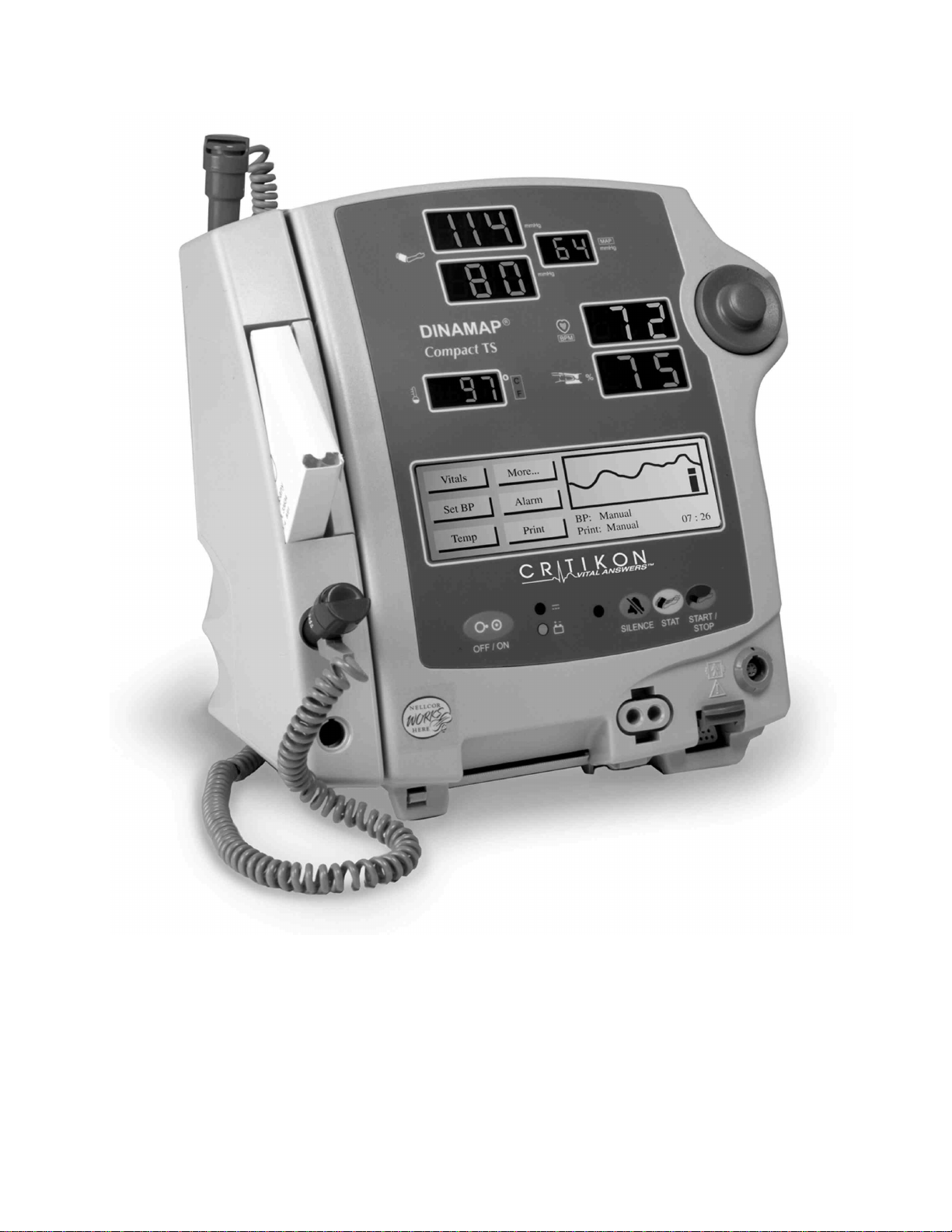
The contents of this document, including all figures and drawings, is proprietary information of
GE Medical Systems, provided solely for purposes of operation, maintenance, or repair of
Dinamap™Compact Monitors.
Dissemination for other purposes or copying thereof without the prior written consent of GE
Medical Systems, Tampa, Florida, is prohibited. Illustrations may show design models;
production units may incorporate changes.
©GE Medical Systems Information Technologies 2001 TAMPA, FL 33614
Printed in the U.S.A. All rights reserved.
Reissues and Updates
Changes occurring between issues are addressed through Change Information
Sheets and replacement pages. If a Change Information Sheet does not
accompany this manual, it is correct as printed.
Errors & Omissions Excepted
If, in the normal use of this manual, errors, or incorrect data are found, please notify:
United States
GE Medical Systems Information Technologies.
4502 Woodland Corporate Boulevard
Tampa, FL 33614
United Kingdom
Monitor House
Unit 3 Cherrywood
Chineham Business Park
Basingstoke
Hants RG24 8WF

3
DINAMAP™Compact Vital Signs Monitor Model TS

4
TABLE OF CONTENTS
1 INTRODUCTION 7
1.1 Scope of Manual 7
1.2 Warranty and Service 7
1.2.1 Packing Instructions8
1.2.2 Service Loan Units 8
1.2.3 Repair Parts 8
1.2.4 Replacement Accessories 9
1.3 Service Centers 9
1.4 Installation and Operation 10
1.5 Warnings & Precautions 10
1.6 Symbol Definitions 10
1.6.1 Safety Symbols 10
1.6.2 Key and Display Symbols 10
1.6.3 Connector Symbols 11
1.7 Electrical, Mechanical & Environmental Specifications 11
2 PRODUCT DESCRIPTION 15
2.1 Introduction 15
2.2 Physical Description 15
2.3 Overall Principles of Operation 19
2.4 Functional Description 19
2.4.1 System Processor 19
2.4.2 Temperature System (TS & T models only) 20
2.4.3 NIBP System 21
2.4.4 Pneumatics System 21
2.4.5 SpO2System (TS & S models only) 23
2.4.6 Power Supply 23
2.4.7 Audio Amplifier 24
2.4.8 Alarm and Communication Interfaces 24
2.4.9 User Controls 25
2.4.10 Displays 25
2.4.11 Printer 26
3 MAINTENANCE 27
3.1 General Maintenance 27
3.1.1 Replacing Fuses 27
3.1.2 Periodic Maintenance27
3.1.3 Care of the Storage Battery 28

5
3.2 Service Modes 29
3.2.1 The Clinician Menu (Service mode 1 2 3 4)31
3.2.2 The Service Menu (Service mode 2 2 1 3)32
3.3 Calibration -Checking & Re-calibrating 36
3.3.1 Checking of NIBP Calibration 36
3.3.2 NIBP Calibration 37
3.3.3 NIBP Pop Off Checking 38
3.3.4 NIBP Pop Off Pressure Calibration 39
3.3.5 Predictive Temperature Calibration Check 40
3.3.6 Predictive Temperature Calibration 40
3.4 Monitor Disassembly 42
3.4.1 Removal of the Front Panel 42
3.4.2 Removal of the Switch board, Display board and Liquid Crystal Display module 44
3.4.3 Removal of the Chassis 46
3.4.4 Removal of the Main Board and Power Supply board from the chassis 47
3.4.5 Removal of the Pump and Pressure Transducer 48
3.4.6 Removal of the Printer 49
3.4.7 Reassembling the Monitor 50
4MANUAL RELEASE TEST PROCEDURE 51
4.1 General 51
4.1.1 Test Equipment 51
4.1.2 Test Conditions 51
4.1.3 Service mode 51
4.2 Test Procedure 52
4.2.1 Power Up Tests 52
4.2.2 External DC Supply and Battery Indication Operation 52
4.2.3 Temperature Requirements 52
4.2.4 Pulse Oximeter Requirements 53
4.2.5 NIBP Requirements 54
4.2.6 Printer Operation 55
4.2.7 Calibration Time Stamp 55
4.3 Manual Release Test Results Sheets 56
5TROUBLE SHOOTING. 58
6TECHNICAL INFORMATION64
6.1 Host Port Connector (rear panel) 64
6.2 Remote Alarm Connector (rear panel) 64
6.3 Accessory Part Numbers 65
6.4 DINAMAP™Compact Service Spares List 69
6.5 Procedural & Error Alarm Code Table 75

6
7GLOSSARY OF TERMS AND ABBREVIATIONS 77
8SERVICE DIAGRAMS 78

7
1Introduction
1.1 Scope of Manual
This Service Manual provides service and parts repair information for the DINAMAP™Compact Vital Signs
Monitor.
This manual is intended for use by service technicians who are familiar with electromechanical devices and
digital and analog circuit techniques.
!
WARNING
To reduce the risk of electric shock, do not remove the instrument’s covers.
Refer servicing to qualified service personnel.
Only trained service technicians should perform repairs on this equipment.
Take particular care when servicing the power supply assembly.
For information about operating the monitor in a clinical environment, refer to the DINAMAP™Compact Vital
Signs Monitor Operation Manual (p/n 776-980.)
1.2 Warranty and Service
The warranty for the product is enclosed with the product in the shipping carton. All repairs on products
under warranty must be performed by or approved by Technical Service personnel. Unauthorized repairs
will void the warranty. Qualified electronic service personnel should repair products not covered by
warranty.
Extended warranties may be purchased for most products. Contact your sales representative for details and
pricing.
If the product fails to operate correctly, or if assistance, or service is required, contact the Technical Support
Department at Critikon. Before doing so, it is helpful to attempt to duplicate the problem and to confirm the
correct operation of all the accessories to ensure that they are not the cause of the problem.
Prior to calling, please be prepared to provide:
??the product name and model number
??a complete description of the problem
and if repair parts or service are necessary:
??the product serial number
??your business name and address, and Critikon Company account number
??a purchase order number if parts or service are to be purchased
??the part number of the required spare parts

8
If your monitor requires warranty, extended warranty, or non-warranty service, call Technical Support and a
representative will assist you. To expedite service where the product has external chassis or case
mechanical damage, please advise the Technical Service representative when you call.
The representative will record all the necessary details and will provide the information, which is required for
all returned products.
Prior to returning the monitor, contact GE Medical Systems Information Technologies:
1-877-274-8456
This service is available Monday to Friday between the hours of 8 am and 7 pm EST excluding holidays.
1.2.1 Packing Instructions
??Remove all hoses, sensors, power cables and the battery from the monitor.
??Only pack the accessories, which you are requested to return, and pack these in a separate bag
within the same carton as the monitor.
??Use the original shipping carton and packing materials, if available.
??Place the monitor in a plastic bag and tie or tape it shut to prevent loose particles entering the
product.
??Pack 4 to 6 inches of padding around all sides of the monitor.
??Use packing tape to securely close the carton.
Insurance is at the customer’s discretion. Any claims for damage must be initiated by the sender.
1.2.2 Service Loan Units
A loan unit is provided on request, at no charge during the service life of the product, while Critikon is
performing the repair. The loaner equipment will be shipped to your site within 2 business days.
??Critikon will pay for shipping the loaner unit to the customer during warranty repairs.
??The customer must pay shipping charges when a loaner unit is issued for a non-warranty repair.
??The customer must pay shipping charges when a loaner unit is returned.
All loaner units must be returned within the time specified otherwise a rental fee may be incurred.
1.2.3 Repair Parts
Repair parts can be ordered from Customer Care via telephone or fax. Complete assemblies such as the
power supply board are available on an exchange basis. Contact Technical Support for details.
Fax: 813-887-2403
Please allow one working day for confirmation of faxed orders. All such orders must contain the following
information:
??Your business name, address and telephone number
??Your fax number
??Your purchase order number
??Your account number.

9
1.2.4 Replacement Accessories
Replacements such as hoses and sensors must be purchased from GE Medical Systems.
Tel: (877) 274-8456
Please have your account number and the reorder / product code available for the item you wish to order.
A table of accessories and replacement part numbers appears in section 6.3.
1.3 Service Centers
For service, repairs or parts information, contact either the following Critikon office or your local Critikon
Sales Representative
GE Medical Systems Information Technologies
4502 Woodland Blvd
Tampa, FL, 33614
877-274-8456
North America

10
1.4 Installation and Operation
For information on the installation and/or operation of the DINAMAP™Compact Vital Signs Monitor,
reference must be made to the DINAMAP™Compact Vital Signs Monitor Operation Manual. This instrument
is to be operated and serviced by authorized personnel only, and only in accordance with the Warnings and
Precautions given in both the DINAMAP™Compact Vital Signs Monitor Operation Manual and this
document.
1.5 Warnings & Precautions
Refer to the safety warnings and precautions detailed in the DINAMAP™Compact Vital Signs Monitor
Operation Manual.
This manual is intended for use by authorized personnel who are familiar with digital and analog electronic
principles and who are also familiar with the operation of the DINAMAP™Compact Vital Signs Monitor.
Disconnect all the power sources before removing covers.
1.6 Symbol Definitions
1.6.1 Safety Symbols
ATTENTION: Read accompanying
documents
Equipment complies with IEC601-1 (1988)
Type B.F.
Defibrillator protected.
1.6.2 Key and Display Symbols
Power Off/On
SpO2 *
Silence Alarms
Predictive
Temperature **
NIBP
Battery Power
STAT
External Power
MAP
Beats Per Minute
* =TS & S models only
** = TS & T models only

11
1.6.3 Connector Symbols
External Alarm Connector
External Comms Port Connector
Fuse
External Power
1.7 Electrical, Mechanical & Environmental Specifications
NIBP
CUFF PRESSURE RANGE: Adult / Pediatric: 0 mmHg to 290 mmHg
Neonate: 0 mmHg to 140 mmHg
DEFAULT TARGET Adult / Pediatric: 178 ± 15 mmHg
CUFF INFLATION: Neonate: 110 ± 15 mmHg
TARGET CUFF INFLATION Adult / Pediatric: 100 to 250 mmHg; 5 mmHg increments
ADJUSTMENT RANGE: Neonate: 100 to 140 mmHg; 5 mmHg increments
BLOOD PRESSURE
MEASUREMENT RANGE: Systolic
mmHg MAP mmHg Diastolic
mmHg
Adult / Pediatric: 30 -245 15 -215 10 -195
Neonate: 40 -140 30 -115 20 -100
BLOOD PRESSURE ACCURACY: Meets AAMI/ANSI SP-10 Electronic or Automated
Sphygmomanometer Standard for Accuracy. (AAMI/ANSI
standard :± 5 mmHg mean error; 8 mmHg standard deviation;
intra-arterial method.)
BLOOD PRESSURE 20 seconds to 45 seconds typical
DETERMINATION TIME: Adult: 120 seconds maximum,
Neonate: 85 seconds maximum.
PULSE RATE DETERMINATION: Adult / Pediatric: 30 -200 BPM
Neonate: 30 -200 BPM
PULSE RATE ACCURACY: ± 3.5 percent
OVERPRESSURE CUT-OFF: Adult / Pediatric 300 -330 mmHg
Neonate 150 -165 mmHg
Predictive Temperature Determination (TS & T models)
RANGE: Max. 42.2 ?Celsius 108.0° Fahrenheit
Min 31.1?Celsius 88.0° Fahrenheit
PROBE ACCURACY: ?0.1oC± 0.2oF

12
PREDICTIVE TEMPERATURE ?0.6oC, 36.1-39.4oC± 1oF, 97-103oF
ACCURACY : UNSPECIFIED < 36.1OC, > 39.4 OC
UNSPECIFIED < 97 OF, > 103 OF
DETERMINATION TIME: 30 seconds typical; 60 seconds maximum
SpO2 (TS & S Model)
OXYGEN SATURATION
RANGE: 0 to 100%
SATURATION ACCURACY: 0% to 69%: unspecified
ADULT ACCURACY (70-100%)
Nellcor Puritan Bennett™Sensor Accuracy
OXICLIQ-P Pediatric sensor 2.5 digits
OXIBAND Pediatric/infant sensor 3.0 digits
DURA-Y ear clip 3.5 digits
OXISENSOR II D-20 Pediatric sensor 3.5 digits
OXICLIQ-N neonatal/adult sensor 2.5 digits
REFLECTANCE sensor 3.5 digits
DURASENSOR adult 3.0 digits
OXIBAND adult/neonatal sensor 3.0 digits
DURA-Y multisite sensor 3.0 digits
OXISENSOR R-15 adult nasal sensor 3.5 digits
OXISENSOR II D-25 adult sensor 2.0 digits
OXICLIQ-A adult sensor 2.5 digits
OXISENSOR II N-25 neonatal/adult sensor 2.0 digits
OXISENSOR II I-20 infant sensor 2.0 digits
OXISENSOR II D-25L adult sensor, long cable 2.0 digits
Neonatal Accuracy:
When sensors are used on neonatal subjects as recommended, the specified accuracy range is increased
by ?1 digit to account for the theoretical effect on oximeter measurements of fetal hemoglobin in neonatal
blood (e.g., N –25 accuracy on neonates is ?3, rather than ?2.)
Note: Refer to NELLCOR PURITAN BENNETT sensor specifications.
PULSE RATE DETERMINATION:20 BPM -250 BPM +/-3 beats
SATURATION PITCH INDICATOR: Pitch changes with saturation.
Volume selectable from 0 (off) to 9.
WAVEFORMS: Pulse Plethysmograph waveform on LCD gain compensated
SENSOR DISCONNECT / The monitor will detect the attachment or disconnection
DISCONNECT FROM PATIENT: of a sensor from the patient within 5 seconds.
PULSE DETECTION: The monitor will detect a pulse or enter a no signal state within 15
seconds of being attached to the patient.

13
LOSS OF PULSE:The monitor will detect loss of pulse from patient and
enter a no signal state within 10 seconds.
Mechanical
DIMENSIONS:Height: 9.1 in (23.0 cm)
Width: 7.3 in (18.5 cm)
Depth: 6.9 in (17.5 cm)
WEIGHT including battery: 8.3 lb (3.75 kg)
MOUNTINGS:Self-supporting on rubber feet or pole mountable.
PORTABILITY: Carried by recessed handle or pole mounted.
CLASSIFICATION INFORMATION:• Mode of Operation -Continuous
• Degree of Protection against harmful ingress of water: (See
IPX1 definition).
Power Requirements:
POWER CONVERTER: Protection against electrical shock -Class 1
INPUT VOLTAGE:115 / 230 VAC, 50 / 60 Hz (nominal),
90 ~ 264 VAC, 47 ~ 63 Hz (range)
MONITOR: Protection against electrical shock -Class 1
INPUT VOLTAGE: 24 VDC (nominal), 12-30 VDC from supplied power converter
EXTERNAL DC LINE FUSE:T3.15A 250 VAC
BATTERY: 12 volt, 2.3 amp-hours.
Minimum operation time: 2 hours (5 minute auto cycle with adult
cuff at 25°C with power save mode enabled) from full charge.
Time for full recharge: 8 hours from full discharge
Environmental
OPERATING TEMPERATURE: + 5° C to + 40° C (+ 41° F to + 104° F)
OPERATING ATMOSPHERIC
PRESSURE RANGE: 700 to 1060 hectoPascal
STORAGE TEMPERATURE: –20° C to + 50° C (–4° F to + 122° F)
STORAGE / TRANSPORTATION
ATMOSPHERIC PRESSURE: 500 to 1060 hectoPascal
HUMIDITY RANGE: 0 % to 95 % non-condensing
RADIO FREQUENCY Complies with IEC Publication 801-3 (Draft 7, second edition)
ELECTROMAGNETIC IMMUNITY: 3.0V/m, modulation 80% AM @ 1kHz, frequency range
26.0~1000.0Mhz

14
This product conforms with the essential requirements of the Medical Device Directive.
Accessories without the CE Mark are not guaranteed to meet the Essential
requirements of the Medical Device Directive.
The DINAMAP™Compact monitor is protected against vertically falling drops of water
and conforms to the IEC 529 standard at level of IPX1. No harmful effects will come of
vertically falling drops of water making contact with the monitor.
0086
IPX1

15
2PRODUCT DESCRIPTION
2.1 Introduction
The DINAMAP™Compact series of monitors are portable devices, provide non-invasive determination
systolic and diastolic blood pressure, mean arterial pressure (MAP), pulse rate, predictive temperature and
blood oxygen saturation for neonatal and adult/Pediatric patients. Certain model variants are not equipped
with all functions. The monitors are mains or battery operated, and are primarily intended for use in hospital
acute care settings such as Day Surgery, Accident & Emergency, ITU, High Dependency Units, Labor and
Delivery, GI/Endoscopy, and Medical/Surgical Units.
2.2 Physical Description
Each monitor is supplied with an accessory pack. The contents of the pack vary according to model and are
listed below:
Model: DINAMAP™Compact BP Monitor
Qty Description
1DINAMAP™Compact Monitor with integral printer
1AC-DC Power Converter
2Mains power leads
1Rechargeable Battery
1Cuff, Standard Adult
1Pneumatic Hose, 12 ft., Standard Adult
2Printer paper rolls
1Operating Instruction Manual
Model: DINAMAP™Compact TS & T Monitors are supplied as above, with the addition of:
Qty Description
1Nellcor Puritan Bennett™ Finger sensor
1Nellcor Puritan Bennett™ sensor extension cable
Models TS and T are supplied with the Predictive Temperature Kit. This is comprised of the following
items:
Qty Description
1Oral Temperature Probe
1Probe holder accessory
2Pack of 20 probe covers
1Instruction sheet

16
Rear Panel Connections
1
2
6
5
4
3
T3.15A 250V
1
POLE CLAMP
Used to clamp the monitor to a pole or stand.
2
BATTERY COVER
Securely retains and protects the internal battery.
3
EXTERNAL POWER
Connection socket for the supplied external power
converter ONLY.
4
FUSE HOLDER
External power source line fuse holder.
5
DATA INTERFACE
CONNECTOR
Host communications port: 15 way D-type RS232 serial
port for use with equipment conforming to IEC-601 only.
6
REMOTE ALARM
CONNECTOR
Remote Alarm port with both normally open and
normally closed isolated contacts for use with equipment
conforming to IEC-601 only. (if so equipped)

17
Front Panel Controls & Indicators (TS Model shown)
17
15
16
7
10
21
11
8
9
19
18
14
13
12
23
24
2526
27
20
22
7
This push button switch controls the ON/
OFF state of the monitor. Push for power
ON and again for power OFF.
18
This 3 digit LED indicates SpO?
Oxygen Saturation in %. =
8
This green LED indicates the external
power and battery charging status of the
monitor.
19 PULSE BPM
DISPLAY This 3-digit yellow LED display
shows pulse rate in Beats Per
Minute.
9
This yellow LED indicates operation and
charge status of the internal battery. 20
This yellow LED flashes, indicating
real-time pulse rate measurements
are derived from the SpO2signals.
10 ROTOR
CONTROL This is used to highlight and select items in
the LCD menus. If the monitor is OFF,
pushing it will switch the monitor ON.
21
This 4 digit red LED Display
indicates the measured
Temperature.
11 LCD This panel displays all alarms, user
interface messages & configuration
options.
22 °C °F DISPLAY These indicate that Temperature is
being displayed in degrees Celsius
or Fahrenheit.
12
Press this key to begin or halt an NIBP
determination. The key also cancels STAT
mode.
23 TEMP. PROBE
CONNECTOR Plug the predictive temperature
probe cable into this socket.
13
Press this key to begin or halt operation of
the STAT mode of NIBP monitoring. 24 SpO2SENSOR
CONNECTOR Attach the SpO2sensor extension
cable to this socket. =
14
This switch alternately mutes & enables
the audio alarm. When pressed once
(SILENCE ON) the switch lights indicating
audible alarms have been silenced.
25 CUFF
CONNECTOR Insert the NIBP Cuff hose into this
connector.
15 SYSTOLIC
PRESSURE This 3 digit red LED display indicates the
measured systolic B.P. in mmHg. 26 LIGHT SENSOR Automatically measures ambient
light to set LED display intensity.
16 DIASTOLIC
PRESSURE This 3 digit red LED display indicates the
measured diastolic B.P. in mmHg. 27 PRINTER DOOR Open this door to gain access to the
paper.

18
17
This red LED display indicates the
measured mean arterial B.P. in mmHg. It
also shows instantaneous cuff pressure
during an NIBP determination.
=TS & S models only

19
2.3 Overall Principles of Operation
This section of the manual describes the principles of operation of the DINAMAP™Compact monitor. The
section is arranged to give an overall description of the instrument, the following sections then detail each of
the functional systems. For full assembly drawings, circuit diagrams and parts lists of the component circuit
boards, refer to section 8of this manual. The system block diagram of the DINAMAP™Compact monitor is
shown in drawing 8600EB.
Patient vital signs can be measured by a variety of electronic sensors, including oscillatory pressure sensors
for Non-Invasive Blood Pressure measurement. Both the DINAMAP™Compact T and TS models are
provided with a predictive temperature parameter determination. The Compact TS model is also equipped
with a Nellcor Puritan Bennett™Blood Oximetry module enabling oxygen saturation and heart rate to be
determined from information received via a finger sensor.
Operator access is via buttons and the rotor located on the front panel. A liquid crystal graphics display
module provides the user with menu, alarm and status information as well as a plethysmograph display or a
record of previous measurements. Parameter information is presented by multiplexed seven segment LED
displays and discrete LED indicators. A thermal printer provides hard copies of patients vital signs either
automatically or on demand. A built-in speaker and piezo-electric sounder advise the user of pulse signals
and alarm conditions.
The monitor is designed to operate from AC mains via the supplied power converter, or from an internal
rechargeable battery. The external AC power converter rectifies the mains to produce a raw DC supply
which is regulated internally to provide the DC operating power. The external raw DC source is employed to
charge the internal batteries. The real time clock and user monitor settings are maintained by an internal
rechargeable NiCd backup battery.
The monitor includes a pneumatics system required for NIBP operation. NIBP determinations are made by
pumping up the air pressure in a restrictive cuff and monitoring the oscillatory signals in the system as the
pressure is released. Large deflation steps are employed for NIBP and the system processor interpolates
measurements between steps. The pneumatic system then regulates operation of the pneumatic pump and
valves. An overpressure sensor provides independent protection against over-inflation. Protection against
deflation failure is inherent in the design; the valve and pneumatic system being designed to auto-deflate
the system in the event of power fail or alarm situations.
Blood Oximetry (SpO2) determinations (model TS only) are made using a proprietary module from Nellcor
Puritan Bennett™, which communicates the parameter measurements to the system processor via an
internal serial port.
Predictive temperature measurements are based on a 3 or 12-minute mercury in glass reference. Predictive
Temperature probes can be connected to the monitor to provide an analog signal representing the
measured temperature. An A/D converter then digitizes this analog signal; this information is then
interpreted by the system processor and displayed for viewing.
2.4 Functional Description
The functions of the DINAMAP™Compact monitor can be separated into eleven discrete parts. The
following paragraphs describe each of the Monitors, with full circuit diagrams provided in section 8.
2.4.1 System Processor
The system processor is based on 68302 microprocessor IC22 on the Main Board. A master 19.6608 MHz
clock generated by XL1 exits the system processor at pin 98 and is divided by 16 inside binary ripple

20
counter IC36 to provide the 1.23 MHz ADC clock. Communication between microprocessor IC22 and all bus
devices is provided by a 24-bit address bus, 8-bits data bus and the three wire serial peripheral interface
(SPI) bus. The system processor is equipped with a watchdog timer and reset circuit.
The system program is stored in a 4 Mbit FLASH memory IC28 as 512k by 8 bit words. Program memory is
provided by a low power 1 Mbit SRAM IC32 formatted as 128k by 8 bit words. Non-volatile settings are
stored in an EEPROM IC26 which talks to a dedicated serial port on the system processor. All bus devices
are powered from the +5VD digital supply, except for the RAM that is also powered from the VRAM supply
when the system is in “standby” mode.
Should the software detect a system fault or fail to reset its watchdog timer, the system processor will output
a logic low level on its watchdog output WDOG. This is latched as FAILSAFE by the output of the bistable
formed by IC31, allowing the output of the relaxation oscillator IC1 to pass through IC4 to sound the piezo
sounder LS1. The FAILSAFE signal is also used to disable the isolated power supply module PM100.
The power supply board battery backup voltage BATT_BACKUP, derived from either NiCd battery or an
external supply, appears on the supervisory circuit IC35. This supervisory circuit has two functions. First, it
generates Reset and Halt signals for the system processor when the 5 volt power supply powers on and off
respectively. Secondly, it controls transistor TR8, allowing the 5 volt line to power the RAM chip IC32 and
PIC when the system is “on”, or the BATT_BACKUP to power the RAM and the PIC when the system is
“off”. This allows values to be saved in the otherwise volatile RAM and to maintain the low power standby
mode of the PIC.
Additional control signals from the system processor are decoded by IC16, which generates seven chip
select lines and IC17 which generates latch outputs for the LED display drivers. The data bus D0 ~ D7 is
filtered by inductors L12~19 to produce a buffered data bus DB0 ~ DB7 for the display drivers.
There is also a PIC micro-controller IC5 on the power supply board 8620AB, which has its own independent
watchdog, reset circuit and provides the real-time clock function. The PIC provides control of PSU status,
battery charging, printer and alarm/annunciator audio output. Communications between the system
processor and the PIC are continually monitored in order to provide additional fail-safe security for the
monitor. All measurement, alarm and communications ports of the instrument are isolated to IEC601.
2.4.2 Temperature System
The temperature system for the Model DINAMAP™Compact Monitor for reading predictive thermistor probes
is located on the Main Board.
If a thermistor probe is used, the resistance of the probe varies in relation to temperature. The probe
resistance is effectively in parallel with R63 and therefore a change in temperature results in a change in
voltage applied to input selector IC19. The selected input voltage from IC19 is connected to the voltage to
frequency converter (VFC) IC18. The frequency of the square wave output from the VFC varies
proportionately to the input voltage. The output signal is isolated through opto-coupler PC2 and enters the
system processor, as PRED_TEMP_F. The processor receives the square wave signal and determines the
temperature by counting the number of edges received per unit interval.
Through the application of a software algorithm, the system processor provides two select lines TEMP_SEL0
and TEMP_SEL1. These are isolated by opto-isolators PC3 and PC4 and used to control the input selector
IC19, allowing the appropriate resistor tree to be selected. There are four selectable channels, two providing
calibrations points, a third used for probe type detection and the fourth for the thermistor measurement.
The probe type is determined by measurement of the frequency produced by the VFC from a DC input
derived from resistor tree R59-R61; for an oral probe this produces a frequency equivalent to 42 degrees
Celsius, Rectal probes short out R61 and hence change the frequency slightly. The software is capable of
determining which probe type is attached and hence selects the appropriate measurement mode.
Table of contents
Other GE Medical Equipment manuals
Popular Medical Equipment manuals by other brands

Arjo
Arjo IndiGo Instructions for use

BeaconMedaes
BeaconMedaes Lifeline Installation, operation and maintenance instructions

Braun
Braun Aesculap Reusable trocar system 5 mm Instructions for use/Technical description

Nasco
Nasco Life/form LF00980U instruction manual

Etac
Etac molift MRS Duo user manual

Bionet
Bionet BM3 user manual