GE OEC 9800 Operating and maintenance manual

OEC 9800 Installation Procedure
1
Service
Periodic
Contents
Schematics
Illustrated
Installation
Contents
Overview.........................................................................................................................................................................3
Unpacking the System ..................................................................................................................................................3
Depalletization Performed By .......................................................................................................................................4
Installation Report .........................................................................................................................................................5
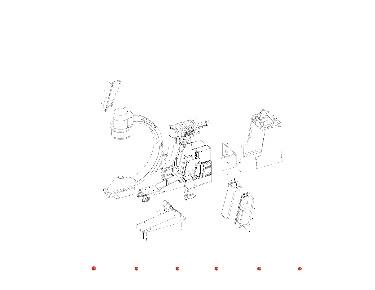
C-Arm Damage Inspection ...........................................................................................................................................5
Workstation Damage Inspection...................................................................................................................................5
Inventory of Customer Items.........................................................................................................................................6
C-Arm Items ..............................................................................................................................................................6
Workstation Items......................................................................................................................................................6
Optional Equipment...................................................................................................................................................6
Installation Procedures .................................................................................................................................................6
Cover Removal, Internal & Cable Inspection, Partial Setup..........................................................................................7
Mechanical Checks.....................................................................................................................................................10
The Power Cord Assembly .........................................................................................................................................10
Isolation Transformer Strapping .................................................................................................................................12
Power ON System ......................................................................................................................................................16
Line Voltage Regulation..............................................................................................................................................20
C-Arm Control Panel and Foot/handswitch Check .....................................................................................................21
Workstation Keyboard Check .....................................................................................................................................24
Backup the Configuration Files...................................................................................................................................25
Options .......................................................................................................................................................................26
Cine Archive Disk Test ............................................................................................................................................26
High Capacity Disk Test ..........................................................................................................................................26
VCR Test.................................................................................................................................................................26
IR Transmitter Test..................................................................................................................................................26
Digital Hardcopy Camera test..................................................................................................................................27
Instant Film/Paper (Onboard) Printer.......................................................................................................................27
Thermal Printer Test................................................................................................................................................27

OEC 9800 Installation Procedure
2
Service
Periodic
Contents
Schematics
Illustrated
Installation
DICOM ....................................................................................................................................................................27
9800 FluoroTrak...................................................................................................................................................28
Radiographic Beam Alignment Test ...........................................................................................................................32
Film Exposure .........................................................................................................................................................32
50 mm x 50 mm Field Verification ...........................................................................................................................33
Centering.................................................................................................................................................................33
Normal Field Verification .........................................................................................................................................33
MAG1 Field Verification...........................................................................................................................................34
MAG2 Field Verification...........................................................................................................................................34
Pass or Fail .............................................................................................................................................................35
Preparing the Pallet for Return ...................................................................................................................................36
Reporting ....................................................................................................................................................................36
Reporting for Domestic Systems .............................................................................................................................36
Reporting for International Systems ........................................................................................................................37
Installation Comments ................................................................................................................................................37

OEC 9800 Installation Procedure
3
Service
Periodic
Contents
Schematics
Illustrated
Installation
Overview
Access the latest version of the 9800 Installation Report/Checklist, 00-879060, and use it in conjunction with this document.
Follow the installation procedures in the order written, and note that the sections of the procedures correspond to the same section
title in the Report/Checklist.
Unpacking the System
Note: The Workstation and C-Arm ramps are usually located on top of the Workstation’s enclosure. However, if the system is
shipped by air freight, the C-Arm ramp is typically stored inside the C-Arm enclosure.
1. Before unpacking, inspect the shipping enclosure/boxes for damage and report to the shipper if available. Note any damage in
the Installation Comments section of the Report/Checklist, 00-879060.
2. Remove the banding from the Workstation and C-Arm shipping enclosure/pallets. See Figure 1 (next page).
3. Remove the ramps from the top of the Workstation enclosure. See Figure 1 (next page).
4. Remove the cardboard cap and lift the cardboard from the top of both enclosures. Discard both cardboard items.
5. Remove the clear plastic covers from the Workstation and the C-Arm.
6. Use the depalletization instructions located on the Workstation cable hanger (00-881509-XX) and C-Arm’s cross-arm (00-
881508-XX) to depallet the Workstation and the C-Arm.
7. Record the results in the latest version of the 9800 Installation Report/Checklist, 00-879060.

OEC 9800 Installation Procedure
4
Service
Periodic
Contents
Schematics
Illustrated
Installation
Figure 1 −
−−
−9800 C-Arm and 1k x 1k Workstation Enclosures
Depalletization Performed By
Put a check in the appropriate box in the table in the corresponding section of the 9800 Installation Report/Checklist, 00-879060
(latest version). Note in the Installation Comments section of the Report/Checklist if only a Workstation or C-Arm was
depalletized.

OEC 9800 Installation Procedure
5
Service
Periodic
Contents
Schematics
Illustrated
Installation
Installation Report
Visually inspect the system according to the separate C-Arm and Workstation matrices in the 9800 Installation Report/Checklist,
00-879060. Each matrix lists the area to inspect in the left-most column, and the possible condition on the top row.
The areas to inspect are grouped according to the larger visible, easily accessible assemblies and/or modular parts of the system.
Each inspection of an assembly area should include its visible component parts and sub-assemblies; for example, inspection of the
Image Intensifier should account for its cover, handles, screws, etc.
C-Arm Damage Inspection
Inspect the C-Arm for damages and record the information in the corresponding section of the latest version of the OEC 9800
Installation Report/Checklist.
Workstation Damage Inspection
Inspect the Workstation for damages and record the information in the corresponding section of the latest version of the OEC 9800
Installation Report/Checklist.

OEC 9800 Installation Procedure
6
Service
Periodic
Contents
Schematics
Illustrated
Installation
Inventory of Customer Items
Inventory the accessory kits for the C-Arm and Workstation to locate the items listed in the table in the corresponding section of
the Report/Checklist. Leave these items for the customer when the installation is complete. If a Workstation is installed alone,
then items related to the C-Arm will not be present.
C-Arm Items
Write the quantity present or missing in the appropriate column in the C-Arm Items table in the Report/Checklist.
The Mobile C-Arm keys are attached to one of the binder rings inside the 9800 C-Arm Operator’s Guide. Give the keys to the
customer once the installation has been completed.
Workstation Items
Write the quantity present or missing in the appropriate column in the Workstation Items table in the Report/Checklist.
Optional Equipment
In the Optional Equipment table, put a check mark by each option shipped with the system to confirm that the option is present.
If no options are provided, check the No Options checkbox only. Write in any options that are present but not listed.
Installation Procedures
Follow these installation procedures in the order written to get the 9800 system operational, and record the information asked for
in the corresponding sections of the OEC 9800 Installation Report/Checklist, 00-879060 (access the latest version).

OEC 9800 Installation Procedure
7
Service
Periodic
Contents
Schematics
Illustrated
Installation
Cover Removal, Internal & Cable Inspection, Partial Setup
Note: Observe electrostatic discharge safety procedures.
1. Check the antistatic drag cable on the Workstation and the C-Arm.
2. Inspect the interconnect cable, AC power cable and the high voltage cable for wear, abrasion and bent or broken pins.
3. Remove Workstation covers and inspect the internal cables and PCB seating. Look for loose parts. See Figure 2 (next page).

OEC 9800 Installation Procedure
9
Service
Periodic
Contents
Schematics
Illustrated
Installation
6. Install the skin spacer on the C-Arm.
7. Remove the C-Arm’s covers and inspect the internal cables and PCB seating. Look for loose parts. See Figure 3.
8. Verify the eye-bolts are removed from underneath the C-Arm’s T-base (near the wheels on each side).
Figure 3 −
−−
−Remove the C-Arm Covers (covers arranged for illustration purposes)

OEC 9800 Installation Procedure
10
Service
Periodic
Contents
Schematics
Illustrated
Installation
Mechanical Checks
1. Check the entire range of Wig-Wag movement.
2. Check the entire range of Horizontal Cross-arm movement.
3. Check the entire range of Flip-Flop/C-arm pivot.
4. Check the entire range of C-arm orbital rotation.
5. Check the entire range of L-arm rotation (N/A on Super C).
6. Check the C-Arm Brake Pedal operation (forward lock, neutral and rear lock) positions.
7. Check the entire range of C-Arm steering.
8. Check the Workstation Brake Pedal operation (up, neutral, down) positions.
The Power Cord Assembly
There are two power cord assemblies. The two Power Cord assemblies are wired differently to accommodate the different
voltages. The correct power cord assembly must be used for proper operation of the system. One power cord assembly is used for
voltage sources ranging from 100 - 127 VAC and different power cord assembly is used for voltage sources ranging from 200 –
250 VAC.

OEC 9800 Installation Procedure
11
Service
Periodic
Contents
Schematics
Illustrated
Installation
TB1
200-250 VAC CORD ASM
BRN BRN
CB1
BRN
WHT/BRN
BLU
10A
10A
BLU
1
BLU
3
5
GRN/YEL
RESET ONLY
1
5
3
9
6
8
E1
DS1
GREEN LAMP
AC POWER
20 FT/30 FT CORD
MOUNTING PLATE
BRN BRN BRN
CB1 RESET ONLY CB2 RESET ONLY
MOUNTING PLATE
GREEN LAMP
AC POWER
DS1
BLU
BLU
GRN/YEL
BLU
1
3
5
2
4
6
1
3
2
4
1
3
2
4
1
3
5
6
9
8
E1
20 FT CORD
TB1
100-127 VAC CORD ASM
20A
20A 10A
Figure 4 −
−−
−Power Cord Asm.
Note: The factory has attempted to provide the proper power cable plug assembly, but due to different international
requirements, the proper power plug assembly may not be furnished. If assistance is required, contact GE OEC Medical
Systems, Inc.
WARNING Electrical circuits inside the equipment use voltages that are capable of causing serious injury
or death from electrical shock. Use appropriate precautions.

OEC 9800 Installation Procedure
12
Service
Periodic
Contents
Schematics
Illustrated
Installation
Isolation Transformer Strapping
To match the nominal wall receptacle voltage to the input (primary) of the isolation transformer, you must select the correct tap
voltage for the wires on Primary 1 (BRN, WHT/BLU) and the wires on Primary 2 (WHT/BRN, BLU).
Figure 5 −
−−
−Partial Schematic Diagram of the Isolation Transformer
1. Connect the interconnect cable to the C-Arm and plug the power cord into the wall outlet.
2. If the system is equipped with a 100-127 VAC power cord, measure the voltage from the BRN wire to WHT/BLU on T1
primary and record the results in the table on p. 5 of the Report/Checklist.
If the system is equipped with a 200-250 VAC power cord, measure the voltage from the BRN wire to WHT/BLU on the T1
primary and record the results in the table on p. 5 of the Report/Checklist.
Note: If the voltage measured in step one measures from 100 –127 VAC use Table 1 (next page). If the voltage measured in step
one measures between 200 –250 VAC use Table 2 (next page).
For example, if the voltage measured equals 112 VAC, use Table 1 (100 – 127 VAC). The correct voltage taps would be

OEC 9800 Installation Procedure
13
Service
Periodic
Contents
Schematics
Illustrated
Installation
found in the row described by voltage range 110.0 to 115.9. Connect the wires as described in that row.
For Example: If the voltage measured equals 224 VAC, use Table 2 (220 – 250 VAC). The correct voltage taps would be
found in the row described by voltage range 220.0 – 231.9 VAC. Connect the wires as described in that row.
3. Find the corresponding voltage range in the first column of the table and determine the voltage taps.
Table 1 (100 - 127 VAC )
If the AC line
voltage
determined in
ste
p
1 is
Connect
WHT/BLU
wire to
Primar
y
#1
Connect BRN
wire to Primary
#1 terminal…
Connect BLU
wire to
Primary #2
terminal…
Connect
WHT/BRN
wire to
Primar
y
#2
104.0 to 109.9 6 113 6 113
110.0 to 115.9 0113 0113
116.0 to 121.9 6 125 6 125
122.0 to 128.0 0125 0125
0 101 125 6 113
PRIMARY 1PRIMARY 2
6 113 0 101 125
WHT/BLU BRNBLU WHT/BRN
Figure 6 −
−−
−Isolation Transformer (T1) Tap Locations for 112 VAC

OEC 9800 Installation Procedure
14
Service
Periodic
Contents
Schematics
Illustrated
Installation
Table 2 (200 – 250 VAC)
If the AC line
voltage
determined in
ste
p
1 is
Connect
WHT/BLU
wire to
Primar
y
#1
Connect BRN
wire to Primary
#1 terminal…
Connect BLU
wire to Primary
#2 terminal…
Connect
WHT/BRN
wire to
Primar
y
#2
196.0 to 207.9 0 101 0 101
208.0 to 219.9 6113 6113
220.0 to 231.9 0 113 0 113
232.0 to 243.9 6125 6125
244.0 to 256.0 0 125 0 125
4. With all options switched ON and the system fully booted, measure the following voltages at the primary and secondary of the
isolation transformer (T1) and verify that they meet the specification. Record the measured value in the corresponding table in
the Report/Checklist.
Ref Transformer winding From To Spec
A Primary 1 winding WHT/BLU BRN Receptacle VAC
B Primary 2 winding BLU WHT/BRN Receptacle VAC
C Secondary 1 CT AC1 119 VAC ±3.0
D Secondary 1 CT AC2 119 VAC ±3.0
E Secondary 2 RTN AC 119 VAC ±3.0

OEC 9800 Installation Procedure
16
Service
Periodic
Contents
Schematics
Illustrated
Installation
Power ON System
1. Place the C-Arm's keyswitch in the ON position (clock-wise) and then place the Workstation's power switch in the ON
position. Verify that the Workstation and C-Arm complete their software boot and initialization with no errors reported on the
displays.
2. Verify that the Workstation's elapsed time meter is functional.
3. Verify that the cooling fans are operating on both the Workstation and the C-Arm.

OEC 9800 Installation Procedure
20
Service
Periodic
Contents
Schematics
Illustrated
Installation
4. Verify that the X-ray tube's anode is rotating by listening for a "whirring" sound.
5. Verify operation of the vertical column lift switches.
6. Press and hold a FAST STOP switch while verifying that vertical column operation is disabled, then release the switch and
verify that X-ray generation is disabled and the message FAST STOP ACTIVATED is displayed on the C-Arm's Control
Panel display. Reboot the system by placing the Workstation's power switch in the OFF position for five seconds and then
back to ON.
7. Turn the C-Arm's keyswitch to the STANDBY position (counter-clockwise) and verify that vertical column operation is
disabled, X-ray generation is disabled and the message KEYSWITCH IN STANDBY - XRAYS AND LIFT DISABLED
scrolls across the C-Arm's Control Panel display.
8. Verify the ambient light sensor works by covering it and verifying that the monitor dims.
Line Voltage Regulation
WARNING This procedure produces high energy X-rays. Take the appropriate precautions. Because of the
high radiation output produced, non-service personnel should not be present in the room during
the following test.
1. Measure the wall outlet voltage (Vn) or use the value measured in the Isolation Transformer Strapping procedure. Write the
measured value in the corresponding section of the Report/Checklist.
2. While taking a radiographic exposure at 100 kVp @ 300 mAs, measure the wall outlet voltage (Vl) again. Write the measured
value in the corresponding section of the Report/Checklist.
3. Use the following formula to calculate the percentage of line voltage regulation and record the result in the corresponding
section of the Report/Checklist.
Line Regulation =
()
100 ×−Vn Vl
Vl = % Line Voltage Regulation
4. If the results above do not fall within the range of 0 - 15 %, note this in the Report/Checklist, and inform the hospital
administration that they will need to correct this problem. Note this also on the FSR or Case.
Table of contents
Other GE Medical Equipment manuals
Popular Medical Equipment manuals by other brands

Storz
Storz 11301D4 Instructions for use

Aspen Medical Products
Aspen Medical Products Vista CTO quick start guide

SYMBYX
SYMBYX BIOME DuoCare 904 quick start guide

College Park
College Park Odyssey K3 Technical instructions

Orliman
Orliman OP1181 INSTRUCTIONS FOR USE AND PRESERVATION

Air Techniques
Air Techniques ProVecta 3D Prime installation instructions