GE TruTrak+ 3900 User manual

GE Healthcare
3900/3900P Pulse Oximeter
TruTrak®+
User’s Manual
♥


GE Healthcare
3900/3900P Pulse Oximeter
TruTrak®+
User’s Manual
♥
60 0-0006-406
March 200

Important
Rx Only (USA)
Attention! Consult the accompanying instructions before using this
device.
The safety, reliability, and performance of this device can be assured only under
the following conditions:
• If it is used according to the accompanying operating instructions.
• If fittings, extensions, read ustments, changes, or repairs are carried out by
agents authorized by Datex-Ohmeda.
• If it is used in buildings having ground equalization wiring that complies with
relevant local standards and regulations.
This device must be cleaned and checked periodically. Do not use a defective
device. Parts that are broken, missing, plainly worn, distorted, or contaminated
should be replaced immediately. If repair or replacement becomes necessary,
request service advice from Datex-Ohmeda. Do not repair this device or any of its
parts other than in accordance with written instructions provided by Datex-
Ohmeda.
The user of this device shall have the sole responsibility for any malfunction that
results from improper use, faulty maintenance, improper repair, unauthorized
service, damage, or alteration by anyone other than Datex-Ohmeda.
Trademarks
Datex®, Ohmeda®, OxyTip®, PerfTrak®, TeleOximetry®, TruTrak®, and PIr® are
the property of GE Healthcare Finland Oy. All other product and company names
are the property of their respective owners.
0537
GE Healthcare Finland Oy
Helsinki, Finland
+358 10 394 11
www.gehealthcare.com
© 2005 General Electric Company. All rights reserved.

Table of Contents
i
1/Overview
Product description.....................................................................................................................................1-1
Intended use........................................................................................................................................1-1
TruTrak+ technology.......................................................................................................................1-1
PIr pulsatile value............................................................................................................................1-2
Other features.....................................................................................................................................1-2
Functional components................................................................................................................1-3
Principles of operation..................................................................................................................1-4
Calibration..............................................................................................................................1-5
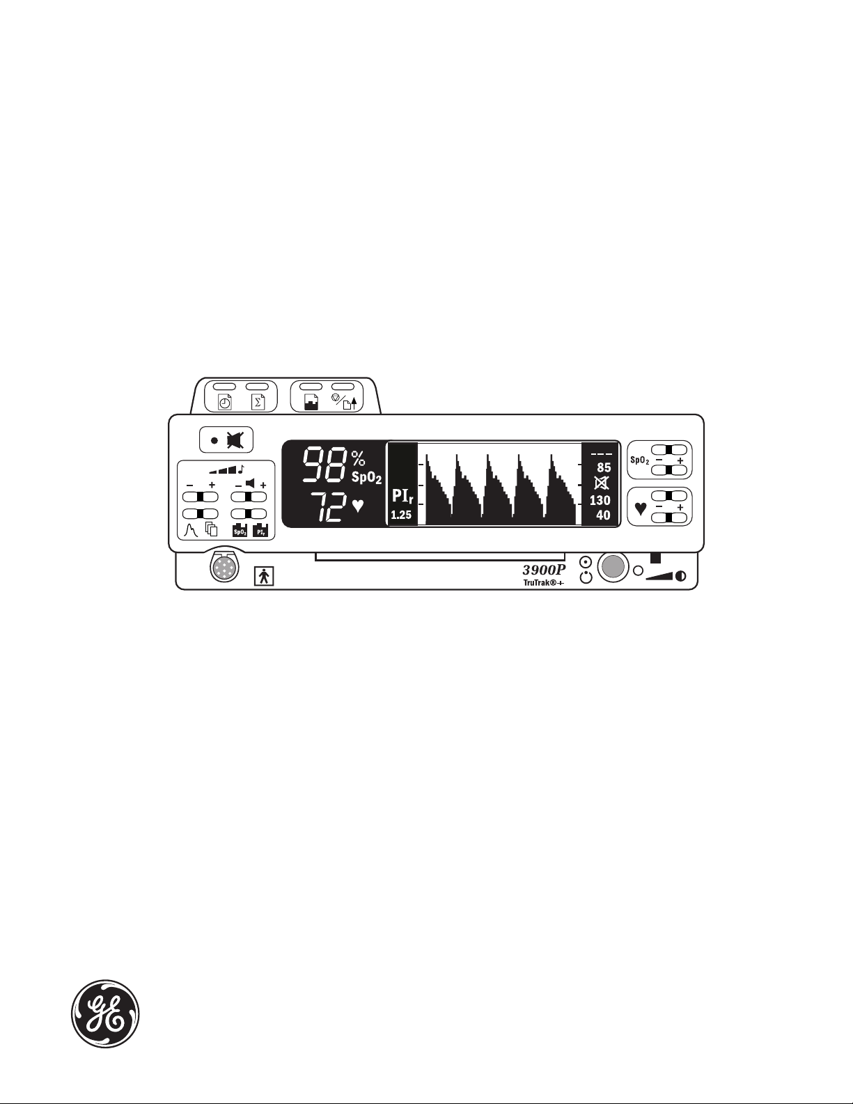
Front panel.......................................................................................................................................................1-6
Alarm silence button......................................................................................................................1-7
Alarm silence........................................................................................................................1-7
All mute....................................................................................................................................1-7
Numeric display...............................................................................................................................1-7
Graphic display.................................................................................................................................1-8
SpO2 alarm limits, high and low............................................................................................1-9
Pulse rate alarm limits, high and low..................................................................................1-9
Display contrast ad uster..............................................................................................................1-9
Power/Standby button/AC power light..............................................................................1-9
Battery operation.................................................................................................................1-9
Carrying handle.............................................................................................................................1-10
Sensor connector...........................................................................................................................1-10
Screen option buttons.................................................................................................................1-10
Pulse beep volume button.......................................................................................................1-11
Alarm volume button..................................................................................................................1-11
Printer..................................................................................................................................................1-11
Rear panel......................................................................................................................................................1-12
Power entry module....................................................................................................................1-12
Equipotential ground connector...........................................................................................1-12
Product information label........................................................................................................1-12
Mode Switch....................................................................................................................................1-12
RS-232 serial/analog connector.............................................................................................1-12
Precautions....................................................................................................................................................1-13
Warnings............................................................................................................................................1-13
Failure of operation........................................................................................................1-13
Data validity........................................................................................................................1-13
Explosion hazard..............................................................................................................1-13
Electrical shock hazard................................................................................................1-13
Electrical shock and flammability hazard........................................................1-14
Patient safety.......................................................................................................................1-14
Patient safety (sensors)..................................................................................................1-14
Patient safety (modem).................................................................................................1-14
RS-232 system interconnection................................................................................1-15
Cautions..............................................................................................................................................1-15
Handle the monitor with care..................................................................................1-15
Cleaning................................................................................................................................1-15
Sensors...................................................................................................................................1-15
Battery.....................................................................................................................................1-15
Printer.....................................................................................................................................1-15
Disposal..................................................................................................................................1-15

Table of Contents
ii
2/Setup and Operations
Powering the oximeter...............................................................................................................................2-1
Setup....................................................................................................................................................................2-2
Factory settings..................................................................................................................................2-2
Before powering on the oximeter..............................................................................2-2
After powering on the oximeter.................................................................................2-2
Mode switch settings......................................................................................................................2-3
Language selection.............................................................................................................2-3
Averaging mode...................................................................................................................2-4
PIr pulsatile value display.............................................................................................2-4
EMI line frequency............................................................................................................2-4
Checkout procedure...................................................................................................................................2-
Signal and data validity............................................................................................................................2-8
Plethysmographic waveform.....................................................................................................2-8
Low perfusion.......................................................................................................................2-8
Signal noise............................................................................................................................2-9
Numeric display............................................................................................................................2-10
SpO2........................................................................................................................................2-10
Pulse rate..............................................................................................................................2-10
PIr pulsatile value............................................................................................................2-10
Waveform screen button.......................................................................................................................2-11
Menu button.................................................................................................................................................2-11
Main menu function key buttons.........................................................................................2-11
LABELS............................................................................................................................................................2-12
Summary: custom patient labels...........................................................................2-12
Select field function keys................................................................................2-13
– / + Select character function keys....................................................................2-13
Function key...........................................................................................................2-13
CLEAR....................................................................................................................................2-14
Locking label lines........................................................................................................................2-14
SETTINGS.....................................................................................................................................................2-1
SAVE LIMITS.....................................................................................................................2-15
ALL MUTE...........................................................................................................................2-16
BAUD RATE........................................................................................................................2-16
ANALOG...............................................................................................................................2-16
MODE.....................................................................................................................................2-16
OUTPUT...............................................................................................................................2-16
CONTRAST (3900P printer only)...........................................................................2-16
Date and time...............................................................................................................................................2-17
Date..........................................................................................................................................2-17
Time.........................................................................................................................................2-17
Trend options...............................................................................................................................................2-18
Trend function keys.....................................................................................................................2-19
Scroll buttons.........................................................................................................2-19
Shift buttons...................................................................................................2-19
CLEAR....................................................................................................................................2-19
Viewing time scale for display.................................................................................2-20
Trend data.........................................................................................................................................2-20
Patient function key lockout...............................................................................................................2-22

Table of Contents
iii
3/Messages and Troubleshooting
Messages.............................................................................................................................................................3-1
Alarm categories............................................................................................................................................3-
High priority........................................................................................................................................3-5
Medium priority................................................................................................................................3-5
Low priority.........................................................................................................................................3-6
System failure.....................................................................................................................................3-6
Troubleshooting.............................................................................................................................................3-7
/Printer
Printer buttons................................................................................................................................................4-2
Print real-time data..........................................................................................................................4-2
Summary statistics only................................................................................................................4-2
Trend print...........................................................................................................................................4-2
Stop print/advance paper...........................................................................................................4-3
Printed data samples..................................................................................................................................4-3
Printer maintenance...................................................................................................................................4-
Replacing the paper roll..............................................................................................................4-5
Removing a paper am..................................................................................................................4-6
5/TeleOximetry
Using a modem: summary..................................................................................................................... -1
Modem connection...................................................................................................................................... -2
Modem status.................................................................................................................................................. -3
Select data......................................................................................................................................................... -4
Send...................................................................................................................................................................... -
FAX ....................................................................................................................................................................... -6
Fax transmission messages.........................................................................................................5-7
Canceling a transmission (FAX CANCELED)..................................................................5-7
Sending data to a remote computer.................................................................................................. -8
Remote computer requirements................................................................................5-8
Preparing for transmission............................................................................................5-8
Dialing and answering calls at the remote computer...................................5-8
Receiving the data file at the remote computer...............................................5-8
Remote computer.............................................................................................................................5-9
Wait for call.........................................................................................................................................5-9
Canceling a transmission (TRANSMISSION CANCELED)..................................5-10
Transmission failure messages.......................................................................................................... -10
Modem setup................................................................................................................................................ -11
Guard tone.........................................................................................................................................5-11
Custom initialization string.....................................................................................................5-11
Default initialization string.........................................................................................5-12
Sample reports............................................................................................................................................ -13
Remote computer report format...........................................................................................5-13
InstaReport fax—SpO2 mode...................................................................................................5-14
InstaReport fax—PIr mode........................................................................................................5-16

Table of Contents
iv
6/Maintenance and Service
Cleaning.............................................................................................................................................................6-1
Oximeter (with or without the printer)...............................................................................6-1
Recharging the battery..............................................................................................................................6-2
Replacing the battery.................................................................................................................................6-2
Replacing the fuses.....................................................................................................................................6-3
Repair policy and procedure.................................................................................................................6-4
Packaging and return procedure............................................................................................6-4
Parts list ..............................................................................................................................................................6-
7/Compliance and Specifications
Compliance with standards....................................................................................................................7-1
General safety requirements......................................................................................................7-1
Electromagnetic compatibility (EMC)..................................................................................7-2
Electromagnetic effects....................................................................................................7-2
Safety checks for software...........................................................................................................7-2
Specifications..................................................................................................................................................7-3
Circuitry.................................................................................................................................................7-3
Audio indicators................................................................................................................................7-3
Audible alarms..................................................................................................................................7-3
Alarm limits...........................................................................................................................7-3
Displays..................................................................................................................................................7-4
Mode switch........................................................................................................................................7-4
SpO2.........................................................................................................................................................7-4
Interfering substances......................................................................................................7-4
Pulse rate...............................................................................................................................................7-5
PIr pulsatile value............................................................................................................................7-5
Sensor emitter wavelength ranges.........................................................................................7-5
Environmental....................................................................................................................................7-5
Electrical................................................................................................................................................7-5
Battery........................................................................................................................................7-5
Power.........................................................................................................................................7-6
Current leakage....................................................................................................................7-6
Fuses...........................................................................................................................................7-6
RS-232 serial/analog connector................................................................................................7-6
Serial output..........................................................................................................................7-6
Analog output........................................................................................................................7-6
Dimensions and weight................................................................................................................7-6

Table of Contents
v
A/Screen Maps
Screen maps...................................................................................................................................................A-1
B/Communications
Serial device communications..............................................................................................................B-1
Requirements....................................................................................................................................B-1
RS-232 interface cable—serial pinout.....................................................................B-2
Connection..........................................................................................................................................B-2
Serial communication output..................................................................................................B-3
Auto-output mode..............................................................................................................B-4
Trend-output mode...........................................................................................................B-4
Analog device communications...........................................................................................................B-4
RS-232 serial/analog interface cable—analog pinout..................................................B-5
Index
Warranty

List of Figures
vi
Name Page
Figure 1-1. Signal processing block diagram...........................................................................1-3
Figure 1-2. Comparative light absorption...................................................................................1-4
Figure 1-3. Extinction versus wavelength graph....................................................................1-4
Figure 1-4. 3900P Pulse Oximeter front panel.........................................................................1-6
Figure 1-5. 3900/3900P Pulse Oximeter rear panel...........................................................1-12
Figure 2-1. Typical adult plethysmographic waveform.....................................................2-8
Figure 2-2. Typical neonate plethysmographic waveform...............................................2-8
Figure 2-3. Low perfusion waveform............................................................................................2-9
Figure 2-4. Noisy plethysmographic waveform......................................................................2-9
Figure 2-5. Main menu.......................................................................................................................2-11
Figure 2-6. LABELS screen..............................................................................................................2-13
Figure 2-7. Settings screen options..............................................................................................2-15
Figure 2-8. DATE/TIME screen......................................................................................................2-17
Figure 2-9. Trend screens.................................................................................................................2-18
Figure 4-1. 3900P printer......................................................................................................................4-2
Figure 4-2. SELECT HOURS screen.............................................................................................4-2
Figure 4-3. Printed data samples.....................................................................................................4-4
Figure 4-4. Replacing the paper roll.............................................................................................4-5
Figure 4-5. Removing the paper-feed cover..............................................................................4-6
Figure 5-1. MODEM STATUS screen...........................................................................................5-3
Figure 5-2. SELECT HOURS screen.............................................................................................5-4
Figure 5-3. SEND screen......................................................................................................................5-5
Figure 5-4. PHONE NUMBER screen..........................................................................................5-6
Figure 5-5. SENDING FAX screen..................................................................................................5-7
Figure 5-6. SENDING DATA screen..............................................................................................5-9
Figure 5-7. MODEM SETUP screen............................................................................................5-11
Figure 5-8. INITIALIZATION STRING screen......................................................................5-12

1-1
1/Overview
This chapter
• Introduces the product, including the principles of its operation.
• Describes the oximeter’s controls and features.
• Lists the precautions you must take when using the oximeter.
Product description
The Datex-Ohmeda Model 3900 and Model 3900P pulse oximeters with TruTrak®+
technology feature two easy-to-read displays that present patient data and status
information.
• The numeric display shows the SpO2 and pulse rate values.
• The graphic display shows the plethysmographic waveform (or trend data),
messages, the Relative Perfusion Index (PIr®) pulsatile value, and the high
and low alarm limit settings for SpO2 and pulse rate.
You can send current or trend data (SpO2 or PIr pulsatile value) to the built-in
printer (3900P only) and to a computer. You can connect a modem to the monitor
and use the TeleOximetry® feature to transmit data to a fax machine or computer.
You can also set the date and time and create labels for individual data records.
Intended use
The 3900/3900P pulse oximeter with TruTrak+ technology is indicated for spot-
checking and continuous monitoring of functional oxygen saturation and pulse
rate, including monitoring during conditions of clinical patient motion.1 This
device is intended for use with adult, pediatric, and neonatal patients in both
hospital and non-hospital environments.
Important: Only OxyTip®+ sensors can be used with this monitor.
TruTrak+ technology
TruTrak+ technology improves pulse oximetry performance during conditions of
clinical patient motion. In the clinical environment, oximetry readings are affected
by several types of patient motion. The types of motion include clenching,
pressing, and rubbing as well as extending, flexing, and kicking. Unlike motion
technologies that use only a single method to correct for motion, TruTrak+ selects
1 Anesthesia & Analgesia. 2002;94,1S, S54-S60

3900/3900P User’s Manual
1-2
one of many proprietary motion-correction algorithms, depending on the type and
intensity of the motion.
TruTrak+ technology employs a patented five-step process that consists of
1) high-speed data sampling; 2) motion identification, quantification, and
correction; 3) calculation of the SpO2 value; 4) weighting and averaging of the
SpO2 value; and 5) the display of an improved SpO2 value. The result of this
process is a more accurate and stable displayed SpO2 value, with fewer false
alarms or dashed displays.
Important: For TruTrak+ performance, the averaging mode must be set to Long.
See Setup in chapter 2.
PIr pulsatile value
The PIr pulsatile value indicates the strength of the pulse signal at the sensor site:
the higher the PIr value, the stronger the pulse signal. A strong pulse signal
increases the validity of SpO2 and pulse rate data.
PIr is a relative value that varies from patient to patient. Clinicians can use the PIr
value to compare the strength of the pulse signal at different sites on a patient in
order to locate the best site for the sensor (the site with the strongest pulse signal).
You can choose to display or not display the PIr value (see Setup in chapter 2).
Other features
• PerfTrak® waveform display, an automatic scale of the plethysmographic
waveform to provide a relative indication of the sensor site perfusion level.
• Large SpO2 digital display for clear differentiation from the pulse rate value.
• Backlit display and contrast control for excellent visibility in subdued lighting
conditions; ad ustable viewing angle, using the pull-down feet under the
monitor.
• Direct access to user-selectable high and low alarm limits for SpO2 and pulse
rate.
• An audible pulse indicator with an ad ustable volume; the automatic pitch
modulation reflects changing SpO2 level.
• Visual and audible (ad ustable volume) alarms.
• Ability to save volume and alarm limit settings.
• An alarm-silence feature that silences audible alarms for 120 seconds.
• An all-mute feature that silences audible alarms until deactivated. This ability
to mute all alarms can be disabled.
• Automatic tiered alarm messages.
• Language options that display the monitor’s screen text and, in most cases,
printed or transmitted data in the selected language.
• Short, medium, or long SpO2 response averaging modes.
• Automatic storage of alarm conditions and up to 24 hours of SpO2, pulse rate,
and PIr pulsatile value data.

1/Overview
1-3
• Ability to print or transmit the data in trend memory, along with custom
patient labels, alarm limit violations, and time stamps.
• Viewable SpO2 or PIr pulsatile value trend data.
• Custom patient labels that appear on printer, fax, modem, and serial
communication output.
• Two analog output channels, SpO2 and pulse rate, for connecting a chart
recorder or polysomnography machine.
• An automatic self-test and calibration check at start-up. After start up, the
oximeter continuously performs background self-tests.
• Rechargeable, sealed, lead-acid battery operation, including battery status
reporting.
• A lock button function that prevents unintended changes to settings while
monitoring a patient.
Functional components
The 3900/3900P oximeter uses the following key electrical component elements to
determine SpO2, pulse rate, and PIr pulsatile values:
• The sensor
• Sensor-signal processing
• Microprocessor calculations
The sensor consists of
• The light source—red and infrared light-emitting diodes (LEDs)
• The photodetector—an electronic device that produces an electrical current
proportional to incident light intensity
Figure 1-1. Signal processing block diagram
The two light wavelengths generated by the LEDs pass through the tissue at the
sensor site. The photodetector collects this light (partially absorbed and modu-
lated) and converts it into an electronic signal that is sent to the oximeter for
further processing.
The electronic circuitry receives the photodetector’s electronic signal, processes it,
and passes it on to the microprocessor for calculation of the SpO2, pulse rate, and
the PIr pulsatile value.
Timing
Control
Sensor Analog
Processing
A/D
Converter
Digital
Processing
Input/
Output

3900/3900P User’s Manual
1-4
Principles of operation
The 3900/3900P pulse oximeter uses a two-wavelength pulsatile system—red and
infrared light—to distinguish between oxygenated (O2Hb) and reduced (HHb)
hemoglobin, each of which absorbs different amounts of light emitted from the
oximeter sensor. The system then calculates the relative percentage of these two
constituents and displays SpO2.
Absorption
Time
Figure 1-2. Comparative light absorption
Arterial blood pulsation at the test site modulates transmission of the oximeter
sensor’s light. Since other fluids and tissues present generally don’t pulsate, they
don’t modulate the light passing through that location. The attenuation of light
energy due to arterial blood flow is detected and isolated by using the pulsatile
portion of the incoming signal. PIr pulsatile value is a measure of the relative size
of this portion of the signal.
Extinction (10x)
Wavelength (nm)
Figure 1-3. Extinction versus wavelength graph
The sensor’s photodetector converts the light, which is partially absorbed and
modulated as it passes through the tissue sample, into an electronic signal. Since
O2Hb and HHb allow different amounts of light to reach the photodetector at the
selected wavelengths, the electronic signal varies according to the light source that
Variable absorption
due to arterial pulse)
Arterial blood absorption
Venous blood absorption
Other tissue absorption
Red)
660 nm
Infrared)
940 nm

1/Overview
1-
is “on” and the oxygenation of the arterial hemoglobin. Analog and digital signal
processing then converts the light-intensity information into SpO2, pulse rate, and
PIr pulsatile values for display on the monitor.
Calibration
A CO-oximeter typically uses four or more wavelengths of light and calculates
reduced hemoglobin (HHb), oxyhemoglobin (O2Hb), carboxyhemoglobin (COHb),
and methemoglobin (MetHb). Datex-Ohmeda pulse oximeters use two
wavelengths ranges, 650 nm - 670 nm and 930 nm - 950 nm, both with an average
power of less than 1 mW. These wavelengths are used to calculate the presence of
O2Hb and reduced HHb. Because of this, pulse oximetry readings will be
different than CO-oximetry readings in situations where a patient’s COHb or
MetHb are increased.
Two different methods of calibration are currently used by manufacturers of pulse
oximeters: fractional and functional.
Important: This pulse oximeter uses the functional calibration method. The user
cannot change the calibration method to fractional.
• Fractional saturation is represented mathematically as the percentage of the
total amount of hemoglobin carrying oxygen. It is determined by dividing the
oxyhemoglobin by the total hemoglobin.
Fractional SpO2 = ) x 100 = ) x 100
• Functional saturation is represented mathematically as the percentage of
hemoglobin capable of carrying oxygen that is carrying oxygen.
Functional SpO2 = ) x 100 = ) x 100
The calculation of SpO2 assumes 1.6% carboxyhemoglobin (COHb), 0.4%
methemoglobin (MetHb), and no other pigments. Appreciable variation from these
values will influence SpO2 accuracy. These values are based on the Ohmeda
Pulse Oximeter Empirical Calibration Study.
O2Hb
HbTOTAL
O2Hb
O2Hb + HHb + COHb + MetHb
O2Hb
O2Hb + HHb
O2Hb
HbTOTAL – COHb – MetHb

3900/3900P User’s Manual
1-6
Front panel
NOTE: The 3900 model does not have the built-in printer (item 13).
♥
Figure 1- . 3900P Pulse Oximeter front panel
1 Alarm silence button
2 Numeric display (LED)
3 Graphic display (LCD)
4 SpO2 alarm limits, high/low setting buttons
5 Pulse rate alarm limits, high/low setting buttons
6 Display contrast ad ust slide
7 Power/Standby button
8 Carrying handle
9 Sensor connector
10 Screen display option buttons
11 Pulse beep volume button
12 Alarm volume button
13 Built-in printer (3900P)

1/Overview
1-7
1 Alarm silence button
This button has two functions:
• 120-second alarm silence—activated by a single press.
• Continuous all mute—activated by three quick presses (if the all-mute
feature is enabled). Press once to deactivate.
Alarm silence
When an active alarm condition exists, press this button to silence the audible
portion of the alarm for 120 seconds. The flashing red or yellow alarm light
becomes a steady light. If an alarm condition still exists after 120 seconds, the
audible tone and flashing light resume.
Exceptions: Both NO SENSOR and SENSOR OFF audible alarms will not be
activated until after the unit obtains a valid signal. The same conditions apply
to an active audible alarm for NO SENSOR, SENSOR OFF, or SENSOR
FAILURE that has been silenced; i.e., once the sensor alarm condition is
acknowledged by silencing the audible alarm, a new audible alarm will not
sound until the condition has been cleared and the unit obtains a valid signal.
NOTE: Pressing the alarm silence button produces 120 seconds of silence,
regardless of other alarm conditions that may occur during this 120-second
interval, except for the SYSTEM FAILURE, CONNECT UNIT TO LINE
POWER, and BUTTON STUCK alarms.
All mute
To continuously silence any alarm that can be silenced, press the alarm
silence button three times within three seconds. After you have activated all
mute, the all mute icon flashes between the SpO2 and pulse rate alarm limit
settings on the right side of the screen display. (On Japanese menu screens,
the icon flashes at the upper right beside the first menu option.) When an
alarm condition occurs, the alarm button light flashes and the alarm message
appears on the waveform display but no audible alarm sounds.
When all mute is active, press the alarm silence button once to deactivate this
feature and enable all audible alarms.
The ability to mute all alarms continuously can be disabled; see SETTINGS,
ALL MUTE in chapter 2.
2 Numeric display
SpO2 numeric area—calculated SpO2
Pulse rate numeric area—calculated pulse rate

3900/3900P User’s Manual
1-8
3 Graphic display
4
3
21
85
130
0
PIr
1.25
1Plethysmographic waveform (also the display area for trend data, screen
menus, and options)
The PerfTrak waveform display appears after the monitor has detected
data from the sensor. It represents the blood volume change of the
hemodynamic system, assuming no other factors (e.g., motion artifact) are
present. This waveform scales automatically to the perfusion level or
strength of the signal being received at the patient monitoring site.
See Trend options in chapter 2 for detailed descriptions of the SpO2 and
PIr pulsatile value trend screens.
2 Message area.
Status and alarm messages appear above the waveform area on the
waveform display (the height of the waveform is reduced while messages
are displayed). Status messages give you information about the oximeter's
operating condition. Alarm messages alert you to conditions that need
your attention. See chapter 3 for complete alarm and status message
information.
3 SpO2 and pulse rate alarm limits
The high and low alarm limit settings appear here. If a limit is set to OFF,
three dashes appear in the location for that limit.
When an SpO2 or pulse rate limit is violated, the LED on the numeric
display and the LCD’s limit value flashes for that alarm.
PIr pulsatile value
Dashes (- - -) appear if the following conditions exist: no sensor is
connected to the unit, the sensor is not attached to the patient, the sensor
has failed, there is insufficient light penetrating the tissue site, or there is
too much ambient light.

1/Overview
1-9
+
–
SpO2
SpO2 alarm limits, high and low
While viewing the waveform screen, the top button sets the high alarm limit
and the bottom button sets the low alarm limit. For either limit, press the +
side of the button to raise the value or the – side to lower it. As you press one
of these buttons, the values do not cycle through the available settings; e.g.,
when you reach 100, the value does not cycle (or wrap) to 50 or OFF and vice
versa.
When you are using menu options, these two buttons become function
keys—the function each performs depends on the options available in the
menu on the screen; see Menu button in chapter 2.
♥
+
–
5 Pulse rate alarm limits, high and low
While viewing the waveform screen, the top button sets the high alarm limit,
the bottom button sets the low alarm limit. For either limit, press the + side to
raise the value or the – side to lower it. As you press one of these buttons, the
values do not cycle through the available settings; e.g., when you reach 235,
the value does not cycle (or wrap) to 30 or OFF and vice versa.
When you are using menu options, these two buttons become function
keys—the function each performs depends on the options available in the
menu on the screen; see Menu button in chapter 2.
6 Display contrast adjuster
Use this sliding lever to ad ust the vertical viewing angle of the graphic
display Slide the lever to the left to reduce the contrast and to the right to
increase it.
7 Power/Standby button/AC power light
This button toggles between On (operational mode) and Off (standby mode).
The batter
y
rechar
g
es as lon
g
as the unit is
p
lu
gg
ed into the AC
p
ower su
pp
l
y
.
No displays are visible in the Off/Standby mode.
The green light to the right of the button is lit when the unit is connected to
an AC power supply.
Battery operation
The oximeter runs for at least five and one-half hours on a new, fully charged
battery (somewhat less if the 3900P is printing) at normal operating
temperatures. LOW BATTERY appears when between 5 and 15 minutes of
battery operation time remain. Plug the monitor into AC power to continue
monitoring and recharge the battery. The unit will operate with a dead or
defective battery when it is connected to the AC power supply.
When the CONNECT UNIT TO LINE POWER message appears, you must
immediately plug the oximeter into the AC power supply or the unit turns
itself off after 10 seconds.

3900/3900P User’s Manual
1-10
85
130
0
When operating on battery power, an icon appears between the two pairs of
alarm limit values on the right side of the LCD. (On Japanese menu screens,
the icon appears at the upper right beside the first menu option.) This icon
indicates the battery condition as follows:
Charged/not low
Low
If the all mute condition exists, the display of this icon alternates with the
display of the all mute icon.
This icon appears on the status screen:
Depleted, not installed, or defective
8 Carrying handle
The lower front portion of the oximeter’s case is designed to be a carrying
handle for ease of moving the unit from one place to another.
9 Sensor connector
The sensors for this oximeter plug into this nine-contact connector. Use only
OxyTip+ sensors compatible with this oximeter (see arts list in
chapter 6).
SpO2PIr
10 Screen option buttons
These buttons access the following features:
Press this button to return to the plethysmographic waveform
when you are at any other screen.
Press this button to view the main MENU. This menu provides
options for entering custom patient labels for individual data
records, for defining certain parameters, and for setting the
current date and time. This menu also provides access to the
modem features if a modem is installed. See Menu button in
chapter 2 for detailed information.
SpO2PIrPress the desired button to display SpO2 or PIr pulsatile value
trend on the screen. See Trend options in chapter 2 for detailed
information.
This manual suits for next models
1
Table of contents
Other GE Medical Equipment manuals

GE
GE OEC 9800 Operating and maintenance manual

GE
GE LOGIQ 5 PRO User manual

GE
GE MAC 1200 User manual

GE
GE Innova Series User manual

GE
GE MRIaudio 1505 User manual

GE
GE Dinamap PRO Series User manual

GE
GE MAC 1600 User manual

GE
GE Versana Essential User manual

GE
GE ApexPro TT User manual

GE
GE Marquette Responder 3000 User manual