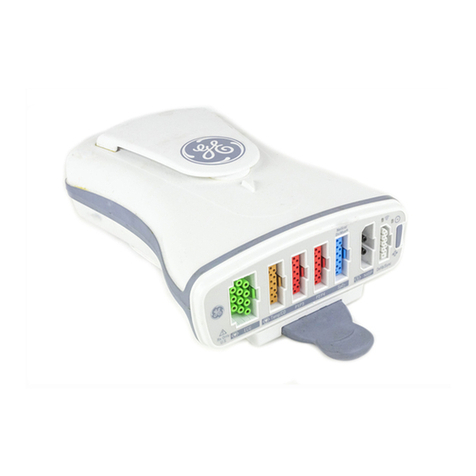
GE ApexPro TT User manual

GE Healthcare
ApexPro™
English
2028341-019 (cd)
2028340-042A (paper)
© 2008 General Electric Company.
All rights reserved.
ApexPro™ Antenna Infrastructure, Transmitter,
and Receiver
Technical Manual

T-2 ApexPro™ 2001989-351A
15 October 2008
NOTE
Due to continuing product innovation, specifications in this manual are subject to change without notice.
NOTE
The information in this manual only applies to ApexPro software version 3A and later, ApexPro CH software version 1A
and later, and the ApexPro, ApexPro CH, and CARESCAPE telemetry T14 transmitters hardware. It does not apply to
earlier software versions. Due to continuing product innovation, specifications in this manual are subject to change
without notice.
NOTE
For technical documentation purposes, the abbreviation GE is used for the legal entity name, GE Medical Systems
Information Technologies.
Listed below are GE Medical Systems Information Technologies trademarks. All other trademarks contained herein are the
property of their respective owners.
APEX, ApexPro, CARESCAPE and DINAMAP Pro are trademarks of GE Medical Systems Information Technologies
registered in the United States Patent and Trademark Office.
CIC is a trademark of GE Medical Systems Information Technologies.

2001989-351A ApexPro™ i
Contents
1 Introduction . . . . . . . . . . . . . . . . . . . . . . . . . . . . . . . . 1-1
Manual Information . . . . . . . . . . . . . . . . . . . . . . . . . . . . . . . . . . . . . . . . . . . . . 1-2
Revision history . . . . . . . . . . . . . . . . . . . . . . . . . . . . . . . . . . . . . . . . . . . . . 1-2
Purpose . . . . . . . . . . . . . . . . . . . . . . . . . . . . . . . . . . . . . . . . . . . . . . . . . . . 1-2
Intended audience . . . . . . . . . . . . . . . . . . . . . . . . . . . . . . . . . . . . . . . . . . . 1-2
Ordering manuals . . . . . . . . . . . . . . . . . . . . . . . . . . . . . . . . . . . . . . . . . . . 1-2
Conventions . . . . . . . . . . . . . . . . . . . . . . . . . . . . . . . . . . . . . . . . . . . . . . . . 1-2
Safety information . . . . . . . . . . . . . . . . . . . . . . . . . . . . . . . . . . . . . . . . . . . . . . 1-3
Intended use . . . . . . . . . . . . . . . . . . . . . . . . . . . . . . . . . . . . . . . . . . . . . . . 1-3
Responsibility of the manufacturer . . . . . . . . . . . . . . . . . . . . . . . . . . . . . . 1-3
Equipment symbols . . . . . . . . . . . . . . . . . . . . . . . . . . . . . . . . . . . . . . . . . . 1-3
Safety statements. . . . . . . . . . . . . . . . . . . . . . . . . . . . . . . . . . . . . . . . . . . . 1-5
Service information . . . . . . . . . . . . . . . . . . . . . . . . . . . . . . . . . . . . . . . . . . . . . 1-8
Service requirements . . . . . . . . . . . . . . . . . . . . . . . . . . . . . . . . . . . . . . . . . 1-8
Equipment identification . . . . . . . . . . . . . . . . . . . . . . . . . . . . . . . . . . . . . . 1-9
2 Equipment Overview . . . . . . . . . . . . . . . . . . . . . . . . . 2-1
System overview . . . . . . . . . . . . . . . . . . . . . . . . . . . . . . . . . . . . . . . . . . . . . . . 2-2
Overview . . . . . . . . . . . . . . . . . . . . . . . . . . . . . . . . . . . . . . . . . . . . . . . . . . 2-2
Power requirements . . . . . . . . . . . . . . . . . . . . . . . . . . . . . . . . . . . . . . . . . 2-3
Interface with ApexPro receiver subsystem . . . . . . . . . . . . . . . . . . . . . . . 2-3
Interface with multiple ApexPro receiver subsystems . . . . . . . . . . . . . . . . 2-3
Equipment . . . . . . . . . . . . . . . . . . . . . . . . . . . . . . . . . . . . . . . . . . . . . . . . . . . . 2-3
Unity Network . . . . . . . . . . . . . . . . . . . . . . . . . . . . . . . . . . . . . . . . . . . . . . 2-3
ApexPro antenna system . . . . . . . . . . . . . . . . . . . . . . . . . . . . . . . . . . . . . . 2-4
Enterprise Access antenna system . . . . . . . . . . . . . . . . . . . . . . . . . . . . . . 2-6
ApexPro and CARESCAPE transmitters . . . . . . . . . . . . . . . . . . . . . . . . . . 2-6
Transmitter controls, indicators and labels. . . . . . . . . . . . . . . . . . . . . . . . . 2-9
Transmitter interfaces. . . . . . . . . . . . . . . . . . . . . . . . . . . . . . . . . . . . . . . . 2-12
DINAMAP PRO series monitors . . . . . . . . . . . . . . . . . . . . . . . . . . . . . . . 2-14
SpO2 oximeter modules . . . . . . . . . . . . . . . . . . . . . . . . . . . . . . . . . . . . . 2-14
Apex oximeter. . . . . . . . . . . . . . . . . . . . . . . . . . . . . . . . . . . . . . . . . . . . . . 2-15
Interconnection cables . . . . . . . . . . . . . . . . . . . . . . . . . . . . . . . . . . . . . . . 2-16
ApexPro receiver system . . . . . . . . . . . . . . . . . . . . . . . . . . . . . . . . . . . . . 2-17
3 Installation and configuration . . . . . . . . . . . . . . . . . 3-1
Infrastructure installation . . . . . . . . . . . . . . . . . . . . . . . . . . . . . . . . . . . . . . . . 3-2
Overview . . . . . . . . . . . . . . . . . . . . . . . . . . . . . . . . . . . . . . . . . . . . . . . . . . 3-2
Install coaxial cable . . . . . . . . . . . . . . . . . . . . . . . . . . . . . . . . . . . . . . . . . . 3-2
Install antennas . . . . . . . . . . . . . . . . . . . . . . . . . . . . . . . . . . . . . . . . . . . . . 3-9

ii ApexPro™ 2001989-351A
Install antenna amplifiers . . . . . . . . . . . . . . . . . . . . . . . . . . . . . . . . . . . . . . 3-9
Install attenuators . . . . . . . . . . . . . . . . . . . . . . . . . . . . . . . . . . . . . . . . . . 3-11
Install power supplies and bias tees . . . . . . . . . . . . . . . . . . . . . . . . . . . . 3-11
Install notch/bandpass filters . . . . . . . . . . . . . . . . . . . . . . . . . . . . . . . . . . 3-12
ApexPro receiver installation. . . . . . . . . . . . . . . . . . . . . . . . . . . . . . . . . . . . 3-13
Mounting options . . . . . . . . . . . . . . . . . . . . . . . . . . . . . . . . . . . . . . . . . . . 3-13
Connections . . . . . . . . . . . . . . . . . . . . . . . . . . . . . . . . . . . . . . . . . . . . . . . 3-14
Setup antenna fields . . . . . . . . . . . . . . . . . . . . . . . . . . . . . . . . . . . . . . . . 3-15
Setup the receiver . . . . . . . . . . . . . . . . . . . . . . . . . . . . . . . . . . . . . . . . . . 3-17
Transmitter installation. . . . . . . . . . . . . . . . . . . . . . . . . . . . . . . . . . . . . . . . . 3-17
Programming the transmitter for use . . . . . . . . . . . . . . . . . . . . . . . . . . . . 3-18
Transmitter configuration. . . . . . . . . . . . . . . . . . . . . . . . . . . . . . . . . . . . . . . 3-18
Program code storage . . . . . . . . . . . . . . . . . . . . . . . . . . . . . . . . . . . . . . . 3-18
Error log . . . . . . . . . . . . . . . . . . . . . . . . . . . . . . . . . . . . . . . . . . . . . . . . . . 3-18
Parameters . . . . . . . . . . . . . . . . . . . . . . . . . . . . . . . . . . . . . . . . . . . . . . . 3-18
Manually view/program TTX. . . . . . . . . . . . . . . . . . . . . . . . . . . . . . . . . . . 3-19
4 Maintenance . . . . . . . . . . . . . . . . . . . . . . . . . . . . . . . . 4-1
ApexPro CH Telemetry Tune-Up . . . . . . . . . . . . . . . . . . . . . . . . . . . . . . . . . . 4-2
Introduction. . . . . . . . . . . . . . . . . . . . . . . . . . . . . . . . . . . . . . . . . . . . . . . . . 4-2
Visual inspection. . . . . . . . . . . . . . . . . . . . . . . . . . . . . . . . . . . . . . . . . . . . . . . 4-4
Inspect for damage . . . . . . . . . . . . . . . . . . . . . . . . . . . . . . . . . . . . . . . . . . 4-4
Verify transmitter features . . . . . . . . . . . . . . . . . . . . . . . . . . . . . . . . . . . . . 4-4
Verify labels . . . . . . . . . . . . . . . . . . . . . . . . . . . . . . . . . . . . . . . . . . . . . . . . 4-5
Cleaning . . . . . . . . . . . . . . . . . . . . . . . . . . . . . . . . . . . . . . . . . . . . . . . . . . . . . . 4-5
Cleaning products to avoid . . . . . . . . . . . . . . . . . . . . . . . . . . . . . . . . . . . . 4-6
Transmitter/device cleaning . . . . . . . . . . . . . . . . . . . . . . . . . . . . . . . . . . . . 4-6
ECG cable/leadwire cleaning . . . . . . . . . . . . . . . . . . . . . . . . . . . . . . . . . . . 4-8
Calibration . . . . . . . . . . . . . . . . . . . . . . . . . . . . . . . . . . . . . . . . . . . . . . . . . . . 4-10
Transmitter calibration . . . . . . . . . . . . . . . . . . . . . . . . . . . . . . . . . . . . . . . 4-10
Receiver calibration . . . . . . . . . . . . . . . . . . . . . . . . . . . . . . . . . . . . . . . . . 4-15
5 Troubleshooting . . . . . . . . . . . . . . . . . . . . . . . . . . . . 5-1
Troubleshooting tree 1 . . . . . . . . . . . . . . . . . . . . . . . . . . . . . . . . . . . . . . . . . . 5-2
Troubleshooting tree 2 . . . . . . . . . . . . . . . . . . . . . . . . . . . . . . . . . . . . . . . . . . 5-3
ApexPro transmitter troubleshooting tree . . . . . . . . . . . . . . . . . . . . . . . . . . 5-4
System troubleshooting . . . . . . . . . . . . . . . . . . . . . . . . . . . . . . . . . . . . . . . . . 5-5
RF drop-out determination . . . . . . . . . . . . . . . . . . . . . . . . . . . . . . . . . . . . . 5-5
Yellow drop-out condition . . . . . . . . . . . . . . . . . . . . . . . . . . . . . . . . . . . . . . 5-5
Quick antenna system checks . . . . . . . . . . . . . . . . . . . . . . . . . . . . . . . . . . 5-7

2001989-351A ApexPro™ iii
Antenna system troubleshooting . . . . . . . . . . . . . . . . . . . . . . . . . . . . . . . . . 5-7
ApexPro transmitter carrier impairment measurement procedure. . . . . . . 5-9
Rationale for test . . . . . . . . . . . . . . . . . . . . . . . . . . . . . . . . . . . . . . . . . . . . 5-9
Equipment needed . . . . . . . . . . . . . . . . . . . . . . . . . . . . . . . . . . . . . . . . . 5-10
Rohde & Schwarz FSH3 test procedure . . . . . . . . . . . . . . . . . . . . . . . . . 5-10
Receiver subsystem troubleshooting . . . . . . . . . . . . . . . . . . . . . . . . . . . . . 5-13
Receiver Subsystem LED status chart . . . . . . . . . . . . . . . . . . . . . . . . . . 5-13
General fault isolation. . . . . . . . . . . . . . . . . . . . . . . . . . . . . . . . . . . . . . . . 5-14
Verify connectivity. . . . . . . . . . . . . . . . . . . . . . . . . . . . . . . . . . . . . . . . . . . 5-15
AC line voltage test. . . . . . . . . . . . . . . . . . . . . . . . . . . . . . . . . . . . . . . . . . 5-18
Event logs. . . . . . . . . . . . . . . . . . . . . . . . . . . . . . . . . . . . . . . . . . . . . . . . . 5-19
Before calling service . . . . . . . . . . . . . . . . . . . . . . . . . . . . . . . . . . . . . . . . . . 5-21
System dropout . . . . . . . . . . . . . . . . . . . . . . . . . . . . . . . . . . . . . . . . . . . . 5-21
Transmitter . . . . . . . . . . . . . . . . . . . . . . . . . . . . . . . . . . . . . . . . . . . . . . . . 5-21
Apex oximeter and Nonin Xpod oximeter . . . . . . . . . . . . . . . . . . . . . . . . 5-23
Apex oximeter short battery life . . . . . . . . . . . . . . . . . . . . . . . . . . . . . . . . 5-23
Power shutdown during leads fail . . . . . . . . . . . . . . . . . . . . . . . . . . . . . . . . 5-24
ApexPro . . . . . . . . . . . . . . . . . . . . . . . . . . . . . . . . . . . . . . . . . . . . . . . . . . 5-24
ApexPro CH and T14 . . . . . . . . . . . . . . . . . . . . . . . . . . . . . . . . . . . . . . . 5-24
6 Replaceable parts . . . . . . . . . . . . . . . . . . . . . . . . . . . 6-1
Mounting hardware and labels . . . . . . . . . . . . . . . . . . . . . . . . . . . . . . . . . . . 6-2
Optional antenna mounting kits . . . . . . . . . . . . . . . . . . . . . . . . . . . . . . . . . . 6-3
Power supply . . . . . . . . . . . . . . . . . . . . . . . . . . . . . . . . . . . . . . . . . . . . . . . . . 6-4
Bias tee . . . . . . . . . . . . . . . . . . . . . . . . . . . . . . . . . . . . . . . . . . . . . . . . . . . . . . 6-4
Bias tee & power supply mounting kit . . . . . . . . . . . . . . . . . . . . . . . . . . . . . 6-5
Antenna amplifier . . . . . . . . . . . . . . . . . . . . . . . . . . . . . . . . . . . . . . . . . . . . . . 6-5
Coaxial cabling - RG-6 and RG-11 . . . . . . . . . . . . . . . . . . . . . . . . . . . . . . . . . 6-6
Connectors . . . . . . . . . . . . . . . . . . . . . . . . . . . . . . . . . . . . . . . . . . . . . . . . . . . 6-6
Adapters . . . . . . . . . . . . . . . . . . . . . . . . . . . . . . . . . . . . . . . . . . . . . . . . . . . . . 6-8
Block and terminator. . . . . . . . . . . . . . . . . . . . . . . . . . . . . . . . . . . . . . . . . . . . 6-9
75-Ohm terminator . . . . . . . . . . . . . . . . . . . . . . . . . . . . . . . . . . . . . . . . . . 6-9
DC-power block . . . . . . . . . . . . . . . . . . . . . . . . . . . . . . . . . . . . . . . . . . . . . 6-9
Splitters/combiners . . . . . . . . . . . . . . . . . . . . . . . . . . . . . . . . . . . . . . . . . . . . 6-9
DC passing attenuators . . . . . . . . . . . . . . . . . . . . . . . . . . . . . . . . . . . . . . . . 6-10
Notch filters . . . . . . . . . . . . . . . . . . . . . . . . . . . . . . . . . . . . . . . . . . . . . . . . . . 6-10

iv ApexPro™ 2001989-351A
Bandpass filters. . . . . . . . . . . . . . . . . . . . . . . . . . . . . . . . . . . . . . . . . . . . . . . 6-14
ApexPro bandpass filter 608-614 MHz . . . . . . . . . . . . . . . . . . . . . . . . . . 6-14
Cavity bandpass filter 608-614 MHz . . . . . . . . . . . . . . . . . . . . . . . . . . . . 6-16
International bandpass filter 433.05-434.75 MHz . . . . . . . . . . . . . . . . . . 6-18
International bandpass filter 458.5-459.1 MHz . . . . . . . . . . . . . . . . . . . . 6-19
Power cords . . . . . . . . . . . . . . . . . . . . . . . . . . . . . . . . . . . . . . . . . . . . . . . . . 6-19
Ordering parts . . . . . . . . . . . . . . . . . . . . . . . . . . . . . . . . . . . . . . . . . . . . . . . . 6-20
Field replaceable units . . . . . . . . . . . . . . . . . . . . . . . . . . . . . . . . . . . . . . . 6-20
Label kits . . . . . . . . . . . . . . . . . . . . . . . . . . . . . . . . . . . . . . . . . . . . . . . . . 6-21
Transmitters . . . . . . . . . . . . . . . . . . . . . . . . . . . . . . . . . . . . . . . . . . . . . . . . . 6-22
Interconnect cables . . . . . . . . . . . . . . . . . . . . . . . . . . . . . . . . . . . . . . . . . . . 6-22
Labels . . . . . . . . . . . . . . . . . . . . . . . . . . . . . . . . . . . . . . . . . . . . . . . . . . . . . . . 6-22
ApexPro . . . . . . . . . . . . . . . . . . . . . . . . . . . . . . . . . . . . . . . . . . . . . . . . . . 6-22
ApexPro CH . . . . . . . . . . . . . . . . . . . . . . . . . . . . . . . . . . . . . . . . . . . . . . . 6-23
T14 . . . . . . . . . . . . . . . . . . . . . . . . . . . . . . . . . . . . . . . . . . . . . . . . . . . . . 6-23
Optional components and accessories . . . . . . . . . . . . . . . . . . . . . . . . . . . 6-23
ApexPro CH transmitter parts list . . . . . . . . . . . . . . . . . . . . . . . . . . . . . . . . 6-23
T14 transmitter parts list . . . . . . . . . . . . . . . . . . . . . . . . . . . . . . . . . . . . . . . 6-24
Receiver subsystem disassembly guidelines. . . . . . . . . . . . . . . . . . . . . . . 6-24
General . . . . . . . . . . . . . . . . . . . . . . . . . . . . . . . . . . . . . . . . . . . . . . . . . . 6-24
Replace the fuse . . . . . . . . . . . . . . . . . . . . . . . . . . . . . . . . . . . . . . . . . . . 6-25
Open the unit . . . . . . . . . . . . . . . . . . . . . . . . . . . . . . . . . . . . . . . . . . . . . . 6-25
Remove a quad receiver module . . . . . . . . . . . . . . . . . . . . . . . . . . . . . . . 6-26
Add a quad receiver module . . . . . . . . . . . . . . . . . . . . . . . . . . . . . . . . . . 6-26
Remove/replace the power supply assembly . . . . . . . . . . . . . . . . . . . . . 6-27
Remove/replace receiver subsystem pcb (backplane) . . . . . . . . . . . . . . 6-27
Close and reconnect unit . . . . . . . . . . . . . . . . . . . . . . . . . . . . . . . . . . . . . 6-28
Receiver system drawings . . . . . . . . . . . . . . . . . . . . . . . . . . . . . . . . . . . . . . 6-29
Receiver assembly . . . . . . . . . . . . . . . . . . . . . . . . . . . . . . . . . . . . . . . . . 6-29
Quad receiver module . . . . . . . . . . . . . . . . . . . . . . . . . . . . . . . . . . . . . . . 6-30
7 Checkout . . . . . . . . . . . . . . . . . . . . . . . . . . . . . . . . . . 7-1
Antenna checkout . . . . . . . . . . . . . . . . . . . . . . . . . . . . . . . . . . . . . . . . . . . . . . 7-2
Procedure . . . . . . . . . . . . . . . . . . . . . . . . . . . . . . . . . . . . . . . . . . . . . . . . . 7-2
Infrastructure equipment checkout . . . . . . . . . . . . . . . . . . . . . . . . . . . . . . . . 7-2
Procedure . . . . . . . . . . . . . . . . . . . . . . . . . . . . . . . . . . . . . . . . . . . . . . . . . 7-2
Receiver subsystem checkout. . . . . . . . . . . . . . . . . . . . . . . . . . . . . . . . . . . . 7-2
Checkout procedure . . . . . . . . . . . . . . . . . . . . . . . . . . . . . . . . . . . . . . . . . 7-2

2001989-351A ApexPro™ v
Additional system tests. . . . . . . . . . . . . . . . . . . . . . . . . . . . . . . . . . . . . . . . 7-3
Transmitter checkout . . . . . . . . . . . . . . . . . . . . . . . . . . . . . . . . . . . . . . . . . . 7-11
Checkout procedure . . . . . . . . . . . . . . . . . . . . . . . . . . . . . . . . . . . . . . . . 7-11
Additional system tests. . . . . . . . . . . . . . . . . . . . . . . . . . . . . . . . . . . . . . . 7-12
Oximeter operational tests . . . . . . . . . . . . . . . . . . . . . . . . . . . . . . . . . . . . . . 7-19
Apex oximeter . . . . . . . . . . . . . . . . . . . . . . . . . . . . . . . . . . . . . . . . . . . . . 7-19
Nonin Xpod . . . . . . . . . . . . . . . . . . . . . . . . . . . . . . . . . . . . . . . . . . . . . . . 7-20
Accutracker DX NIBP operational tests. . . . . . . . . . . . . . . . . . . . . . . . . . . . 7-20
Display . . . . . . . . . . . . . . . . . . . . . . . . . . . . . . . . . . . . . . . . . . . . . . . . . . . 7-21
Pressure calibration check . . . . . . . . . . . . . . . . . . . . . . . . . . . . . . . . . . . 7-21
Over-pressure release check . . . . . . . . . . . . . . . . . . . . . . . . . . . . . . . . . 7-22
Hardware time-out and system leak check . . . . . . . . . . . . . . . . . . . . . . . 7-22
Communication test . . . . . . . . . . . . . . . . . . . . . . . . . . . . . . . . . . . . . . . . . 7-23
Repair log . . . . . . . . . . . . . . . . . . . . . . . . . . . . . . . . . . . . . . . . . . . . . . . . . . . 7-23
A Technical specifications . . . . . . . . . . . . . . . . . . . . . .A-1
ApexPro and ApexPro CH transmitter. . . . . . . . . . . . . . . . . . . . . . . . . . . . . A-2
Performance specifications . . . . . . . . . . . . . . . . . . . . . . . . . . . . . . . . . . . A-2
Environmental specifications . . . . . . . . . . . . . . . . . . . . . . . . . . . . . . . . . . A-3
Device specifications . . . . . . . . . . . . . . . . . . . . . . . . . . . . . . . . . . . . . . . . . A-3
Analog/digital . . . . . . . . . . . . . . . . . . . . . . . . . . . . . . . . . . . . . . . . . . . . . . . A-4
Physical specifications . . . . . . . . . . . . . . . . . . . . . . . . . . . . . . . . . . . . . . . .A-4
Certifications . . . . . . . . . . . . . . . . . . . . . . . . . . . . . . . . . . . . . . . . . . . . . . . A-5
T14 transmitter. . . . . . . . . . . . . . . . . . . . . . . . . . . . . . . . . . . . . . . . . . . . . . . . A-5
Performance specifications . . . . . . . . . . . . . . . . . . . . . . . . . . . . . . . . . . . A-5
Environmental specifications . . . . . . . . . . . . . . . . . . . . . . . . . . . . . . . . . . A-6
Device specifications . . . . . . . . . . . . . . . . . . . . . . . . . . . . . . . . . . . . . . . . . A-6
Physical specifications . . . . . . . . . . . . . . . . . . . . . . . . . . . . . . . . . . . . . . . .A-7
FCC compliance information . . . . . . . . . . . . . . . . . . . . . . . . . . . . . . . . . . . A-7
Certifications . . . . . . . . . . . . . . . . . . . . . . . . . . . . . . . . . . . . . . . . . . . . . . . A-7
Apex oximeter . . . . . . . . . . . . . . . . . . . . . . . . . . . . . . . . . . . . . . . . . . . . . . . . A-8
Performance specifications . . . . . . . . . . . . . . . . . . . . . . . . . . . . . . . . . . . . A-8
Physical specifications . . . . . . . . . . . . . . . . . . . . . . . . . . . . . . . . . . . . . . . .A-8
Certification . . . . . . . . . . . . . . . . . . . . . . . . . . . . . . . . . . . . . . . . . . . . . . . . A-8
Nonin Xpod oximeter. . . . . . . . . . . . . . . . . . . . . . . . . . . . . . . . . . . . . . . . . . . A-9
Performance specifications . . . . . . . . . . . . . . . . . . . . . . . . . . . . . . . . . . . . A-9
Physical specifications . . . . . . . . . . . . . . . . . . . . . . . . . . . . . . . . . . . . . . . .A-9
Certification . . . . . . . . . . . . . . . . . . . . . . . . . . . . . . . . . . . . . . . . . . . . . . . . A-9
Accutracker DX noninvasive blood pressure monitor. . . . . . . . . . . . . . . . A-9
Performance specifications . . . . . . . . . . . . . . . . . . . . . . . . . . . . . . . . . . . . A-9
Environmental specifications . . . . . . . . . . . . . . . . . . . . . . . . . . . . . . . . . . A-11
Physical specifications . . . . . . . . . . . . . . . . . . . . . . . . . . . . . . . . . . . . . . .A-11
Certification . . . . . . . . . . . . . . . . . . . . . . . . . . . . . . . . . . . . . . . . . . . . . . . A-11
vi ApexPro™ 2001989-351A
ApexPro receiver . . . . . . . . . . . . . . . . . . . . . . . . . . . . . . . . . . . . . . . . . . . . . A-12
Performance specifications . . . . . . . . . . . . . . . . . . . . . . . . . . . . . . . . . . A-12
Environmental specifications . . . . . . . . . . . . . . . . . . . . . . . . . . . . . . . . . . A-12
Physical specifications . . . . . . . . . . . . . . . . . . . . . . . . . . . . . . . . . . . . . . .A-13
Certification . . . . . . . . . . . . . . . . . . . . . . . . . . . . . . . . . . . . . . . . . . . . . . . A-13
Antenna specifications . . . . . . . . . . . . . . . . . . . . . . . . . . . . . . . . . . . . . . . . A-13
Performance specifications . . . . . . . . . . . . . . . . . . . . . . . . . . . . . . . . . . . A-13
Environmental specifications . . . . . . . . . . . . . . . . . . . . . . . . . . . . . . . . . A-14
Physical specifications . . . . . . . . . . . . . . . . . . . . . . . . . . . . . . . . . . . . . . .A-14
Warranty information . . . . . . . . . . . . . . . . . . . . . . . . . . . . . . . . . . . . . . . . A-14
Power supply specifications . . . . . . . . . . . . . . . . . . . . . . . . . . . . . . . . . . . A-14
Power requirements . . . . . . . . . . . . . . . . . . . . . . . . . . . . . . . . . . . . . . . . A-14
Environmental specifications . . . . . . . . . . . . . . . . . . . . . . . . . . . . . . . . . A-14
Device specifications . . . . . . . . . . . . . . . . . . . . . . . . . . . . . . . . . . . . . . . . A-15
Bias tee specifications . . . . . . . . . . . . . . . . . . . . . . . . . . . . . . . . . . . . . . . . A-15
Environmental specifications . . . . . . . . . . . . . . . . . . . . . . . . . . . . . . . . . . A-15
Device specifications . . . . . . . . . . . . . . . . . . . . . . . . . . . . . . . . . . . . . . . . A-15
Bias tee & power supply mounting kit specifications . . . . . . . . . . . . . . . A-16
Physical specifications . . . . . . . . . . . . . . . . . . . . . . . . . . . . . . . . . . . . . . .A-16
Antenna amplifier specifications . . . . . . . . . . . . . . . . . . . . . . . . . . . . . . . . A-16
Environmental specifications . . . . . . . . . . . . . . . . . . . . . . . . . . . . . . . . . . A-16
Device specifications . . . . . . . . . . . . . . . . . . . . . . . . . . . . . . . . . . . . . . . . A-16
B Electromagnetic compatibility . . . . . . . . . . . . . . . . .B-1
ApexPro and CARESCAPE transmitters . . . . . . . . . . . . . . . . . . . . . . . . . . . B-2
Electromagnetic compatibility (EMC) . . . . . . . . . . . . . . . . . . . . . . . . . . . . . B-2
Guidance and manufacturer’s declaration – electromagnetic emissions . B-2
Guidance and manufacturer’s declaration – electromagnetic immunity . . B-3
Recommended separation distances . . . . . . . . . . . . . . . . . . . . . . . . . . . . B-5
Compliant cables and accessories . . . . . . . . . . . . . . . . . . . . . . . . . . . . . . B-6
ApexPro receiver . . . . . . . . . . . . . . . . . . . . . . . . . . . . . . . . . . . . . . . . . . . . . . B-7
Electromagnetic compatibility (EMC) . . . . . . . . . . . . . . . . . . . . . . . . . . . . . B-7
Guidance and manufacturer’s declaration . . . . . . . . . . . . . . . . . . . . . . . . B-7
Recommended separation distances . . . . . . . . . . . . . . . . . . . . . . . . . . . B-10
Compliant cables and accessories . . . . . . . . . . . . . . . . . . . . . . . . . . . . . B-11

2001989-351A ApexPro™ vii

viii ApexPro™ 2001989-351A

2001989-351A ApexPro™ 1-1
1
Introduction

1-2 ApexPro™ 2001989-351A
Introduction
Manual Information
Revision history
Each page of this manual has the document part number and revision letter at the
bottom of the page. The revision letter identifies the document’s update level. The
revision history of this document is summarized below.
Purpose
This manual provides technical information for maintaining the ApexPro, ApexPro
CH and CARESCAPE T14 transmitters, ApexPro receiver subsystem, ApexPro
antenna infrastructure equipment and GE equipment that connects to the transmitter.
Intended audience
Users of this manual are expected to have a background in electronics, including
analog and digital circuitry, RF, and microprocessor architectures. It is intended for
service representatives and technical personnel who maintain, troubleshoot or repair
this equipment.
Ordering manuals
A paper copy of this manual will be provided upon request. Contact your local GE
representative and request the part number on the first page of the manual.
Conventions
Revision Comment
A Initial release
Style Definition
bold Indicates hardware items such as keys, labels, or text entered by the
user.
bold italic Indicates software terms such as menu items or screen text.
+Indicates keyboard keys to select simultaneously.
> Indicates menu options to select consecutively.

Introduction
2001989-351A ApexPro™ 1-3
Safety information
Intended use
The ApexPro Telemetry System is intended for use under the direct supervision of a
licensed healthcare practitioner. The system is designed to acquire and monitor
physiological data for ambulating adult and pediatric patients within a defined
coverage area. The system processes this physiological data to detect various ECG
arrhythmia events and select physiological parameter limit violations.
The ApexPro Telemetry System is intended to be installed in the hospital or clinical
environment in order to provide clinicians with patient physiological data, while
allowing for patient mobility. These systems are typically deployed in sub acute care
areas in hospitals or clinical sites where patient mobility can enhance the
effectiveness of the medical procedures administered.
The physiological parameters monitored include ECG, non-invasive blood pressure,
non-invasive temperature and SpO2. The ApexPro Telemetry System is intended to
provide ECG data via Ethernet to the computer platform for processing. The ApexPro
is also intended to provide physiologic data over the Unity network to clinical
information systems for display.
Responsibility of the manufacturer
GE is responsible for the effects of safety, reliability, and performance only if:
assembly operations, extensions, readjustments, modifications, or repairs are
carried out by persons authorized by GE;
the electrical installation of the relevant room complies with the requirements of
the appropriate regulations; and
the device is used in accordance with the instructions for use.
Equipment symbols
NOTE
Some symbols may not appear on all equipment.
ATTENTION: Consult accompanying documents.
Non-ionizing electromagnetic radiation: To indicate elevated, potentially dangerous, levels of non-ionizing radiation. Note -
In case of application in a warning sign the rules according to ISO 3864-1 shall be adhered to.
IEC 60878 note: See safety sign ISO 7010 - W005 “Warning, non-ionizing radiation”.

1-4 ApexPro™ 2001989-351A
Introduction
Type CF applied part: Isolated (floating) applied part suitable for intentional external and internal application to the patient
including direct cardiac application. “Paddles” outside the box indicate the applied part is defibrillator proof.
[Medical Standard Definition:] F-type applied part (floating/isolated) complying with the specified requirements of IEC
60601-1/UL 60601-1/CSA 601.1 Medical Standards to provide a higher degree of protection against electric shock than
that provided by type BF applied parts.
NOTE
The rating of protection against electric shock (indicated by symbol for CF) is achieved only when used with patient
applied parts recommended by GE.
TYPE B APPLIED PART: Non-isolated applied part suitable for intentional external and internal application to the patient
excluding direct cardiac application.
[Medical Standard Definition:] Applied part complying with the specified requirements of IEC 60601-1/UL 60601-1/CSA
601.1 Medical Standards to provide protection against electric shock, particularly regarding allowable leakage current.
R&TTE equipment class 2 identifier: An alert sign, indicating that transmitting radio equipment operates in non-
harmonized frequency bands and can cause interference.
Equipotential
DC In/RF Out or DC Out/RF In
DC In or RF In
For indoor use only.
Power supply cable configuration.
+ = Power
– = Return
4P41
Medical Equipment
With respect to electric shock, fire and mechanical hazards only in accordance with UL 60601-1, and CAN/CSA C22.2 NO.
601.1 and if applicable, IEC 60601-2-27, IEC 60601-2-30, and IEC 60601-2-49.
CE mark CE-0459 indicating conformity with the provisions of the Council Directive 93/42/EEC concerning medical
devices, and fulfills the essential requirements of Annex I of this directive.
Interface Connector(s)
INTFC.

Introduction
2001989-351A ApexPro™ 1-5
Safety statements
Dangers
Danger statements identify an imminent hazard which, if not avoided, will result in
death or serious injury. No danger statements apply to this product.
Warnings
Warning statements identify a potential hazard or unsafe practice which, if not
avoided, could result in death or serious injury. The following warnings apply to this
product.
WARNING
BEFORE USE —Periodically, and whenever the integrity of the
device is in doubt, test all functions.
WARNING
EXPLOSION HAZARD —Do not use this equipment in the
presence of flammable anesthetics, vapors or liquids.
Complies with IPX3 standards for water ingress
Complies with IPX7 standards for water ingress
This symbol indicates that the waste of electrical and electronic equipment must not be disposed as unsorted municipal
waste and must be collected separately. Please contact an authorized representative of the manufacturer for information
concerning the decommissioning of your equipment.
This symbol indicates the date of manufacture of this device. The first 4 digits identify the year and the last 2 digits identify
the month.
Manufacturer name and address.
European authorized representative.
2005-08

1-6 ApexPro™ 2001989-351A
Introduction
WARNING
FALSE CALLS—False low heart rate indicators or false asystole
calls may result with certain pacemakers because of electrical
overshoot.
WARNING
INTERFACING WITH OTHER EQUIPMENT —Contact GE for
information before connecting any devices to the equipment that are
not recommended in this manual.
WARNING
LOSS OF DATA — Notify the affected users relying upon this data
flow before shutting down the ApexPro™ antenna infrastructure
components for any reason.
WARNING
MONITORING PACEMAKER PATIENTS —Monitoring of
pacemaker patients can only occur with the pace program activated.
WARNING
PACEMAKER SPIKE —An artificial pacemaker spike is displayed
in place of the actual pacemaker spike. All pacemaker spikes appear
uniform. Do not diagnostically interpret pacemaker spike size and
shape.
WARNING
PATIENT HAZARD —A pacemaker pulse can be counted as a QRS
during asystole in either pace mode. Keep pacemaker patients under
close observation.
WARNING
RATE METERS—Keep pacemaker patients under close
observation. Rate meters may continue to count the pacemaker rate
during cardiac arrest and some arrhythmias. Therefore, do not rely
entirely on rate meter alarms.
Cautions
Caution statements identify a potential hazard or unsafe practice which, if not
avoided, could result in minor personal injury or product/property damage. The
following cautions apply to this product.

Introduction
2001989-351A ApexPro™ 1-7
CAUTION
ACCESSORIES (SUPPLIES) —To ensure patient safety, use only
parts and accessories manufactured or recommended by GE.
Parts and accessories used must meet the requirements of the
applicable IEC 60601 series safety standards, and/or the system
configuration must meet the requirements of the IEC 60601 medical
electrical systems standard.
CAUTION
ACCESSORIES (EQUIPMENT) —The use of accessory equipment
not complying with the equivalent safety requirements of this
equipment may lead to a reduced level of safety of the resulting
system. Consideration relating to the choice shall include:
use of the accessory in the patient environment; and
evidence that the safety certification of the accessory has been
performed in accordance to the appropriate IEC 60601-1 and/or
IEC 60601 harmonized national standard.
CAUTION
FDA POSTMARKET SAFETY ALERT—The United States FDA
Center for Devices and Radiological Health issued a safety bulletin
October 14, 1998. This bulletin states “that minute ventilation rate-
adaptive implantable pacemakers can occasionally interact with
certain cardiac monitoring and diagnostic equipment, causing the
pacemakers to pace at their maximum programmed rate.”
The FDA further recommends precautions to take into
consideration for patients with these types of pacemakers. These
precautions include disabling the rate responsive mode and
enabling an alternate pace mode. For more information contact:
Office of Surveillance and Biometrics, CDRH, FDA
1350 Piccard Drive, Mail Stop HFZ-510
Rockville, MD 20850
U.S.A.
CAUTION
POWER REQUIREMENTS —If the installation of the equipment,
in the USA, uses 240V rather than 120V, the source must be a
center-tapped, 240V, single-phase circuit.
CAUTION
RESTRICTED SALE —Federal law restricts this device to be sold
by or on the order of a physician.

1-8 ApexPro™ 2001989-351A
Introduction
CAUTION
SUPERVISED USE —This system is intended for use under the
direct supervision of a licensed health care practitioner.
Notes
Note statements provide application tips or other useful information to assure that you
get the most from your equipment. The following notes apply to this product.
NOTE
ECG monitoring with patients on non-invasive transcutaneous pacemakers may
not be possible due to large amounts of energy produced by these devices.
Monitoring ECG with an external device may be needed.
NOTE
This device is not intended for home use.
NOTE
Patient environment is any volume in which intentional or unintentional contact
can occur between patient and parts of the system or between patient and other
persons touching parts of the system. (IEC 60601-1-1)
Service information
Service requirements
Follow the service requirements listed below.
Refer equipment servicing to GE authorized service personnel only.
Any unauthorized attempt to repair equipment under warranty voids that
warranty.
It is the user’s responsibility to report the need for service to GE or to one of their
authorized agents.
Failure on the part of the responsible individual, hospital, or institution using this
equipment to implement a satisfactory maintenance schedule may cause undue
equipment failure and possible health hazards.
Regular maintenance, irrespective of usage, is essential to ensure that the
equipment will always be functional when required.

Introduction
2001989-351A ApexPro™ 1-9
Equipment identification
Every GE device has a unique serial number for identification. A sample of the
information found on a serial number label is shown below.
Description
Aproduct code1
1
The product code is: TT for ApexPro transmitter, domestic; AM for
ApexPro transmitter, international; T9 for ApexPro CH transmitter;
SE3 for the CARESCAPE Telemetry T14 transmitter; RTS for US
(560-614 MHz) ApexPro receiver subsystem; and RAV for
international (420-474 MHz) ApexPro receiver subsystem.
B year manufactured
C fiscal week manufactured
D production sequence number
E manufacturing site
F miscellaneous characteristic
### ## ## #### # #
ABCDEF

1-10 ApexPro™ 2001989-351A
Introduction
This manual suits for next models
8
Table of contents
Other GE Medical Equipment manuals

GE
GE Optima IGS 320 User manual

GE
GE MAC 3500 User manual

GE
GE Marquette 418793-001 User manual

GE
GE Solar 7000 User manual

GE
GE MAC 2000 User manual

GE
GE Dash 2500 User manual

GE
GE Vivid S70 User manual

GE
GE Healthcare eXplore Locus SP User manual

GE
GE CARESCAPE Monitor B850 User manual

GE
GE LOGIQ 7 Pro User manual

GE
GE Vivid 4 BT03 RFI User manual

GE
GE Vivid E9 User manual

GE
GE Invenia ABUS User manual

GE
GE Voluson E Series User manual

GE
GE Vivid S60 User manual

GE
GE Vivid E9 User manual

GE
GE PANDA User manual

GE
GE CareScape V100 User manual

GE
GE Voluson 730Pro User manual

GE
GE Giraffe OmniBed Carestation CS1 User manual