2
NOTE: To avoid overloading this power
supply with LED modules, please refer
to the specic module loading guides.
Power Supply Installation
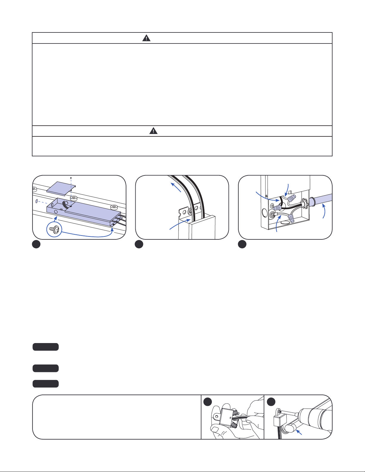
Connect the supply wire that is attached
to your LED system to the red (+) and
black (-) output wires of the LED driver as
outlined in the “Electrical Connections”
section of your LED system’s Installation
Instructions.
NOTE: Three 96 watt output banks
per power supply. Do not interconnect
output terminations.
2
Remove the junction box cover and carefully
remove knockout for AC line input wires.
Install appropriate electrical ttings in the
knockout holes for wire protection. Securely
mount the power supply with the base
in contact with the mounting surface in
accordance with the power supply spacing
requirements described in the Warning
Section. If used in a wet location, the power
supply and electrical connections shall be
protected from weather by a suitable rain
enclosure, and not subject to saturation with
water or other liquids. If not protected from
the weather, the output DC connections with
LED module must also be protected by a
weather box or with electrical grade silicone.
Please, refer to the LED module install
instructions for more details.
Connect the AC line to the black (line)
and white (neutral) input wires of the
power supply and connect the branch
circuit ground to the green wire with
a yellow stripe (ground) wire using
appropriately sized twist-on wire
connectors.
1
White (neutral)
Black
(line)
Green with yellow stripe (ground)
AC line
3
To LED system
Output wires
WARNING/AVERTISSEMENT
RISK OF ELECTRIC SHOCK
• Disconnect power at fuse box or circuit breaker before servicing
or installing product.
• Properly ground Tetra®power supply.
RISK OF FIRE
• Two or more adjacent LED drivers or LED power supplies shall
not be mounted closer than 1 in. end to end or 4 in. side to side
unless temperature tested for the application..
• Use only approved wire for input/output connection. Minimum
size 18 AWG (0.82 mm2).
• Follow all local codes.
• Application considerations potentially requiring additional
spacing include high ambient temperature seen by the
power supply, poor contact with a heat dissipating material,
inadequate ventilation, or direct exposure to sun.
RISQUES DE DÉCHARGES ÉLECTRIQUES
• Coupez l’alimentation électrique à la boîte de fusibles ou au disjoncteur avant
l’entretien ou l’installation du produit.
• Assurez-vous de correctement mettre à terre le bloc d’alimentation Tetra®.
RISQUES D’INCENDIE
• Deux ou plusieurs blocs d’alimentation adjacents ne doivent pas être
installés à moins de 1 po de bout en bout ou de 4 po d’un côté à l’autre,
sauf si des essais de température pour l’application ont été effectués.
• N’utilisez que des ls approuvés pour les entrées/sorties de connexion.
Taille minimum 18 AWG (0.82 mm2).
• Respectez tous les codes locaux.
• Certaines applications pourraient requérir un espacement additionnel, p.
ex. une température ambiante élevée autour du bloc d’alimentation, un
mauvais contact avec une matière dissipatrice de chaleur, une ventilation
inadéquate ou une exposition directe au soleil.
CAUTION/ATTENTION
RISK OF INJURY
• While performing installations described, gloves, safety
glasses or goggles should be worn.
RISQUES DE BLESSURE
• Lors de l’exécution des installations décrites, des gants, des lunettes de
sécurité ou des lunettes de protection doivent être portées.
FOR UL ONLY
NOTE: For CSA approval, a disconnect/toggle switch of appropriate rating needs to be placed within 29.5 ft. (9 m) of
primary side of the power supply. The minimum rating of the switch must be either 120 or 220 Volts AC. The switch
must also support twice the amount of input current.
FOR UL ONLY
NOTE: When installing power supply, connect to the appropriate sized building breaker or disconnect device for line
and neutral connections, in accordance with local, state or country regulations.
FOR UL ONLY
NOTE: The grounding and bonding of the power supply and overall sign shall be done in accordance with National
Electric Code (NEC) Article 600.
OPTIONAL
A Weather Box (GEXNWB2) may be used to house and seal Class 2
connections.
A) Insert wire connectors into weather box. Fill with electrical grade
silicone and close box.
B) Secure the weather box using a #6 or #8 (M2 or M3) screw.
Weather box
can be painted
A B
Light engine


