manuals.online logo
Brands
  1. Home
  2. •
  3. Brands
  4. •
  5. GE
  6. •
  7. Power Supply
  8. •
  9. GE Current Tetra GEPS12-25U-EU Manual

GE Current Tetra GEPS12-25U-EU Manual

1
Volt
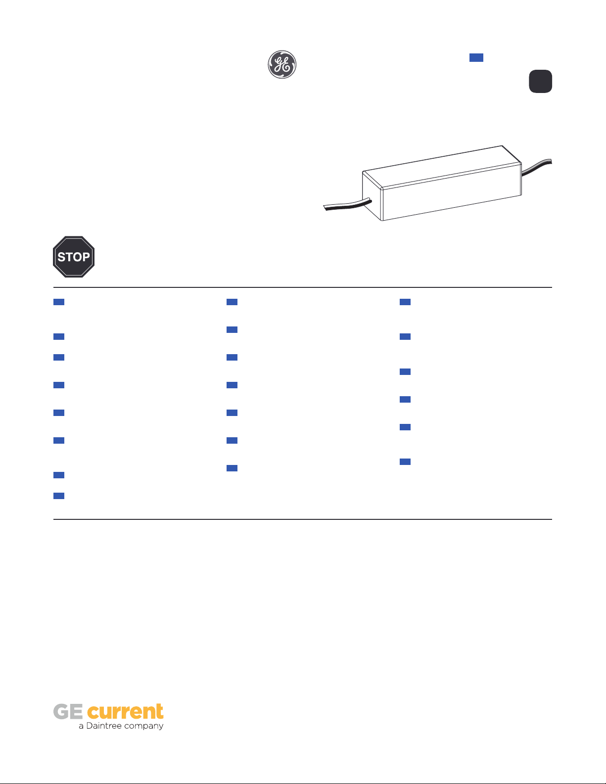
Power Supply Features
®LED Systems
Power Supply
GEPS12-25U-EU
• Supports all 12 VDC Tetra Products
• SELV Compliant
• 220-240 VAC Input
Save These Instructions
Use only in the manner intended by the manufacturer.
If you have any questions, contact the manufacturer.
12
Tetra
( VAC input / VDC output / W)220-240 12 25
EN Instruction Guide
BEFORE YOU BEGIN
Read these instructions completely and carefully.
For the latest North American install guides for your product go to: https://products.currentbyge.com/led-signage-lighting
For the latest European install guides for your product go to: https://products.currentbyge.com/eu
BG Българската версия на инструкциите за инсталаця
и информация за безопасност могат да бъдат
намерени на следния адрес: https://products.
currentbyge.com/eu
CS Návod k montáží a bezpečnostní informace v češtině
najdete zde: https://products.currentbyge.com/eu
DA Den danske version af installationsvejledningen
og sikkerhedsoplysninger kan findes på følgende
placering: https://products.currentbyge.com/eu
DE Die deutsche Version der Installationsanleitung und
Sicherheitsinformationen finden Sie in folgendem
Verzeic: https://products.currentbyge.com/eu
EL Μπορείτε να βρείτε την ελληνική εκδχή των οδηγιών
νγκατάστασης και των πληροφοριών ασφάλειας στην
εξής τοποθεσία: https://products.currentbyge.com/eu
ES La versión española de las instrucciones de instalación
y la información sobre seguridad puede encontrarse
en la siguiente ubicación: https://products.
currentbyge.com/eu
ET Eestikeelse paigaldusjuhendi ja ohutusnñuded leiate
aadressilt: https://products.currentbyge.com/eu
FI Asennusohjeiden ja turvallisuustietojen
suomenkielinen versio löytyy seuraavasta paikasta:
https://products.currentbyge.com/eu
FR La version française des instructions d’installations
et information de sécurité est disponible à l’adresse
suivante: https://products.currentbyge.com/eu
HR Hrvatska verzija priručnika za ugradnju i sigurnosnih
informacija nalazi se na sljedečoj lokaciji: https://
products.currentbyge.com/eu
HU A telepítési útmutató és a biztnosági információk
magyar nyelvű változata az alábbi címen található:
https://products.currentbyge.com/eu
IT La versione italiana del manuale di installazione e
sicurezza può essere reperita nella seguente sezione:
https://products.currentbyge.com/eu
LT Lietuvišką diegimo instrukcijos ir saugos informacijos
versiją galima rasti šioje vietoje: https://products.
currentbyge.com/eu
LV Uzstādīšanas instrukciju un drošības informāciju
latviešu valodā var atrast šeit: https://products.
currentbyge.com/eu
NL De Nederlandse versie van de installatie-instructies
en veiligheidsinformatie kan op de volgende locatie
worden gevonden: https://products.currentbyge.
com/eu
PL Polską wersję instrukcji instalacji oraz informacje
dotyczące bezpieczeństwa można znaleźć w
następującej lokalizacji: https://products.currentbyge.
com/eu
PT A versão em Português das instruções de instalação e
das informações de segurança pode ser encontrada
na seguinte localização: https://products.currentbyge.
com/eu
RO Versiunea în limba română a instrucţiunilor de
instalare şi a informaţiilor de siguranţă pot fi găsite la:
https://products.currentbyge.com/eu
SV Ni hittar den svenska versionen av
installationsanvisningarna och säkerhetsinformationen
på följande plats: https://products.currentbyge.com/eu
SL Previdnostna opozorila in varnostne informacije so na
zadnji strani vodnika za namestitev. Pred začetkom
namestitve izdelka jih skrbno preberite: https://
products.currentbyge.com/eu
SK Slovenskú verziu montažnej príručky a
bezpečnostnŷch instrukcií nájdete na nasledujúcej
lokalite: https://products.currentbyge.com/eu
2
Power Supply Installation
2Connect the AC line to the black
or brown (line) and white or
blue (neutral) input wires of the
power supply using suitable wire
connectors.
Connect the supply wire that is
attached to the Tetra LED System to
the red (+) and black or blue (-) output
wires of the power supply as outlined
in the “Electrical Connections”
section of your LED system’s
Installation Instructions.
NOTE: To avoid overloading this
power supply with LED modules,
please refer to the specic module
loading guides.
3
Input
wires
White or blue
(neutral)
Black or brown
(line)
AC line
To Tetra LED System
Output
wires
Red (+) Black or blue (-)
1Mount the power supply. Mounting
the power supply base directly to
a thermally conductive installation
surface can improve thermal
performance.
NOTE: All electrical connections
should be suitably protected from
mechanical damage and the
environment. Seal all connections
exposed to water with electrical
grade self-hardening silicone.
WARNING
RISK OF ELECTRIC SHOCK
AC input connections shall be
suitably enclosed.
CAUTION/ATTENTION
RISK OF INJURY
• While performing installations described, gloves, safety
glasses or goggles should be worn.
RISQUES DE BLESSURE
• Lors de l’exécution des installations décrites, des gants, des lunettes de
sécurité ou des lunettes de protection doivent être portées.
WARNING/AVERTISSEMENT
RISK OF ELECTRIC SHOCK
• Disconnect power at fuse box or circuit breaker before servicing
or installing product.
• Properly ground Tetra®power supply.
RISK OF FIRE
• Use only approved wire for input/output connection. Minimum
size 18 AWG (0.82 mm2).
• Follow all local codes.
• Application considerations potentially requiring additional
spacing include high ambient temperature seen by the
power supply, poor contact with a heat dissipating material,
inadequate ventilation, or direct exposure to sun.
RISQUES DE DÉCHARGES ÉLECTRIQUES
• Coupez l’alimentation électrique à la boîte de fusibles ou au disjoncteur avant
l’entretien ou l’installation du produit.
• Assurez-vous de correctement mettre à terre le bloc d’alimentation Tetra®.
RISQUES D’INCENDIE
• N’utilisez que des ls approuvés pour les entrées/sorties de connexion.
Taille minimum 18 AWG (0.82 mm2).
• Respectez tous les codes locaux.
• Certaines applications pourraient requérir un espacement additionnel, p.
ex. une température ambiante élevée autour du bloc d’alimentation, un
mauvais contact avec une matière dissipatrice de chaleur, une ventilation
inadéquate ou une exposition directe au soleil.
OPTIONAL
A Weather Box (GEXNWB2) may be used to house
and seal Class 2 connections.
A) Insert wire connectors into weather box. Fill
with electrical grade silicone and close box.
B) Secure the weather box using a #6 or #8 (M2
or M3) screw.
Weather box
can be painted
Light engine
A B
GE and the GE Monogram are trademarks of the General Electric Company and are used under license. Information provided is subject to
change without notice. All values are design or typical values when measured under laboratory conditions, and GE makes no warranty or
guarantee, express or implied, that such performance will be obtained under end-use conditions. © 2019 GE Current, a Daintree company.
www.LED.com SIGN194 (Rev 10/24/19) GE2025-6717
Power Supply Specications
Performance Data Min Typical Max
Input Voltage (VAC)
Input Frequency (Hz)
Input Current (A)
THD
PF
Output Voltage (VDC)
Output Current (ADC)
Output Power (W)
Environmental Operating Temperature Range
Environmental Humidity (non-condensing)
Environmental Storage Temperature Range
Environmental Rating
Dimensions
Conforms to the following standards:
This product is intended to be used as a lamp control gear that is installed after the mains control switch.
194 220-240 264
- 50/60 -
0.15 (240VAC) -
-
11.0 12.0 13.0
- - 2.0
- - 25
0.2 (194VAC)
- - 20
0.9 -
5.2 in. x 1.6 in. x 1.2 in. (133 mm x 30.5 mm x 40 mm)
-25°C +25°C +50°C*
- - 95%
-10°C - +70°C
*Maximum case temperature is °C
75
Symptom Solution
All letters are OFF • Recycle AC power, turn it off, then turn on again.
• If still off, check the power supply DC output voltage using a voltmeter. It should be nominally V.
»If there is DC output, inspect and correct all DC wire damage/polarity issues; If no issue is found, replace the
OFF-module string.
»If there is no DC output, have a licensed electrician check the input AC voltage and if there is correct AC voltage,
replace the power supply.
»If there is no AC voltage, correct the upstream AC issue.
Some LEDs appear dim • Ensure the overall length of the Tetra®LED System does not exceed the maximum load.
• Ensure the length of supply wire is equal to or below the recommended remote mounting distance.
Some of the letters
are not illuminated
• Inspect and correct the wires of the non-illuminated letters for damage/polarity issues; If no issues are found, see the
troubleshooting solution for “All letters are OFF.”
Shadows • Re-route supply wire and secure to the back of the can with electrical grade RTV silicone. Adjust wire connector
orientation so that it does not cover any LEDs.
• Adjust LED layout to ensure uniformity of illumination of the face of the letter.
Troubleshooting
IP66 rated: must be protected from direct exposure to the weather
12

Other GE Power Supply manuals

GE Tetra GEPS12-180U User manual

GE

GE Tetra GEPS12-180U User manual

GE Tetra Series User manual

GE

GE Tetra Series User manual

GE Tetra GEPS24-100U-GLX Manual

GE

GE Tetra GEPS24-100U-GLX Manual

GE 517EPS1 User manual

GE

GE 517EPS1 User manual

GE Tetra GEPS12-60U-NA User manual

GE

GE Tetra GEPS12-60U-NA User manual

GE GEPS24-180U Manual

GE

GE GEPS24-180U Manual

GE Simon 3 Guide

GE

GE Simon 3 Guide

GE EPS 301 User manual

GE

GE EPS 301 User manual

GE Tetra GEPS24-100U-GL User manual

GE

GE Tetra GEPS24-100U-GL User manual

GE Tetra GEPS24D-80U User manual

GE

GE Tetra GEPS24D-80U User manual

GE NetworX Series Installation manual

GE

GE NetworX Series Installation manual

GE K 106168E User manual

GE

GE K 106168E User manual

GE RAK4157 User manual

GE

GE RAK4157 User manual

GE RAK3152 User manual

GE

GE RAK3152 User manual

GE GEPS12-25U-NA User manual

GE

GE GEPS12-25U-NA User manual

GE LED 55 CC 1.4A ESRDL 1-10V 220-240 User manual

GE

GE LED 55 CC 1.4A ESRDL 1-10V 220-240 User manual

GE Tetra GEPS24-100U-NA User manual

GE

GE Tetra GEPS24-100U-NA User manual

GE Tetra GEPS24-300U-GL User manual

GE

GE Tetra GEPS24-300U-GL User manual

GE Mastr II 19E501149G1 User manual

GE

GE Mastr II 19E501149G1 User manual

GE Current Tetra GEPS12W-60 Manual

GE

GE Current Tetra GEPS12W-60 Manual

GE LED 55 CC 1.4A TBDL 1-10V User manual

GE

GE LED 55 CC 1.4A TBDL 1-10V User manual

GE DEH-40417 Operating instructions

GE

GE DEH-40417 Operating instructions

GE EPS 3501 XL User manual

GE

GE EPS 3501 XL User manual

GE EPS 301 User manual

GE

GE EPS 301 User manual

Popular Power Supply manuals by other brands

Cofem ZAFIRPWS2 manual

Cofem

Cofem ZAFIRPWS2 manual

IBM Power System 9009-41A manual

IBM

IBM Power System 9009-41A manual

TechLogix Network TL-PKPS-01 user manual

TechLogix Network

TechLogix Network TL-PKPS-01 user manual

Arkpak AP730 instruction manual

Arkpak

Arkpak AP730 instruction manual

Goobay 57292 user manual

Goobay

Goobay 57292 user manual

Rohde & Schwarz NGP804 Getting started

Rohde & Schwarz

Rohde & Schwarz NGP804 Getting started

Monacor PSS-600E quick start guide

Monacor

Monacor PSS-600E quick start guide

Stanley GT13 Safety, operation and maintenance user's manual

Stanley

Stanley GT13 Safety, operation and maintenance user's manual

Fiberplex PSQ 4912-K user manual

Fiberplex

Fiberplex PSQ 4912-K user manual

Vimar ELVOX 6583 Installer's guide

Vimar

Vimar ELVOX 6583 Installer's guide

Samlexpower SEC-1212 Installation & operating manual

Samlexpower

Samlexpower SEC-1212 Installation & operating manual

Kenwood PWR 18-2 instruction manual

Kenwood

Kenwood PWR 18-2 instruction manual

HEIDENHAIN UV 105 Replacing Instructions

HEIDENHAIN

HEIDENHAIN UV 105 Replacing Instructions

Altronix LPS3WP12220 manual

Altronix

Altronix LPS3WP12220 manual

DuraWatt DS12VD user manual

DuraWatt

DuraWatt DS12VD user manual

Star Micronics Power Unit PS60A-24A manual

Star Micronics

Star Micronics Power Unit PS60A-24A manual

Pulsar PSB15512110 quick start guide

Pulsar

Pulsar PSB15512110 quick start guide

Keithley 2606B System SourceMeter Reference manual

Keithley

Keithley 2606B System SourceMeter Reference manual

manuals.online logo
manuals.online logoBrands
  • About & Mission
  • Contact us
  • Privacy Policy
  • Terms and Conditions

Copyright 2025 Manuals.Online. All Rights Reserved.