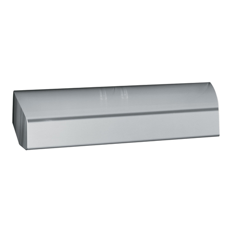
GE JV247 Operating instructions

0GEAppliances.com
Safety Information ........ 2,3
Operating/Care and
Cleaning Instructions
Charcoal Filter .................... 5
Grease Filter ..................... 4
Hood Light ....................... 5
Hood Surfaces ................... 5
Controls .......................... 4
Installation
Instructions ................ 6-14
Consumer Support
Consumer Support ..... Back Cover
Warrantg ....................... 15
JV247*-Vent &Recirculation
options
JV248*-Vent &Recirculotion
options
JN527-Recirculotion onlg
JV358*-Vent options only
JV347*-Vent &Recirculotion
options
JV348*-Vent &Recirculotion
options
JV367*-Vent &Recirculotion
options
RN528-Recirculotion only
|
CERTIFIED
Write the model and serial numbers here:
Model #
Serial #
Youcan find them on a label on the
back wall of the hood.
49-80589-1 08-09 JR

IMPORTANT SAFETY INFORMATION.
READ ALL INSTRUCTIONS BEFORE USING.
SAFETYPRECAUTIONS
^,,,,WARNING- ToREDUCETHERISKOF
FIRE,ELECTRICSHOCKORINJURYTOPERSONS,
OBSERVETHEFOLLOWING:
A. Usethisunit onlUinthe mannerintended
bg themanufacturer.If gouhavequestions,
contactthe manufacturer.
B. Beforeservicingor cleaningunit, switchpoweroff
atservicepanelandlocktheservicedisconnecting
meansto preventpowerfrom beingswitchedon
accidentallg.Whentheservicedisconnecting
meanscannotbelocked,securelgfastena
prominentwarningdevice,such asa tag,to
theservicepanel.
C. Donotusethis unitwith ang solid-statespeed
controldevice.
D. Ifusinga cordconnectionkit,useonlywith range
hoodcord-connectionkitJXHC1that hasbeen
investigatedandfoundacceptablefor usewith
thismodelrangehood.
E. Thisunitmustbegrounded.
CAUTION-FORGENERALVENTILATING
USEONLY.DONOTUSETOEXHAUSTHAZARDOUSOR
EXPLOSIVEMATERIALSANDVAPORS.
WARNING- TOREDUCETHERISKOF
INJURYTOPERSONSINTHEEVENTOFA RANGETOP
GREASEFIRE,OBSERVETHEFOLLOWING*:
A. SMOTHERFLAMESwith a dose-fittinglid,cookie
sheetor metaltrag,thenturn off theburner.
BECAREFULTOPREVENTBURNS.
Iftheflamesdo notgoout immediatelg,EVACUATE
ANDCALLTHEFIREDEPARTHENT.
B. NEVERPICKUPAFLAHINGPAN-
Youmagbe burned.
C. DONOTUSEWATER,includingwet dishclothsor
towels-a violentsteamexplosionwillresult.
D. Usean extinguisherONLYif:
1. Youknowgou havea ClassABCextinguisher,
and goualreadgknowhowto operateit.
2. Thefireissmallandcontainedintheareawhere
itstarted.
3. Thefiredepartmentisbeingcalled.
4. Youcanfightthefirewith gourbackto an exit.
*Basedon "KitchenFiresafetgTips"publishedbg NFPA.
AkWARNING - TOREDUCETHERISK
OFARANGETOPGREASEFIRE:
A. Neverleavesurfaceunitsunattendedat high
settings.Boiloverscausesmokingandgreasg
spilloversthat magignite.Heatoilsslowlgonlow
ormediumsettings.
B. Alwagsturn hoodONwhencookingon high
heatorwhenflambeingfood(i.e.CrepesSuzette,
CherriesJubilee,PeppercornBeefFlamb_).
C. Cleanventilatingfansfrequentlg.Greaseshould
notbeallowedto accumulateon fanor filter.
D. Useproperpansize.Alwagsusecookware
appropriateforthesizeof thesurfaceelement.
AWARNING- TOREDUCETHERISK
OFFIRE,ELECTRICSHOCKORINJURYTOPERSONS,
OBSERVETHEFOLLOWING:
A. Installationwork and electricalwiring mustbe
donebg qualifiedperson(s)inaccordancewith
allapplicablecodesandstandards,including
fire-ratedconstruction.
B. Sufficientair isneededfor propercombustionand
exhaustingofgasesthroughtheflue(chimneg)of
fuelburningequipmentto preventbackdrafting.
Followtheheatingequipmentmanufacturer's
guidelineand safetgstandardssuchasthose
publishedbgthe NationalFireProtection
Association(NFPA),theAmericanSocietgfor
Heating,RefrigerationandAirConditioning
Engineers(ASHRAE)andthe localcodeauthorities.
C. Whencuttingor drillingintowallorceiling,do not
damageelectricalwiringandotherhiddenutilities.
D. Ductedfans mustalwagsbeventedtothe
outdoors.
AWARNING- ToREDUCETHERIsKOF
FIREANDTOPROPERLYEXHAUSTAIR,BESURETO
DUCTAIROUTSIDE--DONOTVENTEXHAUSTAIR
INTOSPACESWITHINWALLSORCEILINGSORINTO
ATTICS,CRAWLSPACESORGARAGES.
AWARNING- ToREDUCETHERISKOF
FIRE,USEONLYMETALDUCTWORK.
[] Donotattemptto repairor replaceangpartof gour
hoodunlessitisspecificallgrecommendedinthis
guide.Allotherservicingshouldbe referredtoa
qualifiedtechnician.
READAND FOLLOWTHISSAFETYINFORMATIONCAREFULLY.
READAND SAVETHESEINSTRUCTIONS

J J
INSTRUCTIONS DE SECURITE INIPORTANTES.
LISEZ TOUTES LES INSTRUCTIONS AVANT D'UTILISER.
. PRECAUTIONSEN tv1ATIEREDE SECURITE,,,,
A A! 1_'I3T'IC_IE'I_AI_'I_ IT" Ao Nelaissezjamais sans surveillance lesunit_s de
ill _ V L !_ I IJJIZ, l'l _,! V I _ POUR cuissonde surface a une temp@ature _lev_e.Le
REDUIRELERISQUED'INCENDIE,DESECOUSSE bouillonnement occasionne desd_bordements
" i _ \ _" ELECTRIQUEOUDE BLESSURECORPORELLE,OBSERVEZ fumants et graisseuxqui peuvent prendrefeu.
LESPRECAUTIONSSUIVANTES: Chauffez5feu doux lessubstances huileuses,
A. N'utilisezcet appareil que de la mani@epr_vue par
lefabricant. Sivousavezdes questions,appelez
lefabricant.
B. Avantde r_parerou de nettoger votre appareil,
d_branehezlecourant au niveaudu panneau
deserviceetverrouillez lesm_canismesde
d_branchement deservice pour @iter tout
branchement accidentel au courant. Sivous nepouvez
pasverrouiller lesm_canismesde d6branehement de
service,attachez soigneusement un avertissementbien
visible,comme une _tiquette, au panneau deservice.
C. N'utilisezjamais cet appareil avec un m_canisme
de r_glagede la vitesse5 semi-conducteurs.
D. SivousutilisezI'ensemblede cordon de raccordement,
utiliseseulement avec I'ensemblede cordon de
raccordement pour hotte JXHC1.Suite6 un examen
technique, I'articleJXHC1s'est av@_compatible avec
ce module de hotte.
E. Cetappareildoit _trebien mis 6 la terre.
_kATTENTION- UNIQUEMENTAUSAGE
DEVENTILATIONGENERALE.N'UTILISEZJAMAISPOUR
L'ECHAPPEMENTDEMATIERESETDEVAPEURS
EXPLOSIVES.
_kAVERTISSENENT- Pour
RE'DUIRELERISQUEDEBLESSURECORPORELLESIDE
LAGRAISSEPRENDFEUSURLASURFACEDECUISSON
DELACUISINIERE,SUIVEZLESINSTRUCTIONS
SUIVANTES*:
A. ETOUFFEZLESFLAMMESavec un couvercle qui
convient, unet61e5biscuits ou un plateau en m@tal,
puis@teignez[ebrOleur.FAITESBIENATTENTIONDENE
PASVOUSBRULER.Silesflammes ne s'@teignentpas
imm@diatement,SORTEZETAPPELEZLESPOHPIERS.
B. NEDEPLACEZJAHAISUNECASSEROLLEQUI FLAHBE-
Vouspouvezvous brOler.
C. N'UTILISEZJAHAISD'EAU,en particulier de serviette
ou de chiffon mouill@-il se produira une explosion
violentede vapeur brOlante.
D. N'UTILISEZUNEXTINCTEURquesi:
1. Vousavez un extincteur de closseABCet vous
savezcomment I'utiliser;
2. Lefeu est r_duit et confin_ 6 I'endroitoQil a
commenc&
3. Vousavez d_j5 appel_les pompiers;
a,. Vouscombattez lesflammes en tournant le dos
a unesortie.
* Bas6sur I'ouvrageintitul_ <<KitchenFireSafetg Tips>>
publi_par la NFPA.
AVERTISSENENT- Pour
REDUIRELERISQUED'UNFEUDEGRAISSESUR
LASURFACEDECUISSONDELA CUISINIERE:
avecun r_glage bas ou mogen.
B. ALLUHEZtoujoursla hotte en casde cuisson5
feu _lev_ou Iorsquevousfaites flamber des aliments
(parexemple,cr_pesSuzette,cerisesjubilees,boeuf
au poivreflamb_).
C. Nettoyezles m_canismes de ventilation fr_quemment.
IInefaut pas permettre uneaccumulation de graisse
sur leventilateur ou sur lefiltre.
D. Utilisezune casserolede bonne taille. Utiliseztoujours
un ustensiledecuisinequi convienne au diam_tre
deI'_l_ment de cuisson.
,&AVERTISSEIENT - POUR
RE'DUIRELERISQUED'INCENDIE,DESECOUSSE
ELECTRIQUEOUDEBLESSURECORPORELLE,OBSERVEZ
LESPRECAUTIONSSUIVANTES:
A. Vousdevezfaire ex_cuter tous lestravaux d'installation
et de c6blage _lectrique par une personnequalifi6e,
conform_ment 5 tousles codes et les normesen
vigueur,en particulier ceux de construction relatifs
aux incendies.
B. Vousdevez assezd'air pour avoirune bonne
combustion et permettre I'@aeuationdesgaz par le
conduit de chemin_e du mat@ielde combustion du
carburant, afin d'@iter tout retour d'air.Suivezles
directivesdu fabricant de mat@iel de combustion
et les normesde s_curit_ comme cellespubli_es
par la National FireProtectionAssociation(NFPA),
I'AmericanSocietyfor Heating, Refrigerationand
AirConditioning Engineers(ASHRAE),ainsique les
modalit_s descodesIocaux.
C. Sivous faites un trou ou une ouverture dans un mur
ou un plafond,n'endommagez pas lesills _lectriques
et lesautres installations cach_esde service public.
D. Vous deveztoujours alimenter lesventilateurs dans
lesconduits en air en provenance de I'ext@ieur.
_I,AVERTISSENENT- POUR
RE'DUIRELERISQUED'INCENDIEETEVACUER
ADEQUATENENTL'AIR,ASSUREZ-VOUSDEFAIRE
DEBOUCHERLACONDUITED'AIRAL'EXTERIEUR--
NE VENTILEZPASL'AIREVACUEDANSDESESPACES
COHPRISA L'INTERIEURDEHURS,D'UNPLAFOND,
D'UN GRENIER,D'UNVIDESANITAIREOUD'UN GARAGE.
_i,AVERTISSEIENT - POUR
RE'DUIRELERISQUED'INCENDIE,N'UTILISEZQUE
DESCONDUITSENPIETAL.
[] N'essagezjamais de remplacer ou de r@arer un
@l@mentde votre hotte si le pr@sentmanuel ne le
recommande pas express@ment.Toutautre entretien
doit @treeffectu@par un technicien qualifi&
LISEZETSUIVEZATTENTIVEMENTCESINSTRUCTIONS.
LISEZETCONSERVEZCESINSTRUCTIONS ]

Using the hood controls.
Throughout this manual, features and appearance may vary from your model.
Control Knobs Ion some models) Switch Pad Controls Ion some models)
OFF OFF
LO_Hi _ON
MED NITE OFF
HI
_Ip OFF
LO
FAN Control @
Turn to HI, MED or LO as needed.
Continuous use of the fan system while cooking _1
helps keep the kitchen comfortable and less humid.
It also reduces cooking odors and soiling moisture
that create a frequent need for cleaning.
LIGHT Control
Turn to ONwhile cooking or to NITEfor use as
a night light.
LIGHT Control
Pressthe pad at the top to turn the light ON.
FAN Control
Pressthe pad at the top to turn the fan on HI and at
the bottom to turn it on LO.The center position isOFF.
Continuous use of the fan system while cooking
helps keep the kitchen comfortable and less humid.
It also reduces cooking odors and soiling moisture
that create a frequent need for cleaning.
Care and cleaning of the vent hood.
Be sure electrical power is off and all surfaces are cool before cleaning or servicing ang part of the
vent hood.
Reusable Metal Grease Filter--Ducted Installations On/g
Greasefilter
The efficiency of your hood
depends on a clean filter. Frequency
of cleaning depends on hood use
and the type of cooking you do.
However, the grease filter should
be cleaned at least once amonth.
To remove:
Pull down on the center of the front
edge of the filter. The filter will then
slip out of the retaining tabs on the
back.
To replace:
Slip the back edge of the filter into
the retaining tabs and push the
front edge up until it snaps into
place.
Todean:
Soak and then agitate it in a hot
water and detergent solution. Light
brushing can be used to remove
embedded dirt. Rinse,shake and
let it dry before replacing.
NEVEROPERATETHEHOOD
WITHOUT THEFILTERIN PLACE.
With careful handling, the metal
filter will last for gears. If a new
replacement filter becomes
necessary, order the part from
your dealer. Order genuine GE
part number WBO2X8391.
q

Replaceablecharcoalfilter
NOTE:DONOT rinse, or put chorcoa!
filters in on automatic dishwasher.
Charcoal Filter-Recirculating Installations Only
Thecharcoalfilter cannotbecleaned.
It mustbereplaced.Orderfilter no.
WBO2XI0700.Replacementfilters
canbeorderedfromyour GEsupplier.
Ifthehoodisnotventedtotheoutside,
theair willberecirculatedthrougha
disposablecharcoalfilterthat helps
removesmokeandodors.
Thecharcoalfiltershouldbereplacedafter
6to 12months(dependingonhoodusage).
Toremove:
Pulldownonthecenterofthefrontedge
ofthefilter.Thefilterwillthenslipoutof
theretainingtabsontheback.
Toreplace:
Slipthebackedgeofthefilterintothe
retainingtabsandpushthefront edge
upuntilitsnapsintoplace.
Stainless Steel Surfaces (onsome
Do not use a steel-wool pad, it will
scratch the surface.
Tocleanthestainlesssteelsurface, use
warmsudsgwateror astainlesssteel
cleanerorpolish.Alwauswipethesurface
inthedirectionofthegrain.Followthe
cleanerinstructionsforcleaningthe
stainlesssteelsurface.
models)
Toinquireaboutpurchasingstainlesssteel
appliancecleaneror polish,ortofindthe
locationofa dealernearestyou,please
callourtoll-freenumber:
NationalPartsCenter
800.626.2002
GEAppliances.com
Painted Surfaces (on some models)
Do not use steel-wool pads or other
abrasive cleaners. They will scratch
the surface.
Cleangrease-ladensurfacesofthehood
frequently.Tocleanthehoodsurface,use
a hot,dampclothwitha milddetergent
suitableforpaintedsurfaces.Aboutone
tablespoonofammoniamay beaddedto
thewater.Usea clean,hot,dampclothto
removesoap.Drywitha dry,cleancloth.
NOTE:Whencleaning,takecarenotto
comeincontactwith filtersandother
non-enameledsurfaces.
,_ CAUTION: Whencleaning
thehoodsurfaces,becertainthatyoudo
nottouchthelightbulbwithmoisthands
orcloth.A warmorhotlightbulbmay
breakiftouchedwith amoistsurface.
Alwaysletthelightbulbcoolcompletely
beforecleaningaroundit.
iht cover
Whenusingan energysavingbulbin yourGEhood
makesureyouuseeither:
GELongLifeEnergySmarf"SpiraPT2
ProductCode:85183
Description:FLE1SHT2/2/SW/CD
or
GELongLifeEnergySmarf"A17
ProductCode:47486
Description:FLE11/2/A17XL/CD
Availableatwww.gelighting.com
Hood Light
^H CAUTION:Letthelightbulb
coolcompletelybeforeremoving.A
warmor hotbulbmay breakiftouched
witha moistclothorhand.
Removethebulbandreplaceit with
atypeA15incandescentlightbulbwith
anordinaryscrewbase,notmorethan
60 Watts,or atype A17or72Compact
Fluorescent(CFL)lightbulbwithan
ordinaryscrewbase,notmorethan
13Watts.NOTE:Useonlyincandescent
bulbsinmodelsRN528,JN527andJV558.
IMPORTANT:Forinstallation,handling
anddisposalprecautions,refertothe
fluorescentbulbpackagingliterature.
Toremovethelight cover
(onsomemodels):
• Pressthesideswithtwo fingersuntil
thesideprongsarereleased.
• Liftthelightcoverandslideittoward
youinonemotion.
Toreplacethelight cover:
,, Insertthe pronglocatedattheend
ofthecoverintothetopopening.
• Gentlypushthecoverupand pressthe
sidestofit thesideprongsintotheside
openings.
• Releaseandthecoverwilllockinposition.

w
I stallti
Istr cti Ra e Hood
IQuestions? Col/800oGEoCARES (800.432.2737)orvisitourWebsiteat:GEApplJances.com 1
BEFORE YOU BEGIN
Read theseinstructionscompletelyand carefully.
" IMPORTANT - Savetheseinstructions
for local inspector's use.
"IMPORTANT - Observe all governing
codes and ordinances.
, Note to Installer - Be sure to leave these
instructions with the Consumer.
, Note to Consumer - Keepthese instructions
for future reference.
, Skill level - Installation of this appliance requires
basic mechanical and electrical skills.
, Completion time - 50 minutes-] hours
. Proper installation is the responsibilitg of the installer.
. Product failure due to improper installation is not
covered under the Warrantg.
FOR YOUR SAFETY:
-AWARNING - Before beginning the
installation, switch power off at service panel and
lock the service disconnecting means to prevent power
from being switched on accidentallg. When the service
disconnecting means cannot be locked, securelg fasten
a prominent warning device, such as a tag, to the
service panel.
OPTIONAL POWER CORD KIT JXHC$
An optional Power Cord Connection Kit, model JXHC1,
is available at extra cost from gour GEsupplier for
installation using a standard ]-prong, grounded wall
outlet. Follow the Installation Instructions packed with
the kit to connect the power cord to the range hood.
DUCTWORK REQUIREMENTS
NOTE:Readthe ductwork sectionsonlg if gou do not
have existing ductwork. If gou have existing ductwork,
skip to the "Damage" section and proceed.
AWARNING- ToREDUCETHERISKOFFIREAND
TO PROPERLYEXHAUSTAIR,BESURETO DUCT AIROUTSIDE--
DO NOT VENTEXHAUSTAIRINTOSPACESWITHINWALLS OR
CEILINGSOR INTOATTICS,CRAWL SPACESOR GARAGES.
Theventing system must exhaust to the outside.
This hood can be vented verticallg through upper cabinets
or horizontallg through an outside wall. Ductwork isnot
included.
Exhaust connection:
The hood exhaust has been designed to mate with
standard 3_/4"x 10" rectangular ducting or 7" diameter
round ducting.
If a 6" round duct isrequired, a rectangular-to-round
transition adaptor must be used*. Do not use less than
a 6" diameter duct.
Maximum duct length:
Forsatisfactorg air movement, the total duct length
of a 3V4"x 10" rectangular, 6" or 7" diameter round
duct should not exceed 65 equivalent feet. Seethe
WORKSHEET-CALCULATETOTALEQUIVALENT
DUCTWORKLENGTHsection.
NOTE:It isimportant that ducting be installed using
the most direct route and with as few elbows as possible.
This ensures clear venting of exhaust and helps prevent
blockages. Also, make sure dampers swing freel# and
nothing is blocking the ducts.
Elbows, transitions, wall and roofcaps, etc.,
present additional resistance to airflow and are equivalent
to a section of straight duct longer than their actual
physical size.When calculating the total duct length, add
the equivalent lengths of all transitions and adaptors plus
the length of all straight duct sections. Thecharts on the
following pages show you how to calculate total equivalent
ductwork length using the approximate feet of equivalent
length of some typical ducts.
IMPORTANT:Ifa rectangular-to-round
transition adaptor isused, the bottom
corners of the damper will have to be
cut to fit, using the tin snips,in order
to allow free movement of the damper.
Equivalent lengths of duct pieces
are based on actual tests and reflect
requirements for good venting
performance with any hood.
6

Installation Instructions
WORKSHEET--CALCULATE TOTAL EQUIVALENT DUCTWORK LENGTH
DUCT
PIECES
3W'x 10"
Rect.,
straight
7" Round,
straight
6" Round,
straight
EQUIVALENT NUMBER
LENGTH x USED
1Ft. x( )
1Ft. x( )
1Ft. x( )
= TOTAL
Ft.
Ft.
Ft.
i_ 3X'x 10" 14Ft. x ( ) = Ft.
Rect.90°
elbow
3X"x 10" 8Ft. x ( ) = Ft.
Rect.45°
elbow
3X"x 10" 33Ft. x ( ) = Ft.
Rect.90°
flat elbow
3W'x 10" 24Ft. x ( ) = Ft.
Rect. (18ft.w/o
wallcap damper) x ( ) = Ft.
with
damper
t__ 3W'x 10" 2Ft. x ( ) = Ft.Rect.to
6" round
transition
__ X"x 10" 4 Ft. x ( ) = Ft.
Rect.to
6" round
transition
90° elbow
(_ "Round, 25Ft. x ( ) = Ft.
90° elbow
(_ 6" Round, 16Ft. x ( ) = Ft.
45° elbow
Subtotalcolumn1 = Ft.
MAXIMUM DUCT LENGTH:For satisfactorg air movement,
the total duct length of a 3V/' x !0" rectangulQr, 7" diQmeter
round duct should not exceed 65 equivalent feet.
DUCT
PIECES
%
f5
6"Round
wall cap
with
damper
6" Round
roofcap
6"Round
to
3X'x 10"
rect.
transition
6"Round
to
3X'x 10"
rect.
transition
90° elbow
7"Round,
90° elbow
7"Round,
45° elbow
EQUIVALENT
LENGTH
7" Round
wall cap
with
damper
7" Round
roofcap
53Ft.
(39ft. w/o
damper)
72Ft.
3 Ft.
9 Ft.
14Ft.
9 Ft.
28Ft.
(21ft. w/o
damper)
NUMBER
x USED
x( )
x( )
x( )
x( )
x( )
x( )
x( )
= TOTAL
= Ft.
= Ft.
= Ft.
= Ft.
= Ft.
= Ft.
= Ft.
= Ft.
= Ft.
= Ft.
x( )
x( )
39Ft. x ( )
7"Round 1Ft. x ( ) = Ft.
to
3¼"x 10"
rect.
transition
7" Round
to
3X'x 10"
rect.
transition,
90° elbow
5Ft. x (
Subtotalcolumn2
Subtotalcolumn1
Total duct:work
Ft.
Ft.
Ft.
Ft.

Installation Instructions
DAMAGE- SHIPMENT/INSTALLATION
- If the unit is damaged in shipment, return the unit to the
store in which itwas bought for repair or replacement.
- If the unit is damaged by the customer, repair or
replacement isthe responsibility of the customer.
- If the unit is damaged bg the installer (ifother than
the customer), repair or replacement must be made
by arrangement between customer and installer.
MOUNTING SPACE
24", 30" or36" to 3
matchcooklopwidth m
Bottomedgeof
cabinetneeds
to be30" or
morefrom
the cooking
surface
66" or more
fromthefloor
tothetopof
thehood
NOTES:
- Hood width may be greater than the width of the range
or cooktop, but it may not be smaller.
- Ensurethe range or cooktop isinstalled per
manufacturer's installation instructions.
- If you are going to vent your range hood to the outside,
seethe "Ducting Requirements"section for exhaust duct
preparation.
TOOLS YOU WILL NEED
Flat-bladeand Phillips
screwdrivers
Saw(saberorkeyhole)
Pencil
Electricdrill
Duct tape
Metalsnips
(insome
applications)
1/4"pivoting
hexsocket Pliers Tapemeasure Wirestripper
Flashlight Caulking Level 1/4"Nutdriver
PARTS INCLUDED
PART QUANTITY
I
4
GreaseFilteronly(JV338)
CharcoalFilteronly
(JN327andRN328)
GreaseFilterandCharcoalFilter
(JV24X,JV347,JV348andJV367
MountingScrews
(8- 18"x3/4" Phillipspanhead)
ExhaustAdaptor
(for3W'x 10"rect.venting)
ExhaustAdaptorScrew
(8- 18"x 3/8" Phillipspanhead
orhexhead)
8

Installation Instructions
[_]CHOOSE VENT OPTION
Determine the vent option thQt your installation will
require and thQt is avQilQblefor your model from the
below choices.
IMPORTANT:If the hood isto be installed in a
redrculating, non-vented, ductless manner, do not
knock out ang vent openings in the hood. Onlg an
electrical access hole will be knocked out of the hood.
r_ outsidetop exhaust10"
{Verticalduct-3VJ'x Rectangular)
JV338
JV247
JV248
JV347
JV348
JV367
FC-]outside rearexhaust i0"
(Horizontalduct-3VJ'x Rectangular)
JV338
JV247
JV248
JV347
JV348
JV367
[_ Outside top exhaust
{Verticalduct-7" Round)
JV338
JV247
JV248
JV347
JV348
JV367
9
FD-] Recirculating
(non-vented/ductless)
JN327
RN328
JV247
JV248
JV347
JV348
JV%7

Installation Instructions
_-I REMOVE EXHAUST ADAPTOR
If exhausting/ventingusingthe3VJ'x10"rectangular
duct--optionalforJV247,JV248,JV338,JV347,JV348
and JV367modelsonlg:
Removethe exhaust adaptor from the insideof the hood.
Set it aside along with its mounting screws.
3W'x 10"
exhaust
adaptor
andscrews
_]REMOVE WIRING COVER
Removethe wiring cover from insidethe hood.
Setthe cover and its mounting screws aside.
Wiring
cover
i31REMOVE FILTER
Removethe shipping tape holding the metal grease
filter in place. Pulldown on the center of the front edge
of the filter.Thefilter will then slip out of the retaining
tabs on the back.
lMetalgreasefilter
[] REVERSE THE BAFFLE FOR DUCTED
INSTALLATIONS ONLY {JV247,JV248,
JV347, JV348 and JV367 models)
Ifthe hood isto be recirculated, skip to the next step.
Removethe baffle from the top of the hood. Reinstall
the baffle so the short side marked "VENTED"isvisible.
Thelong side of the baffle should be insidethe hood.
"VENTED"isvisible
FGlREMOVE WIRING KNOCKOUT
Removeeither the top or the back wiring knockout as
needed and install an approved strain relief clamp.
Topknockout Backknockout
Strainrelief
clamp
Strainrelief
clamp
Fi]REMOVE DUCT KNOCKOUT
If recirculating, non-vented ductless (JN327and RN328,
and optional for JV247,JV248,JV547,JV548 and JV567
models onlg),skip to Step 11 Dand proceed.
Using a flat-blade screwdriver, remove the appropriate
duct knockout from the top or back of the hood.
31/4'' X 10" Rectangular
vertical discharge.
Removetoprectangular
ductknockoutonly.
7" Round vertical
discharge. Remove circular
duct knockout only.
10
31/4"× 10" Rectangular
horizontal discharge. Remove
rear rectangular duct knockout only.

Installation Instructions
[_]FOR 3YJ'× 10" RECTANGULAR
DUCTED DISCHARGE INSTALLATIONS
ONLY:
Attach exhaustadaptoF/damperover the appropriate
knockout opening (for vertical or horizontal, depending
on installation) with two exhaust adaptor screws. Make
sure damper pivot is nearest to top/back edge of hood.
Removetape from damper flap.
Exhaustadaptor/damper
(verticaldischargeposition) Tape
Pivot
(dependingon Top/backedge
installation) Exhaustadaptor/damper
(horizontaldischargeposition)
[] FOR RECESSED-BOTTOM CABINETS
ONLY
Woodshims
(minimumthickness3/8")
• If the cabinets have front, side or back trim, make
2 wood shims a minimum of 3/8" thick and cut to
fit the width of the inner recessed cabinet bottom.
Attach them to the cabinet bottom recess on both
sides. See Step 11 for marking locations.
[_ FOR 7" ROUND VERTICAL DUCTED
DISCHARGE INSTALLATIONS ONLY:
Bend up the duct alignment ears in preparation for
later attachment of the 7" duct.
11

Installation Instructions
HARK HOLES
Select the vent option that your installation will require
and proceed to that section:
A. Outside top exhaust
{Verticalduct-3YJ' x i0" Rectangular)
• Use the diagram or the hood as a template and mark
the locations on the cabinet for ductwork, electrical
wiring and keyhole screw slots.
Hoodmountingscrews(4)
10%"(24"hood) 10r¼'' (24"hood)
13r¼'' (30"hood) 13r¼"(30"hood)
16r¼'' (36"hood) (36"
front
CabinelBottom
5¼" _,_ 51/4 '' _,_
| Verticalduct |
I accesshole |
\ Wood shimsf
(recessed-bottom
cabinetsonly_hims
mustbeaminimumof
3/8" thickand cut to fit
thewidth of theinner
recessedcabinetbottom)
Electricalaccesshole
Center (in cabinetbottom)
line
B.Outside top exhaust (Verticalduct-7" Round}
• Use the diagram or the hood as a template and
mark the locations on the cabinet for ductwork,
electrical wiring and keyhole screw slots.
Hoodmountingscrews(4)
10Y4"(24"hood) 10Y4"(24" hood)
13Y_"(30"hood) 13Y4"(30" hood)
(36"hood) hood)
Wood shims (recessed-bottom
cabinetsonly shimsmustbea Center
minimumof 3/8" thick andcut lille
to fit thewidth ofthe inner
recessedcabinetbottom)
Electricalaccess
hole(in cabinetbottom)
C. Outside rear exhaust
(Horizontalduct-3V4" x 10" Rectangular)
• Usethe diagram or the hood as a template and
mark the locations on the cabinet for ductwork,
electrical wiring and keyhole screw slots.
Woodshims
(recessed-bottomcabinetsonly shimsmustbea
minimumof3/8" thick andcut to fit the width
of theinner recessedcabinetbottom)
__,Lx_ Cabinetfront 'A" l_A" I I I
I accesshele I
hood)_10¾" (24"hood)
hood)J13_" (30"hood)
hood) ._ 16¾"(36"hood)
Hoodmountingscrews(4) Centerline Electricalaccesshole
(inwail)
D.Recirculating(non-ventedductless-
JN327 and RN328, and optional on JV247,
JV248, JV347, JV348 and JV367 models only)
• Usethe hood as a template and mark the locations
on the cabinet for the electrical wiring and keyhole
screw slots.
Since the hood is to be recirculated (not to be vented
outside), do not cut out any vent openings in the wall
or cabinet bottom.
[] CUT HOLES
Cut holes at marked locations for duct and electrical
wiring. Forthe vertical duct, cut out 3/4" extra toward
the front of the cabinet so you can move the duct
freely when installing the hood. It may also ease
installation by cutting the hole 10V2"instead of 10".
[] RUN WIRES
Runthe electrical wires through the wall or
cabinet according to National Electrical Code
and applicable local codes.
NOTE:DONOTturn the power on until installation
is complete.
12

Installation Instructions
[] SCREW IN PART WAY
Drive a mounting screw (from the hardware packet)
part wag into each center of the narrow neck of the
keghole slots marked on the cabinet bottom.
[] OPTIONAL POWER CORD
KIT JXHC1
An optional Power Cord Connection Kit, model
JXHC1, isavailable at extra cost from gour GE
supplier for installation using a standard ]-prong,
grounded wall outlet. Follow the Installation
Instructions packed with the kit to connect the
power cord to the range hood.
Cabinet
3-prong
outlet
(if usingcord
connection)
1:_" dia. clearance hole
for optional power
supply location
NOTE:If using optional Power Cord Kit JXHC1,feed
the power cord through the hole in the top cabinet
while raising the hood. Loop ang excess length of
cord and tie awag with a suitable tape or tie.
r_ FEED IN WIRES
Lift the hood into position and feed the house wiring
through the wiring knockout.
[] SECURE HOOD
Slide the hood back against the wall. Tighten the
mounting screws. Be sure the screw heads are in
the narrow neck of the keghole slot.
CD
Keyhole(4)
NOTE:DO NOTPUSHON THE FANBLADE.Pushing on
the blade mag cause it to interfere with other hood
parts.
[] CONNECT DUCTWORK TO HOOD
(Ducted installations onlg)
On 7" round installations, attach the 7" duct
with sheet metal screws through the holes in
the alignment ears.
_-- 7" roundduct
Useduct tape to make joints secure and airtight.
13

Installation Instructions
[] INSTALL LIGHT BULB
NOTE:A light bulb is not shipped with the hood.
Obtain one locally. Purchase and install a type A15
incandescent light bulb with an ordinary screw base,
not more than 60 Watts, or a type A17 or T2
Compact Fluorescent (CFL)light bulb with an ordinary
screw base, not more than 13 Watts. NOTE:Useonly
incandescentbulbsin modelsRN328,JN327and JV338.
IMPORTANT:Forinstallation,handlinganddisposalprecautions,
refertothefluorescentbulbpackagingliterature.
Whenusinganenergysavingbulbin yourGEhood,makesureyou use
either:
GELongLifeEnergy
SmarCSpiral®T2
ProductCode:85383
Description:
FLE13HT2/2/SW/CD
GELongLifeEnergy
SmarfMA17
ProductCode:47486
Description:
FLElt/2/At7XL/CD
Availableat
www.gelighting.com
[2-0-1FOLLOW ELECTRICAL CODE
Complete the electrical wiring according to National
Electrical Code and local codes.
NOTE:This hood must be permanently grounded.
Connect house wiring (120 VAC)to hood wiring.
[] CONNECT WIRING
Connect house black to hood black wire, house white
to hood white wire and house ground under green
ground screw. Securely tighten the strain relief clamp
onto the house wiring.
Green groundscrew
ii, WARNING: IMPROPER CONNECTION OF
ALUMINUM HOUSE WIRING TO THESE COPPER LEADS
CAN RESULTIN A SERIOUS PROBLEM. USEONLY
CONNECTORS DESIGNED FOR JOINING COPPER TO
ALUMINUM AND FOLLOW THE MANUFACTURER'S
RECOMMENDED PROCEDURE CLOSELY.
[] REPLACE WIRING COVER
Wiringcover
[] REPLACE FILTER
Make sure fan blade turns freely and replace the filter.
NOTE:Install the metal grease filter if ducted or the
charcoal filter if recirculated.
Metalgreasefilterorcharcoalfilter
The installation is complete. Turn on power at service
panel, and test for proper operation.
1L
TROUBLESHOOTING CHECKLIST
If the hood seems to be operating at high speed when
the control is not set on high, or if ventilation seems
inadequate, check the following:
rj Knockouts not removed from hood.
rj Damper blade not opening.
rj Reduced airflow because the duct istoo small or
the duct length is too long.
rj The duct is blocked.
rj Undersized or restrictive wall or roof cap.
If the hood seems to make excessive noise:
rj Fan may be hitting the filter. Turn off the fan and
remove the filter. Bend the filter down slightlg in the
center (into a dome shape) to allow fan clearance.
Reinstall and adjust as needed.
The fan does not work but the lights do:
rj Switch power off at the service panel and lock the
service disconnecting means to prevent power from
being switched on accidentally. When the service
disconnecting means cannot be locked, securely
fasten a prominent warning device, such as a tag,
to the service panel.
rj Check the wiring connections. Seethe CONNECT
WIRINGsection in these Installation Instructions.

GE Range Hood Warranty.
All warrant_l service provided bg our Factors Service Centers, or
an authorized Customer Care ®technician. To schedule service,
visit us on-line at GEAppliances.com, or call 800.GE.CARE5
(800.432.2737). Please have serial number and model number
available when calling for service.
Staple your receipt here.
Proof of the origina! purchase
date is needed to obtain service
under the warranty.
GE Will Replace:
Ang part ofthe range hood which fails due to a defect in materials or workmanship.
Fromthe doteof the During this limited one-year warrants, GEwill also provide,free of charge, all labor and
Origino!purchose in-home serviceto replacethe defective part.
One Year
[] Service trips to gout home to teach SOUhow to use
the product.
[] Improper installation, delivers or maintenance.
[] Failure of the product ifit is abused, misused, or
used for other than the intended purpose or used
commemiallg.
[] Replacement of house fuses or resetting of dmuit
breakers.
[] Damage to the product caused bg accident, fire, floods
or acts of God.
[] Incidental or consequential damage caused bg possible
defects with this appliance.
[] Damage caused after delivers.
[] Product not accessible to provide required service.
EXCLUSION OF IMPLIED WARRANTIES--Your sole and exclusive remedy is product repair as provided
in this Limited Warrants. Any implied warranties, including the implied warranties of merchantability
or fitness for aparticular purpose, are limited to one gear or the shortest period allowed bg law.
This warranty is extended to the original purchaser and any succeeding owner for products purchased for
home use within the USA. Ifthe product is located in an area where service by a GE Authorized Servicer is not
available, you may be responsible for a trip charge or you may be required to bring the product to an Authorized GE
Service Location for service. In Alaska, the warranty excludes the cost of shipping or service calls to your home.
Some states do not allow the exclusion or limitation of incidental or consequential damages. This warrant_l
gives _lOUspecific legal rights, and _lOUma_l also have other rights which var_l from state to state. To know
what _tour legal rights are, consult _tour local or state consumer affairs office or _tour state's Attorne_t General.
Warrantor: General Electric Company. Louisville, KY 40225
15

Consumer Support.
GEAppliances Website GEAppliances.com
Have a question or need assistancewith your appliance?Try the GEAppliancesWebsite 24 hours a day,
any day ofthe year! Forgreater convenience and faster service,you can now download Owner's Manuals,
order parts or evenschedule service on-line.
Schedule Service GEAppliances.com
Expert GErepair service isonly one step away from your door.Geton-line and schedule your serviceat
your convenience any day of the year! Or call 800.GE.CARES(800./432.2737)duringnormal businesshours.
RealLifeDesignStudio GEAppliances.carn
GEsupports the UniversalDesignconcept-products, services and environments that can be usedby
people of all ages, sizesand capabilities.We recognizethe need to design for a wide range of physical and
mental abilities and impairments. Fordetails of GE'sUniversalDesignapplications, including kitchendesign ideas
for people with disabilities,check out our Website today. Forthe hearing impaired, pleasecall 800.TDD.GEAC
(800.855.4522).
Extended Warranties GEAppliances.cam
Purchasea GEextended warranty and learn about special discounts that are available while your warranty
isstill in effect. You can purchase it on-line anytime, or call800.626.222/4during normal businesshours.
GEConsumer Home Serviceswill still be there after your warranty expires.
Parts and Accessories GEAppliances.com
Individualsqualified to servicetheir own appliances can have parts or accessoriessent directly to their homes
(VISA,MasterCardand Discovercards are accepted).Orderon-line today, 24 hours every day or
by phone at 800.626.2002during normal businesshours.
Instructions contained in this manual cover procedures to be performed by any user. Other servicing
generally should be referred to qualified service personnel. Caution must be exercised, since improper
servicing may cause unsafe operation.
Contact Us GEAppliances.com
If you are not satisfiedwith the service you receivefrom GE,contact uson our Website with all the details
including your phone number,or write to: General Manager,Customer Relations
GEAppliances,Appliance Park
Louisville,KY/40225
Register Your Appliance GEAppliances.corn
Register gour new appliance on-line-at gour convenience! Timely product registration will allow for
enhanced communication and prompt serviceunder the terms of your warranty, should the need arise.
Youmay alsomail inthe pre-printed registration card included inthe packing material.
Printed in China
Other manuals for JV247
2
This manual suits for next models
7
Table of contents
Other GE Ventilation Hood manuals

GE
GE JVX3300 Original instructions

GE
GE UVW8361 Original instructions

GE
GE JV356 30 Technical manual

GE
GE JV930SCBR Training manual

GE
GE Monogram ZV30R User manual

GE
GE UVC9480 Original instructions

GE
GE Monogram ZV1050 User manual

GE
GE JVW5301, JVW5361 User manual

GE
GE Appliances CV936 Original instructions

GE
GE Profile JVB98SHSS User instructions