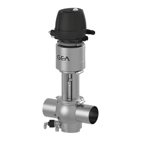
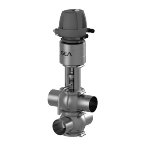
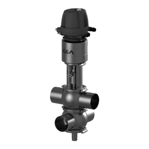
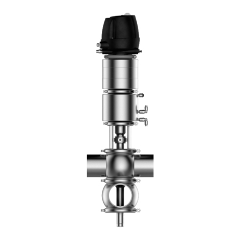
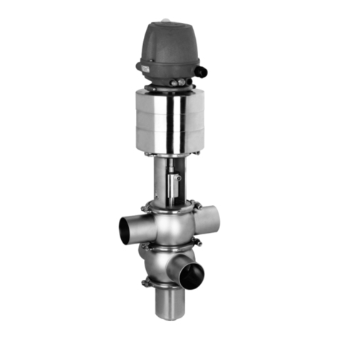
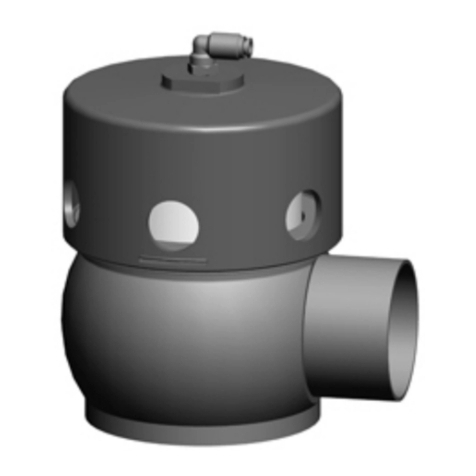
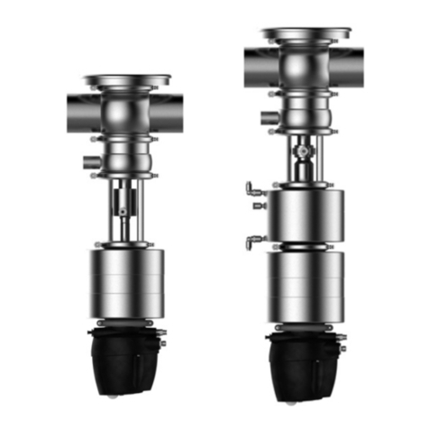
GEA VARIVENT T R Series User manual

Manual de instruções /Operating Instructions
VARIVENT®Válvula de fundo de sede dupla T_R/T_RL/T_RC
VARIVENT®Mixproof Bottom Valve T_R / T_RL / T_RC
Edição/Issue 09-2015
Português/English
GA Mechanical Equipmentengineering for a better world

09-2015 · Válvula de fundo de sede dupla T_R / T_RL / T_R / Mixproof Bottom Valve T_R / T_RL / T_RC

Índice
Abreviaturas e termos importantes ...................... 2
Instruções de segurança ......................................... 4
Utilização adequada............................................ 4
Pessoal .................................................................. 4
Modificações, peças de substituição, acessórios .... 4
Instruções gerais .................................................. 4
Identificação das instruções de segurança
no manual de instruções .................................... 5
Outros símbolos .................................................. 5
Zonas de especial perigo .................................... 6
Utilização específica ................................................ 7
Transporte e armazenamento ................................ 7
Verificar o fornecimento .................................... 7
Pesos .................................................................... 7
Transporte ............................................................ 8
Armazenamento .................................................. 8
Estrutura e funcionamento .................................... 9
Estrutura .............................................................. 9
Funcionamento .................................................. 12
Montagem e operação .......................................... 14
Posição de montagem ...................................... 14
Módulo de controlo .......................................... 14
Soldar a ligação da caixa no depósito .............. 15
Soldar a caixa na tubagem................................ 16
Conexão pneumática ........................................ 17
Plano de colocação de tubagem do módulo
de controlo T.VIS ................................................ 18
Plano de colocação de tubagem sem módulo
de controlo ..........................................................19
Conexão elétrica ................................................ 21
Colocação em funcionamento .......................... 21
Limpeza e passivação ............................................ 22
Limpeza .............................................................. 22
Passivação .......................................................... 23
Avarias, causas, soluções ...................................... 25
Manutenção .......................................................... 26
Inspecções .......................................................... 26
Intervalos de manutenção ................................ 26
Antes de desmontar .......................................... 27
Desmontar a válvula T_RL e T_RC .................... 28
Desmontar a válvula T_R .................................. 32
Manutenção ...................................................... 34
Montar a válvula T_RL e T_RC .......................... 37
Montar a válvula T_R ........................................ 41
Verificar o ciclo .................................................. 42
Dados técnicos ...................................................... 44
Extremidades de tubos– Sistema VARIVENT®.. 45
Conexão para limpeza ...................................... 46
Resistência dos materiais das juntas ................ 46
Lista de ferramentas/lubrificante...................... 48
Anexo
Listas de peças de substituição, válvulas T_R e T_RL e T_RC
Listas de peças de substituição/instrução de solda-
gem do fabricante
Declaração de incorporação
Contents
Important Abbreviations and terms ...................... 2
Safety Instructions .................................................. 4
Designated Use .................................................... 4
Personnel.............................................................. 4
Modifications, spare parts, accessories .............. 4
General instructions ............................................ 4
Marking of safety instructions in the operating
manual.................................................................. 5
Further symbols.................................................... 5
Special hazardous spots ...................................... 6
Designated Use........................................................ 7
Transport and Storage ............................................ 7
Checking the consignment ................................ 7
Weights ................................................................ 7
Transport .............................................................. 8
Storage ................................................................ 8
Design and Function................................................ 9
Design .................................................................. 9
Function.............................................................. 12
Assembly and Operation ...................................... 14
Installation position .......................................... 14
Control module.................................................. 14
Welding the housing connection into the tank 15
Welding the housing into the pipe .................... 16
Pneumatic connections .................................... 17
Hosing diagramm Control module T.VIS.......... 18
Hosing diagramm withoutControl module .... 20
Electrical connections ........................................ 21
Commissioning .................................................. 21
Cleaning and passivation...................................... 22
Cleaning ............................................................ 22
Passivation.......................................................... 23
Malfunction, Cause, Remedy................................ 25
Maintenance .......................................................... 26
Inspections.......................................................... 26
Maintenance intervals ...................................... 26
Prior to dismantling the valve .......................... 27
Dismantling the valve T_RL and T_RC.............. 28
Dismantling the valve T_R .............................. 32
Maintenance ...................................................... 34
Mounting the valve T_RL and T_RC ................ 37
Mounting the valve T_R.................................... 41
Checking the valve stroke ................................ 42
Technical Data ........................................................ 44
Pipe ends – VARIVENT®system.......................... 45
CIP Connection .................................................. 46
Resistance of the sealing material .................... 47
List of tools / Lubricant...................................... 48
Annex
Spare parts lists valves T_R and T_RL and T_RC
Spare parts list / Manufacturer’s Welding
Instructions
Declaration of Incorporation
09-2015 · Válvula de fundo de sede dupla T_R / T_RL / T_R / Mixproof Bottom Valve T_R / T_RL / T_RC 1
09-2015 · Válvula de fundo de sede dupla T_R / T_RL / T_R / Mixproof Bottom Valve T_R / T_RL / T_RC
2
Abreviaturas e
termos importantes
BS Padrão britânico
bar Unidade de medida da pressão
Todas as indicações de pressão [bar/psi] desig-
nam a sobrepressão [barg/psig] desde que não
seja explicitamente descrito nada em contrário.
aprox. aproximadamente
°C Unidade de medição para a temperatura
Graus Celsius
dm3nUnidade de medição para o volume
Decímetro cúbico
Volume de norma (litros de norma)
1dm3n= 1ln¯61inch3
DN Diâmetro nominal DIN
DIN Norma alemã do
DIN Deutschen Institut für Normung e.V.
EN Norma Europeia
EPDM Designação do material
Abreviatura conforme DIN/ISO 1629
Borracha de etilenopropilenodieno
°F Unidade de medição para a temperatura
Graus Fahrenheit
FKM Designação do material
Abreviatura conforme DIN/ISO 1629
Borracha fluorocarbonada
hUnidade de medição para o tempo
Hora
HNBR Designação do material
Abreviatura conforme DIN/ISO 1629
Borracha de acrilonitrilo-butadieno hidrogenado
IP Tipo de protecção
ISO Norma internacional da
Organização Internacional de
Normalização
kg Unidade de medição para o peso
Quilograma
kN Unidade de medição para a força
Quilonewton
Valor Kv Coeficiente de débito [m³/s]
1 KV = 0,86 x Cv
Important Abbrevia-
tions and Terms
BS British standard
bar Unit of measure for pressure
All pressure ratings [bar/psi] stand for
over pressure [barg/psig] if this is not explicitly
described differently.
approx. approximately
°C Unit of measure for temperature
degrees centigrade
dm3nUnit of measure for volume
cubic decimetre
Volume (litre) under standard conditions
1dm
3n= 1 ln¯61 inch3
DN DIN nominal width
DIN Deutsche Norm (German standard)
DIN Deutsches Institut für Normung e.V.
(German institut for Standardization)
EN European standard
EPDM Material designation
Short designation acc. to DIN/ISO 1629
Ethylene propylene diene (monomer) rubber
°F Unit of measure for temperature
degrees Fahrenheit
FKM Material designation
Short designation acc. to DIN/ISO 1629
Fluorine rubber
h Unit of measure for time
hour
HNBR Material designation
Short designation acc. to DIN/ISO 1629
Hydrated acrylonitrile butadiene rubber
IP Protection class
ISO International standard of the
International Organization for
Standardization
kg Unit of measure for weight
kilogram
kN Unit of measure for force
kilo Newton
Cv-Wert flow coefficient [US gallons per minute]
1 Cv = 1,17 x Kv

09-2015 · Válvula de fundo de sede dupla T_R / T_RL / T_R / Mixproof Bottom Valve T_R / T_RL / T_RC 3
l Unidade de medição para o volume
Litro
max. máximo
mm Unidade de medição para o comprimento
Milímetro
μm Unidade de medição para o comprimento
Micrómetro
M métrico
Nm Unidade de medição para o trabalho
Newton-metro
Dados para o binário de aperto
1 Nm = 0,737 lb.ft.
Pound-Force/libra-força (lb) + Feet/Pés (ft)
PA Poliamida
PE-LD Polietileno de baixa densidade
PTFE Politetrafluoretileno
psi Unidade de medida da pressão
Todas as indicações de pressão [bar/psi] desig-
nam a sobrepressão [barg/psig] desde que não
seja explicitamente descrito nada em contrário.
SET-UP Instalação com função de auto-aprendizagem
Durante a colocação em funcionamento e a
manutenção, o SET-UP realiza todos os ajus-
tes necessários para gerar mensagens.
AC Indicação do tamanho da chave de ferramentas
Abertura da chave
v. cap. ver capítulo
v. fig. ver figura
T.VIS®Tuchenhagen Ventil Informations-
System (sistema de informação sobre válvulas
Tuchenhagen)
V DC Volt direct current = corrente contínua
V AC Volt alternating current = corrente alterna
W Unidade de medição para a potência
Watts
GIV Processo de soldadura
Soldar com gás inerte de volfrâmio
Polegada Unidade de medição para o comprimento
no espaço linguístico inglês
Polegada Medida de tubos segundo a norma britânica
OD (BS), Outside Diameter
Polegada Dimensão do tubo de acordo com a norma
IPS americana
Iron Pipe Size
l Unit of measure for volume
litre
max. maximum
mm Unit of measure for length
millimetre
μm Unit of measure for length
micrometre
M metric
Nm Unit of measure for work
Newton metre
Unit for torque
1 Nm = 0.737 lb.ft.
Pound-Force (lb) + Feet (ft)
PA Polyamide
PE-LD Polyethylene low density
PTFE Polytetrafluoroethylene
psi Unit of measure for pressure
All pressure ratings [bar/psi] stand for
over pressure [barg/psig] if this is not explicitly
described differently.
SET-UP Self-learning installation
For commissioning and maintenance the
SET-UP procedure carries out all necessary
settings for the generation of messages.
Size Size of spanners
(width across flats)
see Chapt. see Chapter
s. ill. see illustration
T.VIS®Tuchenhagen Valve Information System
V DC Volt direct current
V AC Volt alternating current
W Unit of measure for
Watt
TIG Welding method
tungsten inert-gas welding
Inch Unit of measure for length
in English-speaking countries
Inch OD Pipe dimension acc. to British standard
(BS), Outside Diameter
Inch IPS US pipe dimension
Iron Pipe Size

09-2015 · Válvula de fundo de sede dupla T_R / T_RL / T_R / Mixproof Bottom Valve T_R / T_RL / T_RC
4
Instruções de
segurança
Utilização adequada
A válvula está concebida apenas para a utilização espe-
cífica descrita. Qualquer outra utilização será considera-
da utilização inadequada. A Tuchenhagen não se
responsabiliza por danos resultantes de uma utilização
indevida; a entidade exploradora é a única responsável.
As condições para uma operação correcta e segura da
válvula são um transporte e armazenamento adequa-
dos, assim como uma instalação e montagem realizada
por técnicos competentes.
Uma utilização adequada inclui também o cumprimento
das instruções de operação, manutenção e inspecção.
Pessoal
O pessoal responsável pela operação e manutenção tem
de dispor de qualificação adequada para a realização
destes trabalhos. Deve ainda ser informado sobre possí-
veis perigos, bem como conhecer e cumprir as instruçõ-
es de segurança indicadas na documentação.
Os trabalhos no sistema eléctrico só devem ser realiza-
dos por electricistas qualificados.
Modificações, peças de
substituição, acessórios
É proibido efectuar modificações e conversões não auto-
rizadas que afectem a segurança da válvula. Os disposi-
tivos de segurança não podem ser anulados, removidos
ou inactivados.
Utilizar apenas peças de substituição originais e acessó-
rios autorizados pelo fabricante.
Normas gerais
O utilizador é obrigado a utilizar a válvula apenas se
estiver em perfeito estado.
Além das indicações descritas nesta documentação,
são válidas também as
– normas de prevenção de acidentes correspondentes;
– normas técnicas de segurança geralmente aceites;
– regulamentações nacionais do país de utilização;
– instruções de trabalho e de segurança internas da
empresa;
– normas de montagem e operação para utilização em
atmosferas potencialmente explosivas.
Safety Instructions
Designated use
The valve is designed exclusively for the purposes de-
scribed below. Using the valve for purposes other than
those mentioned is considered contrary to its designated
use. Tuchenhagen cannot be held liable for any damage
resulting from such use; the risk of such misuse lies
entirely with the user.
The prerequisite for the reliable and safe operation of
the valve is proper transportation and storage as well as
competent installation and assembly.
Operating the valve within the limits of its designated
use also involves observing the operating, inspection
and maintenance instructions.
Personnel
Personnel entrusted with the operation and mainte-
nance of the valve must have the suitable qualification
to carry out their tasks. They must be informed about
possible dangers and must understand and observe the
safety instructions given in the relevant manual. Only
allow qualified personnel to make electrical connections.
Modifications, spare parts,
accessories
Unauthorized modifications, additions or conversions
which affect the safety of the valve are not permitted.
Safety devices must not be bypassed, removed or made
inactive.
Only use original spare parts and accessories recom-
mended by the manufacturer.
General instructions
The user is obliged to operate the valve only when it is
in good working order.
In addition to the instructions given in the operating
manual, please observe the following:
– relevant accident prevention regulations
– generally accepted safety regulations
– regulations effective in the country of installation
– working and safety instructions effective in the user's
plant.
– Installation and operating instructions within poten-
tially explosive areas

09-2015 · Válvula de fundo de sede dupla T_R / T_RL / T_R / Mixproof Bottom Valve T_R / T_RL / T_RC
Símbolo Termo de
advertência Significado
PERIGO Perigo iminente que pode
provocar ferimentos
graves ou a morte.
CUIDADO Situação perigosa que
pode provocar ferimentos
leves ou danos materiais.
Ao trabalhar em atmosfe-
ras potencialmente explo-
sivas, é imprescindível
respeitar as instruções de
colocação em funciona-
mento e de manutenção.
Outros símbolos
Símbolo Significado
• Passos de trabalho ou de operação
a realizar na sequência indicada.
✗Informação para uma utilização
ideal da válvula
– Enumeração geral
Identificação das instruçõ-
es de segurança no manu-
al de instruções
As instruções de segurança especiais encontram-se sem-
pre antes das instruções de utilização. São evidenciadas
através de um símbolo de perigo e um termo de adver-
tência.
Ler e respeitar sempre os textos que acompanham estes
símbolos antes de prosseguir com a leitura do texto e a
utilização da válvula.
5
Marking of safety
instructions in the
operating manual
Special safety instructions are given directly before the
operating instructions. They are marked by the follow-
ing symbols and associated signal words.
It is essential that you read and observe the texts belong-
ing to these symbols before you continue reading the
instructions and handling the valve.
Symbol Signal word Meaning
DANGER Imminent danger, which
may cause severe bodily
injury or death.
CAUTION Dangerous situation,
which may cause slight
injury or damage to
material.
When working in
potentially explosive
atmospheres, strictly
observe the instructions
for commissioning and
maintenance
Further symbols
Symbol Meaning
• Process / operating steps which
must be performed in the specified
order.
✗Information as to the optimum
use of the valve.
– General enumeration

6
Zonas de
perigo
especiais
PERIGO
Em caso de falhas no
funcionamento, colocar a
válvula fora de serviço
(desligar da alimentação
de corrente e de ar) e
proteger da reutilização.
Eliminar a avaria de ime-
diato.
Nunca agarrar na
lanterna (2) nem na caixa
da válvula (3).
Ao soltar os anéis articu-
lados (1) da válvula não
activada (versão com
fecho de mola), há perigo
de lesões porque quando
o dispositivo pré-tensor
da mola é solto, o acciona-
mento eleva-se de repente.
Por isso, antes de soltar
os anéis articulados (1),
aliviar a tensão da mola
– com o accionamento do
ar de emergência; ou
– enchendo o acciona-
mento com ar compri-
mido.
CUIDADO
As peças de conexão das
caixas têm arestas afia-
das. Ao transportar e
montar a válvula, usar
sempre luvas adequadas.
Durante o transporte
da válvula, é obrigatório
desenroscar o módulo
de controlo e a haste de
comando e levantar a vál-
vula com o parafuso com
olhal aparafusado (4),
art. n.º 221-104.98.
Special
hazardous
spots
DANGER
In the event of malfunc-
tions set the valve out of
operation (disconnect the
valve from the power and
the air supply) and secure
it against reactivation.
Immediately rectify the
fault.
Never put your hand into
the lantern (2) or into the
valve housing (3).
When the hinged clamps
(1) of the non-actuated
valve (spring-closing
action) are detached, there
is danger of injury, since
the released spring pres-
sure suddenly lifts the
actuator.
Therefore, prior to detach-
ing the hinged clamps (1),
release the spring tension:
– through the pneumatic
emergency switchbar.
– by pressurizing the
actuator with com-
pressed air.
CAUTION
Housing sockets have very
sharp edges. Therefore
wear suitable protection
gloves during transport or
installation of the valve.
For transportation of the
valve, it is imperative to
remove the control mod-
ule and the valve stem
and to use the screwed-in
eye bolt (4), part no. 221-
104.98 for lifting the
valve.
09-2015 · Válvula de fundo de sede dupla T_R / T_RL / T_R / Mixproof Bottom Valve T_R / T_RL / T_RC
2
1
1
1
1
3
4

7
09-2015 · Válvula de fundo de sede dupla T_R / T_RL / T_R / Mixproof Bottom Valve T_R / T_RL / T_RC
Durante a comutação da válvula ou ao proceder à limpe-
za da sede da válvula ou ainda em caso de defeito da jun-
ta, sai produto de limpeza pela saída de fuga. Este deve
ser recolhido num recipiente adequado, como por exem-
plo, uma tremonha ou cuba para fugas, e eliminado de
forma segura. Deve ter-se em atenção as indicações das
folhas de dados do fabricante dos produtos de limpeza.
Utilização específica
As válvulas de chão de sede dupla T_R, T_RL e T_RC
são utilizadas para bloquear o fluxo e impedir que as
substâncias de alta qualidade não abrasivas se misturem
nas saídas dos depósitos.
As válvulas de chão de sede dupla T_R, T_RL e T_RC são
acessórios sob pressão (sem função de segurança) na acep-
ção da directiva relativa aos equipamentos sob pressão:
Directiva 97/23/CE. Elas estão classificadas conforme o
Anexo II, artigo 3, parágrafo 3. Em caso de variações, será
enviada uma declaração de conformidade especial.
Transporte e
armazenamento
Verificar o fornecimento
Na recepção da válvula, verificar se
– os números de tipo e de série na placa de característi-
cas correspondem aos dados dos documentos de enco-
menda e fornecimento;
– o equipamento está completo e todas as peças estão
em boas condições.
Os danos visíveis provocados durante o transporte e/ou
embalagens em falta devem ser registados de imediato na
guia de remessa da transportadora. O consignatário deve
exigir de imediato por escrito uma indemnização à trans-
portadora e informar a Tuchenhagen acerca da situação.
Os danos não imediatamente visíveis devem ser comuni-
cados à transportadora num período de 6 dias.
O consignatário é responsável pela reclamação dos
danos após este prazo.
Pesos
Tamanho Peso (kg)
Válvula T_R Válvula T_RL/T_RC
DN 25, 1" - aprox. 16,0
DN 40, 1,5" aprox. 15,3 aprox. 17,5
DN 50, 2" aprox. 15,6 aprox. 17,7
DN 65, 2,5" aprox. 25,4 aprox. 32,5
DN 80, 3" aprox. 28,7 aprox. 41,2
DN 100, 4" aprox. 37,1 aprox. 47,0
DN 125 aprox. 55,7 aprox. 68,8
DN 150, 6" aprox. 71,9 aprox. 80,1
When the valve switches, when the valve seat is cleaned
or if a seal is defective, cleaning medium escapes from
the leakage outlet. This leakage must be collected in a
suitable container, e.g. a funnel or a drip pan, and
removed in a controlled manner. Observe the instruc-
tions in the safety data sheets issued by the detergent
manufacturers.
Designated Use
The Mixproof Bottom Valves type T_R, T_RL and T_RC
are used for the mixproof shut-off of highly valuable,
non-abrasive products at tank outlets.
Mixproof Bottom Valves type T_R, T_RL and T_RC are
pressure keeping equipment parts (without safety func-
tion) in the sense of the pressure equipment guideline
97/23/EC. They are classified according to Appendix II
in Article 3, Section 3. In case of deviations thereof, a
separate Declaration of Conformity will be handed out
together with the equipment.
Transport and
Storage
Checking the consignment
Upon receipt of the valve check whether the
– type and serial number on the type plate correspond
to the data in the order and delivery documents and
– the equipment is complete and all components are in
good order.
The forwarding agent must immediately be notified of
any transport damage detectable from the outside
and/or missing packages (confirmation on the consign-
ment note). The consignee shall take recourse against
the forwarding agent immediately in writing and
inform Tuchenhagen accordingly.
Transport damages which cannot be recognized imme-
diately shall be brought to the forwarder´s notice within
6 days. Later claims on damages shall be born by the
consignee.
Weights
Size Weight (kg)
Valve T_R Valve T_RL/T_RC
DN 25, 1" - approx. 16,0
DN 40, 1,5" approx. 15.3 approx. 17.5
DN 50, 2" approx. 15.6 approx. 17.7
DN 65, 2,5" approx. 25.4 approx. 32.5
DN 80, 3" approx. 28.7 approx. 41.2
DN 100, 4" approx. 37.1 approx. 47.0
DN 125 approx. 55.7 approx. 68.8
DN 150, 6" approx. 71,9 approx. 80,1

809-2015 · Válvula de fundo de sede dupla T_R / T_RL / T_R / Mixproof Bottom Valve T_R / T_RL / T_RC
Transporte
PERIGO
As unidades de embalagem/válvulas só devem ser
transportadas com sistemas de elevação e ganchos ade-
quados. Respeitar os símbolos na embalagem.
Transportar a válvula com cuidado para evitar danos
provocados por golpes ou cargas e descargas efectuadas
sem as devidas precauções. Os materiais de plástico do
módulo de controlo são frágeis.
Durante o transporte da válvula, é obrigatório desenros-
car o módulo de controlo e a haste de comando, e levan-
tar a válvula com o parafuso com olhal aparafusado,
art. n.º 221-104.98.
Armazenamento
As válvulas, os machos das válvulas ou as peças de
substituição devem ser armazenados secos, sem vibra-
ções e sem pó no sentido de, tanto quando possível,
evitar danos na embalagem original.
Se a válvula tiver sido submetida a temperaturas ≤0 °C
durante o transporte ou o armazenamento, deve ser
armazenada temporariamente para evitar danos. Antes
do tratamento (desmontar a caixa/comandar os accio-
namentos), recomendamos um armazenamento de 24 h
a uma temperatura ≥5 °C para que os cristais de gelo
possivelmente causados pela água de condensação pos-
sam desaparecer.
Transport
DANGER
For transport of the package units/valves only use suit-
able lifting gears and slings. Observe the instruction
symbols on the package and on the valve.
Handle the valve with care to avoid damage caused by
shock or careless loading and unloading.
The plastic materials of the control modules are suscep-
tible to breaking.
For the transportation the valve, it is imperative to
remove the control module and the valve stem and to
use the screwed-in eye bolt, part no. 221-104.98 for lift-
ing the valve.
Storage
Valves, valve inserts or spare parts should be stored in
a dry place, free of vibrations and dust. To avoid dam-
age, leave the components in their original packaging if
possible.
In the case that during transport or storage the valve
was exposed to temperatures ≤ 0 °C, it must be stored
in a dry place against damage.
We recommend, prior to any handling (dismounting
the housings / activation of actuators) an intermediate
storage of 24 h at a temperature of ≥ 5 °C so that any ice
crystals formed by condensation water may melt.

9
09-2015 · Válvula de fundo de sede dupla T_R / T_RL / T_R / Mixproof Bottom Valve T_R / T_RL / T_RC
1 Módulo de controlo
2 Conexão eléctrica para
a alimentação
3 Conexão de ar para
a alimentação
4 Accionamento
5 Lanterna
6 Cobertura de limpeza
7 Disco duplo
8 Disco da válvula
✗Configurações da caixa,
ver desenho de peças de
substituição
1 control module
2 electrical connection
for supply
3 pneumatic connection
for supply
4 actuator
5 lantern
6 CIP bonnet
7 double-disk
8 valve disk
✗For housing configura-
tions see spare parts
drawing.
1
2
3
4
5
6
7
8
Estrutura e função
Estrutura
Existem 3 modelos:
T_R sem accionamento de elevação e com conexão
para limpeza
T_RL com accionamento de elevação e com conexão
para limpeza
T_RC com accionamento de elevação e sem conexão
para limpeza
Válvula de chão de sede dupla T_R
– sem accionamento de elevação
– com conexão para limpeza
(Cobertura de limpeza)
Design and Function
Design
There are 3 design variants:
T_R without lifting actuator and with CIP connection
T_RL with lifting actuator and with CIP connection
T_RC with lifting actuator and without CIP connection
Mixproof Bottom Valve T_R
– without lifting actuator
– with CIP connection
(CIP bonnet)

1 Módulo de controlo
2 Conexão eléctrica para
a alimentação
3 Conexão de ar para a
alimentação
4 Accionamento
5 Accionamento de
elevação
6 Lanterna
7 Conexão para limpeza
8 Disco duplo
9 Disco da válvula
10 Bocal de limpeza
✗Configurações da caixa,
ver desenho de peças de
substituição
1 control module
2 electrical connection
for supply
3 pneumatic connection
for supply
4 actuator
5 lifting actuator
6 lantern
7 CIP connection
8 double disk
9 valve disk
10 cleaning nozzle
✗For housing configura-
tions see spare parts
drawing.
1
2
3
4
5
6
7
8
9
10
Válvula de fundo de sede dupla T_RL
– com accionamento de elevação
– com conexão para limpeza
Mixproof Bottom Valve T_RL
– with lifting actuator
– with CIP connection
09-2015 · Válvula de fundo de sede dupla T_R / T_RL / T_R / Mixproof Bottom Valve T_R / T_RL / T_RC
10

1 Módulo de controlo
2 Conexão eléctrica para
a alimentação
3 Conexão de ar para
a alimentação
4 Accionamento
5 Accionamento de
elevação
6 Lanterna
7 Indicador de fugas
8 Disco duplo
9 Disco da válvula
10 Vedação de mola
com O-Ring
✗Configurações da caixa,
ver desenho de peças de
substituição
1 control module
2 electrical connection
for supply
3 pneumatic connection
for supply
4 actuator
5 lifting actuator
6 lantern
7 leakage indicator
8 double-disk
9 valve disk
10 snap seal with O-ring
✗For housing configura-
tions see spare parts
drawing.
1
2
3
4
5
6
7
8
9
Válvula de fundo de sede dupla T_RC
– com accionamento de elevação
– sem conexão para limpeza
(com indicador de fugas)
Mixproof Bottom Valve T_RC
– with lifting actuator
– without CIP connection
(with leakage indicator)
10
09-2015 · Válvula de fundo de sede dupla T_R / T_RL / T_R / Mixproof Bottom Valve T_R / T_RL / T_RC 11

Limpeza
O líquido de limpeza
é introduzido no sistema
de saída de fugas através
de uma conexão para lim-
peza (1) separada, dispos-
ta na lanterna.
O líquido de limpeza
é pulverizado na cavidade
entre ambos os discos da
válvula, através de um
bocal de limpeza (2). Flui
então, sem pressão, para
o ar livre através do disco
duplo (3) e do tubo de
saída (4) da caixa de fuga.
A limpeza do sistema de
saída de fugas pode ser
feita de forma indepen-
dente da posição da vál-
vula (aberta/fechada).
Líquido de limpeza
– Pode ser extraído de
uma instalação de
limpeza CIP
– Pressão de serviço:
mín. 2 bar (29 psi)
máx. 5 bar (72.5 psi)
– Temperatura de serviço:
máx. 135 °C (275 °F)
Funcionamento
Função de fecho à prova de fugas
Nas válvulas T_R, T_RL e T_RC, o depósito e a caixa da
válvula são fechados por uma sede da válvula.
A cavidade entre ambos os discos de válvula está ligada
à atmosfera exterior através do disco duplo (3) e da caixa
de fuga (4).
Desta forma, o líquido derramado em caso de fugas sai
para o exterior sem pressão. Isto permite detectar mais
facilmente falhas nas juntas. Em condições normais de
serviço, os líquidos do depósito são impedidos de pene-
trar na tubagem ou vice-versa.
Cleaning
CIP solution is introduced
into the leakage outlet
system through a separate
CIP connection (1) inte-
grated in the lantern.
The CIP solution is then
sprayed through a ring
nozzle (2) into the isolation
chamber between the two
valve disks. The used solu-
tion drains safely into the
open via the double-disk
(3) and the outlet pipe (4)
of the leakage housing.
Cleaning of the leakage
outlet system generally
takes place independently
of the opening or closing
position of the valve.
CIP Solution
– supplied from a CIP
supply station
– Operating pressure
min. 2 bar (29 psi)
max. 5 bar (72.5 psi)
– Operating temperature:
max. 135 °C (275 °F)
Function
Leakageproof shut-off
In valve T_R, T_RL und T_RC the tank and the valve
housing are each fitted with a valve seat.
The chamber between the two valve disks is connected
to the open environment by the double-disk (3) and the
leakage housing (4).
In the event of seal damage, the leaking fluid can safely
flow into the open. Defective seals can thus easily be
detected. Any penetration of fluids from the tank into the
pipe or vice-versa is excluded under normal operating
conditions.
1
4
3
2
T_R/T_RL
09-2015 · Válvula de fundo de sede dupla T_R / T_RL / T_R / Mixproof Bottom Valve T_R / T_RL / T_RC
12

Função de
accionamento
O accionamento fecha por
acção de uma mola (Z).
A válvula está fechada na
posição de descanso.
Característica do
módulo de controlo
T.VIS:
– Luz contínua (1) verde:
válvula na posição de
descanso
– Luz contínua (1) amarela:
válvula na posição final
(posição activada)
´
Actuator
function
Actuator with spring
closing function (Z)
The valve is closed in the
non-actuated position.
Distinguishing feature
with control module
T.VIS:
– Permanent light (1)
green: Valve in
non-actuated position
– Permanent light (1)
yellow:
Actuated valve position
1
09-2015 · Válvula de fundo de sede dupla T_R / T_RL / T_R / Mixproof Bottom Valve T_R / T_RL / T_RC 13
Limpeza por elevação
Durante a limpeza da tubagem, o disco da válvula que
está em contacto com o líquido de limpeza pode ser ele-
vado individualmente. Isto permite que o líquido de
limpeza entre na cavidade de fugas e limpe as sedes
e a própria cavidade de fugas.
Cleaning by lifting
During pipe CIP the valve disk in contact with the
cleaning liquid can be lifted individually. This allows
the cleaning liquid to enter the isolation chamber and
thus to clean the seats and the isolation chamber itself.

14 09-2015 · Válvula de fundo de sede dupla T_R / T_RL / T_R / Mixproof Bottom Valve T_R / T_RL / T_RC
Montagem
e operação
Assegurar que:
– a válvula é montada livre de tensão no sistema de
tubagens; e
– não existem objectos
(p. ex., ferramentas, parafusos) no sistema.
Posição de montagem
A válvula está montada debaixo do depósito, de forma
suspensa. É necessário garantir que a caixa da válvula,
o sistema de tubagens e a cavidade de fugas podem fun-
cionar bem em vazio.
No Ecomatrix, a válvula é montada na horizontal.
É necessário garantir a montagem sem tensão da válvu-
la. Se uma válvula horizontal for apoiada, deve garan-
tir-se que o estado sem tensão é mantido em cada esta-
do de funcionamento.
Deve garantir-se que o orifício de purga de ar no accio-
namento está alinhado na horizontal com um lado.
Módulo de controlo
CUIDADO
Se forem ligadas válvulas externas a um módulo de
controlo com várias válvulas piloto, lembre-se que
a alimentação de ar no accionamento principal não
deve ser inferior à necessária para o funcionamento.
Assembly and
Operation
Make sure that
– the valve is installed in the pipe system free of stress
and
– no foreign materials (e. g. tools, bolts, lubricants) are
enclosed in the system.
Installation position
The valve will be installed in suspended position under
the tank. Care must be taken to ensure that the valve
housing, the pipe system and the leakage outlet system
can drain properly.
In the Ecomatrix, the valve is installed in horizontal
position. It is essential that the valve is installed without
any tension on the valve. For supporting a horizontal
valve, make sure that stress-free condition is maintained
in any process and operating state.
Pay attention that the vent hole in the actuator is
aligned horizontally to one side.
Control module
CAUTION
If external valves are connected to several solenoid
valves installed in the valve´s control module, make
sure that the control air pressure in the main actuator
does not fall below the operating point.

15
09-2015 · Válvula de fundo de sede dupla T_R / T_RL / T_R / Mixproof Bottom Valve T_R / T_RL / T_RC
Soldar a ligação da caixa
no depósito Welding the housing con-
nection into the tank
NOTA
Ao soldar a ligação da cai-
xa T (1) no depósito, deve
utilizar-se um equipa-
mento de soldadura (ver
lista de peças sobresselen-
tes 221MBL007030G em
anexo). Deve observar-se
a instrução de soldagem
(WPS) 221RLI002244D em
anexo.
PERIGO
Ao soltar os anéis articula-
dos no accionamento ou
na caixa da válvula não
activada, há perigo de
lesões porque quando o
dispositivo pré-tensor da
mola é solto, o acciona-
mento eleva-se de repente.
Por isso, antes de desaper-
tar a caixa da válvula,
levantar o disco da válvula,
activando o accionamento
da válvula com ar compri-
mido em Y3 (ver capítulo
„Desmontar a válvula
T_RL e T_RC“ ou „Des-
montar a válvula T_R“).
• Desmontar o anel
articulado (2).
• Retirar a ligação da
caixa T (1).
NOTE
When welding the hous-
ing connection T (1) into
the tank, use the welding
jig (see the annexed spare
part lists
221MBL007030G).
Observe the annexed
welding instructions
(WPS) 221RLI003025G.
DANGER
When the hinged clamps
at the actuator or at the
housing of the valve are
detached, there is a danger
of injury, since the released
spring pressure suddenly
lifts the actuator.
Therefore, prior to detach-
ing the valve housing,
lift the valve disk by actu-
ating the valve with com-
pressed air by Y3
(see chapter „Dismantling
the valve T_RL +T_RC”
or „Dismantling the
valve T_R”).
• Remove hinged
clamp (2).
• Remove housing con-
nection T (1).
2
Y3
1

16 09-2015 · Válvula de fundo de sede dupla T_R / T_RL / T_R / Mixproof Bottom Valve T_R / T_RL / T_RC
Soldar a caixa na
tubagem
PERIGO
Se as tubagens/os depósitos contiverem líquidos, estes
podem salpicar quando as tubagens são abertas, causan-
do ferimentos. Por isso, antes de desapertar as uniões de
tubos e de anel articulado:
– Esvaziar a tubagem e, se necessário, limpá-la ou enxa-
guá-la.
– Separar a secção de tubagem da válvula a montar do
resto do sistema de tubagens para impedir a reentrada
do produto.
Para os trabalhos de soldadura, é necessário retirar da
caixa da válvula todas as peças de montagem.
PERIGO
Ao soltar os anéis articulados no accionamento ou na
caixa da válvula não activada, há perigo de lesões por-
que quando o dispositivo pré-tensor da mola é solto,
o accionamento eleva-se de repente.
Por isso, antes de desapertar a caixa da válvula, levantar
o disco da válvula, activando o accionamento da válvula
com ar comprimido em Y3 (ver capítulo „Desmontar
a válvula T_RL e T_RC“ ou „Desmontar a válvula T_R“).
• Aliviar a tensão da mola.
• Desmontar o acessório da válvula (ver capítulo
„Desmontar a válvula T_RL e T_RC“ ou „Desmontar
a válvula T_R“).
• Soldar a caixa (sem anéis de vedação) livre de tensão
no sistema de tubagens, para tal:
• Encaixar a caixa e fixá-la.
CUIDADO
Antes da soldadura, fechar sempre a caixa; caso con-
trário, pode deformar-se.
• Fechar a caixa.
• Lavar a caixa por dentro com uma mistura de
hidrogénio e azoto para retirar o oxigénio do sistema.
• Utilizar a soldadura GIV com corrente pulsatória.
• Fixar a caixa no sistema de tubulação soldando-a,
se necessário, com solda adicional.
• Depois de soldar, passivar a costura.
Welding the housing into
the pipe
DANGER
If liquids are running in the pipe system/tanks, they can
gush out when it is opened and cause injury to people.
Therefore, prior to detaching pipe connection fittings or
hinged clamp connections:
– drain and – if necessary – rinse or clean the pipe.
– disconnect the pipe segment with the valve to be
mounted from the rest of the pipe system to secure the
pipe against incoming product.
For welding operations, all internals must be removed
from the valve housing.
DANGER
When the hinged clamps at the actuator or at the hous-
ing of the valve are detached, there is a danger of injury,
since the released spring pressure suddenly lifts the
actuator.
Therefore, prior to detaching the valve housing,
lift the valve disk by actuating the valve with com-
pressed air by Y3 (see chapter „Dismantling the valve
T_RL +T_RC” or „Dismantling the valve T_R”).
• Release the spring tension.
• Dismantle the valve insert (see chapter „Dismantling
the valve T_RL and T_RC” or „Dismantling the
valve T_R”).
• Weld the housing (without seal rings) stress-free into
the pipe system and for this purpose:
• Fit in the housing and tack it.
CAUTION
Prior to welding, always seal the housing, otherwise the
housing gets distorted during the welding operations.
• Seal the housing.
• Purge the housing on the inside with forming gas to
remove oxygen from the system.
• Use the TIG welding method with pulsating current.
• Weld the housing into the pipe system, if necessary
using a welding filler.
• After welding, passivate the seam.

17
09-2015 · Válvula de fundo de sede dupla T_R / T_RL / T_R / Mixproof Bottom Valve T_R / T_RL / T_RC
Montar a mangueira de ar
• Montar a mangueira de acordo com o plano de colocação
de mangueiras; ver páginas seguintes.
Continuação das instruções de montagem de acordo
com os planos de colocação de mangueiras.
Installing the air hose
• Carry out hosing according to hosing diagram, see the
following pages.
Assembly instructions continued behind the hosing
schemes.
CUIDADO
Ao montar a válvula, substitua sempre as juntas
tóricas para garantir mais tarde a estanquidade
da válvula.
• Aplicar as juntas.
• Montar a válvula.
• Retirar o ar do accionamento.
O disco da válvula desce.
Conexão pneumática
Ar necessário
O ar necessário para a conexão depende do tipo de
accionamento.
Válvula T_RC e T_RL/ Valve T_RC and T_RL
Tipo de Tamanho Ar necessário
accionamento (dm3n/curso)1
Actuator type Size Air needed
(dm3n/ stroke)2
BD/BL DN 25, 40, 50 0,66
CF/CL DN 65 1,05
DG5/DL5 DN 80/DN 100 2,07
EH6Z/ELR6 DN 125 4,45
EK6Z/ELR6 DN 150/6“ IPS 4,45
1. 1 dm3n/curso = 1 ln /curso ≈ 61 inch3/curso/
2. 1 dm3n/stroke = 1 ln /stroke ≈ 61 inch3/stroke
3. Accionamentos com cilindro de reforço para aumentar
a força de actuação pneumática no caso de a pressão do
ar de comando ser baixa
Actuators with booster cylinder for increasing the pneumatic
actuating force when lower control air pressure is used
CAUTION
When mounting the valve, make sure that the O-rings in
the housing are replaced to ensure the tightness of the
valve.
• Insert the seals.
• Mount the valve.
• Depressurize the actuator.
The valve disk is lowered.
Pneumatic Connections
Air requirement
The amount of compressed air required for switching
operations of the valve depends on the type of actuator.
Válvula T_R / Valve T_R
Tipo de Ø do Ar necessário
accionamento accionamento (dm3n/curso)1
Actuator type Actuator-Ø Air needed
(mm) (dm3n/ stroke)2
C... 133 0,42
D... 168 0,70
E... 212 1,10
E...6 212 1,90
S...6 261 3,20
S...3) 212 2,00

18 09-2015 · Válvula de fundo de sede dupla T_R / T_RL / T_R / Mixproof Bottom Valve T_R / T_RL / T_RC
Accionamento/
actuator
✗Para um assentamento óptimo na conexão de ar,
é necessário cortar as mangueiras pneumáticas na
perpendicular, com um alicate próprio para o efeito.
✗To ensure optimum fit in the air connector, the
pneumatic hoses must be cut square with a hose cutter.
Plano de colocação de mangueiras/ Hosing diagramm
Válvula de chão de sede dupla T_RL
com módulo de controlo T.VIS
Mixproof bottom valve T_RL/T_RC
with control module T.VIS
Tuchenhagen
Data / date: 17/02/2012
A
Alimentação
de ar central/
central air
supply
Lift – Disco da válvula
Lift – Valve disk
Y2
Y2
Y3
Lift – Disco duplo
Lift – double-disk
Y3
Y2
P
Saída
Outlet
Saída
Outlet
Y3
Y2
Vista A
View A
Alimentação
de ar central/
central air supply
P
Accionamento de elevação/
lifting actuator
Other manuals for VARIVENT T R Series
2
This manual suits for next models
2
Table of contents
Other GEA Control Unit manuals
Popular Control Unit manuals by other brands

Viessmann
Viessmann VITOTRONIC300 Installation and service instructions

LEGRAND
LEGRAND Wattstopper TDFC-1A installation instructions

Tamiya
Tamiya TLU-02 quick start guide

PowerBox Systems
PowerBox Systems iGyro 3xtra instruction manual

Sanyo
Sanyo VSP-8000 Service manual

ICP DAS USA
ICP DAS USA PM-4324 Series quick start

Sony
Sony BKM-17R operating instructions

Cameron
Cameron WKM MB Installation, operation and maintenance manual

PowerPlus Energy
PowerPlus Energy PowerLink Installation and operation manual

AERMEC
AERMEC VCFD 1 installation manual

Burkert
Burkert 2301 Series quick start

Panasonic
Panasonic GP-US932CSAE operating instructions