Geokon Stressmeter 4300 Series User manual

Instruction Manual
Vibrating Wire
Stressmeter
4300 Series (EX, BX, NX)
No part of this instruction manual may be reproduced, by any means, without the written consent of Geokon, Inc.
The information contained herein is believed to be accurate and reliable. However, Geokon, Inc. assumes no responsibility for
errors, omissions or misinterpretation. The information herein is subject to change without notification.
Copyright © 1984, 2004 by Geokon, Inc.
(Doc Rev C, 04/07)


Warranty Statement
Geokon, Inc. warrants its products to be free of defects in materials and workmanship, under normal use and
service for a period of 13 months from date of purchase. If the unit should malfunction, it must be returned to the
factory for evaluation, freight prepaid. Upon examination by Geokon, if the unit is found to be defective, it will
be repaired or replaced at no charge. However, the WARRANTY is VOID if the unit shows evidence of having
been tampered with or shows evidence of being damaged as a result of excessive corrosion or current, heat,
moisture or vibration, improper specification, misapplication, misuse or other operating conditions outside of
Geokon's control. Components which wear or which are damaged by misuse are not warranted. This includes
fuses and batteries.
Geokon manufactures scientific instruments whose misuse is potentially dangerous. The instruments are intended
to be installed and used only by qualified personnel. There are no warranties except as stated herein. There are no
other warranties, expressed or implied, including but not limited to the implied warranties of merchantability and
of fitness for a particular purpose. Geokon, Inc. is not responsible for any damages or losses caused to other
equipment, whether direct, indirect, incidental, special or consequential which the purchaser may experience as a
result of the installation or use of the product. The buyer's sole remedy for any breach of this agreement by
Geokon, Inc. or any breach of any warranty by Geokon, Inc. shall not exceed the purchase price paid by the
purchaser to Geokon, Inc. for the unit or units, or equipment directly affected by such breach. Under no
circumstances will Geokon reimburse the claimant for loss incurred in removing and/or reinstalling equipment.
Every precaution for accuracy has been taken in the preparation of manuals and/or software, however,
Geokon, Inc. neither assumes responsibility for any omissions or errors that may appear nor assumes
liability for any damages or losses that result from the use of the products in accordance with the
information contained in the manual or software.


Contents
1. SPECIFICATIONS.............................................................................................................................................1
2. THEORY OF OPERATION..............................................................................................................................2
3. INSTALLATION ................................................................................................................................................3
3.1 BOREHOLE REQUIREMENTS..............................................................................................................................3
3.2 PRELIMINARY CHECKS .....................................................................................................................................3
3.3 ATTACHING THE WEDGE/PLATEN ASSEMBLY ..............................................................................................3
3.4 SETTING THE STRESSMETER (RECOVERABLE TYPE).........................................................................................4
3.5 RECOVERING THE STRESSMETER......................................................................................................................5
3.6 SPLICING AND JUNCTION BOXES ......................................................................................................................5
4. TAKING READINGS.........................................................................................................................................6
4.1 OPERATION OF THE GK-403 OR GK-401 READOUT BOX .................................................................................6
4.2 OPERATION OF THE GK404 READOUT BOX ..................................................................................................6
5. DATA REDUCTION..........................................................................................................................................7
5.1 GAGE SENSITIVITY FACTORS............................................................................................................................7
5.2 CORRECTIONS FOR TEMPERATURE CHANGES...................................................................................................9
5.3 ENVIRONMENTAL FACTORS............................................................................................................................10
6.TROUBLE SHOOTING....................................................................................................................................10
TABLE 1: THERMISTORS ................................................................................................................................11
APPENDIX 1: BIAXIAL STRESS CHANGES .................................................................................................12
REFERENCES......................................................................................................................................................13

LIST of FIGURES, TABLES and EQUATIONS
FIGURE 1. VIBRATING WIRE STRESSMETER............................................................................................................... 2
FIGURE 2. VIBRATING WIRE STRESSMETER INSTALLATION TOOL ASSEMBLY. ........................................................... 4
FIGURE 3. MODEL 4300EX VIBRATING WIRE SRESSMETER SENSITIVUTY FACTOR VS. ROCK MODULUS ................ 8
FIGURE 4. MODEL 4300BX VIBRATING WIRE SRESSMETER SENSITIVUTY FACTOR VS. ROCK MODULUS ................ 8
FIGURE 5. MODEL 4300NX VIBRATING WIRE SRESSMETER SENSITIVITY FACTOR VS.ROCK MODULUS.................. 9

1
1. Specifications __________________________________________________
General Specifications EX BX NX
Nominal Range Mpa (psi) 135 - 100 (5000 - 15000) 35 - 100 (5000 - 15000) 35 - 100 (5000 - 15000)
Resolution KPa (psi) 2 - 15 (0.3 - 2) 10 - 30 (1.5 - 4) 35 - 140 (5 - 20)
Accuracy ±220 % 20 % 20 %
Operating Temperature °C 3–30 to +90 –30 to +90 –30 to +90
Thermal Zero Shift % F.S./°C 0.02 0.04 0.04
Resonant Frequency Range Hz 3000 - 5000 2000 - 3500 1500 - 2500
Length mm (inches) 44 (1.75) 70 (2.75) 76 (3.0)
Outer Diameter mm (inches) 29 (1.125) 48 (1.875) 64 (2.50)
Inner Diameter mm (inches) 13 (0.5) 22 (0.875) 32 (1.25)
Weight kgm (lbs.) 0.45 (1) 0.9 (2) 1.4 (3)
Borehole Diameter mm (inches) 38 (1.485) 60 (2.36) 76 (2.98)
Gage Materials 17-4 SS, 304 SS 17-4 SS, 304 SS 17-4 SS, 304 SS
Cable 2 conductor or 4 conductor shielded 22 gage. PVC jacket, 5mm dia. or 6mm dia.
1Depends on rock modulus
2Accuracy depends to a large extent on the roughness of the borehole walls; on the degree to which the platens bed into the
surrounding material thus increasing the area of contact and on the gage stiffness; and also on the accuracy with which the
host rock elastic constants are known.
3High temperature versions are available (
−
20
°
C to 200
°
C)

2
2. Theory of Operation ____________________________________________
Geokon vibrating wire stressmeters are designed primarily for long-term measurements of stress changes in rock,
by utilizing a vibrating wire transducer to measure the deformation of a thick-walled steel ring preloaded into a
borehole by a wedge and platen assembly as shown in figure 1.
Figure 1. Vibrating Wire Stressmeter.
In use, changing rock stresses impose changing loads on the gage body causing the body to deflect, and this
deflection is noted as a change in tension and resonant frequency of vibration of the vibrating wire element. The
square of the vibration frequency is directly proportional to the change in diameter of the gage and, by
calibration, to the change in stress in the rock.
The actual calibration of the gage depends upon many factors including the host rock elastic constants, the pre-
stress applied during installation, the orientation of the stressmeter with respect to the principal rock stress
direction and platen contact area. Thus the accuracy of the gage reading is largely indeterminate and the indicated
stress magnitude can only be approximate.
A coil and magnet assembly located close to the wire is used both to excite the wire and sense the resultant
frequency of vibration. When the gage is connected, a pulse of varying frequency is applied to the coil and
magnet assembly, and this causes the wire to vibrate at its resonant frequency. The wire continues to vibrate, and
a signal, at the gage frequency, is induced in the pickup coil and transmitted to the readout box where it is
conditioned and displayed.
In theory, where the effective modulus of the stressmeter (approximately 28Gpa (4 x 10⁶ PSI)) is more than two
times the modulus of the host rock, conversion of the readings to changes in stress does not require and accurate
knowledge of the rock modulus, and this is the reason for using the term stressmeter for this device. However, in
most rocks, and especially in harder rocks, the modulus must be known to improve the accuracy of the stress

3
measurements, and calibration curves provided herein give sensitivity factors for materials of different moduli. It
should be noted that as the rock modulus changes by a factor of 10, the gage factor changes only by a factor of 2.
The stressmeter is a uniaxial device, and to completely evaluate stress changes in a given plane, three
stressmeters, installed at 0°, 45°, and 90°orientations, are required.
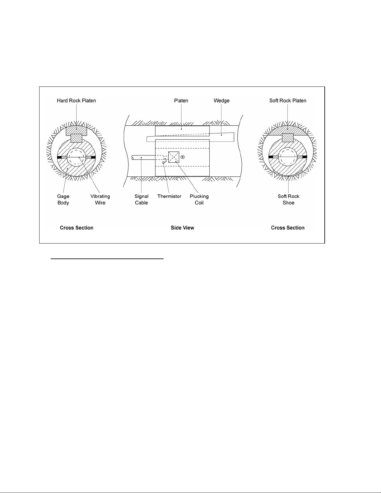
The gage wire in the Model 4300 Series stressmeters runs perpendicular to the direction in which the gage body is
loaded in an effort to minimize the effects of point loading, off center loading, etc. This gives the gage a very high
range and, since as the load increases the wire gets tighter, the wire never goes slack.
Gage installation is accomplished by driving a wedge between the gage body and the platen, which contacts the
borehole walls. Preloading to desired levels is accomplished by further driving of the wedge with the setting tool.
In soft rocks a soft rock platen and soft rock shoe are used to increase the area of contact.
The gage is constructed of corrosion resistant materials and should have an indefinite lifetime under even the
most severe conditions.
3. Installation______________________________________________________
3.1 Borehole Requirements
Stressmeters are designed to be used in smooth-walled diamond drill holes. Stressmeters can be installed in
percussively drilled holes and drag-bit drilled holes, provided that care is taken to get the proper hole diameter with a
smooth wall. If the walls are rough the gage response (calibration) can be radically affected.
The Model 4300EX Stressmeter is designed for use in EX diamond drill holes 38mm (1.5”), and the hole can
range in diameter from 37mm (1.45”) to 39mm (1.55”) when using the standard wedge and platen assembly.
The Model 4300BX Stressmeter is designed for use in BX diamond drill holes 60mm (2.36”), and the hole can
range in diameter from 58.5mm (2.30”) to 62mm (2.44”) when using the standard wedge and platen assembly.
The Model 4300NX Stressmeter is designed for use in NX diamond drill holes 76mm (2.98”), and the hole can
range in diameter from 74mm (2.91”) to 78mm (3.07”) when using the standard wedge and platen assembly.
Oversize platens are available for over-size boreholes (consult factory).
After drilling, the hole should be thoroughly cleaned by washing out with water or blowing out with compressed
air. The borehole diameter should then be checked with the GO-NO-GO gages supplied with the installation tool.
If the borehole checks out the installation can proceed.
3.2 Preliminary Checks
Upon receipt of the stressmeter the zero reading should be checked and noted along with the temperature if a
thermistor is included in the gage. Gage connections are normally red to red and black to black, although with the
GK-401 Readout Box these can be reversed without changing the readings. Zero readings at the site should
coincide with the factory readings within a few digits after corrections for temperature are made.
3.3 Attaching the Wedge/Platen Assembly

4
The wedge/platen assemblies are shipped separately. They are held together by a nylon screw and nut. Remove
the nut and then use the nylon screw to attach the wedge/platen assembly to the Stressmeter Body. Orient the
wedge so that the narrow end is facing in the same direction as the cable, (see Figure 2). Tighten the nylon screw
into the threaded hole in the body. Do not over-tighten – the screw is made of nylon so that it can be sheared
more easily. (Note: The BX size stressmeter and the NX size stress meter both use the same wedge. However,
there are two holes in the wedge. The one nearest the tip is for the BX size, the one farthest from the tip is for the
NX size).
3.4 Setting the Stressmeter (Recoverable Type)
Mount the stressmeter on the setting tool by pushing the nylon threaded pieces into the matching holes in the
setting tool head. Feed the gage leads through the slot in the setting head. (See figure 2 on page 5).
Connect the first section of ¼” rod to the yoke attached to the thin end of the wedge. Note that the first section of
rod has one end with a ¼-20 Left Hand Thread on it. This will connect to the left-hand thread in the yoke.
Attach the first section of the ¾” positioning rod to the back of the setting tool head. Push the stressmeter into the
hole using the positioning rod. The buttons on the setting rod connectors indicated the orientation of the wedge/
platen assembly. Thus for making measurements in a vertical direction keep the buttons to the top of the rod, etc.
As the ¾” positioning rod is pushed into the hole, add new sections of both ¾” and ¼” rod until the desired depth
has been reached. It is advisable to wear gloves during this procedure to protect the thumbwhile depressing
the buttons on the ¾ inch rods. Now slide the slide hammer over the last section of ¼” rod and then thread the anvil
block onto the outer end of the ¼” rod. Connect the GK-403 or GK-401 readout box to the lead wires and switch to
position “F” for EX size or “B” for BX and NX size. Take initial readings.
Figure 2. Vibrating Wire Stressmeter installation tool assembly.
Holding the positioning rod firmly at its correct depth and orientation, slide the slide hammer back up the ¼” rod,
then side it quickly back to the anvil striking it a sharp firm blow. This will shear the rivet holding the wedge to

5
the platen and will pull the wedge into the platen thereby expanding it against the wall of the borehole.
After the first blow, take another reading on the GK-403 or GK-401 and observe the change in reading. The
recommended preloads are as follows: for the EX size a reading change of 2000 digits on channel F, for the BX
size a reading change of 400 digits on channel B, for the NX size a reading change of 300 digits on channel B.
Use as many blows of the hammer as is necessary to achieve this reading. When the reading has been achieved,
disconnect the ¼” rod from the wedge yoke by turning clockwise (remember, left hand thread). Remove the ¼”
rod from the hole, then disengage the setting tool from the stressmeter by pulling on it.
For multiple installation of gages in a single hole, route the lead wires from deeper gages in the recess in the side
of the setting tool head. Maintain tension on these wires, as subsequent gages are pushed into the hole.
If necessary, after setting the gages and obtaining the final readings, push the leads back into the borehole and
seal the borehole using an expandable rockbolt anchor or a short bolt. This will discourage vandalism if this is a
problem.
Note that the stressmeter initial readings will probably diminish slightly over the first day or two as the
stressmeter beds firmly into place.
3.5 Recovering the Stressmeter
After tests, the stressmeter can be removed from the borehole by using the setting tool. Only the larger setting
rods are required along with the setting tool head, which is used to strike the outer tip of the wedge. This will
drive the wedge out from under the platen and allow the stressmeter to be pulled from the hole using the electrical
cable. Make sure that the setting head is twisted so that the flat part of the front face lies opposite the wedge. The
entire stressmeter can sometimes be recovered in this way i.e., the wedge, platen and stressmeter body. To reuse
these components will require a new nylon screw. (A few spare nylon screws are included in each shipment).
However, there is a good chance that the wedge and platen may dislodge in the borehole and be lost so it will be
advisable to carry spares of these also. (Note: The BX size stressmeter and the NX size stress meter both use the
same wedge. However, there are two holes in the wedge. The one nearest the tip is for the BX size, the one
farthest from the tip is for the NX size).
3.6 Splicing and Junction Boxes
Because vibrating wire readout is frequency rather than current or voltage, slight variations in cable resistance
have no ill effect on gage readings, and therefore splicing of cables presents no problem for installations and, in
many cases, can make the job easier.Splicing boxes allow for the use of multiconductor cables and enable the
gages to be set with a minimum of cable exposed in working areas.When properly made, splices are equal to the
cable itself in strength and electrical properties.Terminal boxes with switches or plug-in connections are available
for termination of multiple lead wires at a single readout location.Splicing materials, junction and splicing boxes
and terminal boxes, along with instructions, are available from Geokon.

6
4. Taking Readings ________________________________________________
4.1 Operation of the GK-403 or GK-401 Readout Box
The GK-403 or GK-401 Readout Box provides the necessary excitation and signal conditioning for the Model
4300 Series Stressmeters. To take readings, the box is connected to the gage by a jumper with either clip leads or,
in the case of a terminal station, with a connector.
1. Turn the display selector to position “F” for EX size or position “B” for BX and NX sizes.
2. Turn the unit on and a reading will appear in the front display window. The last digit may fluctuate by several
digits and this is explained below.
3. Zeros in the display indicate either a faulty connector, a damaged gage or high levels of electrical noise.
Connect the ground lead to the cable shield (in this last case) and if the signal does not appear, trouble
shooting is required (see Section 6).
4. The unit will automatically turn off after approximately 4 minutes to conserve power.
As noted above, the last digit in the display will very often fluctuate by several digits, and this should not be seen as
abnormal operation. In the case of the stressmeter, the vibrating wire is very short and the signals are not as pure as
those of other gages. This, coupled with the fact that we are presenting frequency squared, causes some instability,
which shows up in the least significant digit. This is not to say that the readings are not accurate; it simply means that
the period of vibration changes very slightly from one pluck to the next. In most cases the displayed numbers should
be rounded to the next least significant digit. For very stable stressmeters the last digit can give very valuable
information on very small stress changes, and for that reason the numbers are not rounded off electronically.
4.2 Operation of the GK404 Readout Box
The GK404 is a palm sized readout box which diplays the Vibrating wire value and the temperature in degrees
centigrade.
The GK-404 Vibrating Wire Readout arrives with a patch cord for connecting to the vibrating wire gages. One
end will consist of a 5-pin plug for connecting to the respective socket on the bottom of the GK-404 enclosure.
The other end will consist of 5 leads terminated with alligator clips. Note the colors of the alligator clips are red,
black, green, white and blue. The colors represent the positive vibrating wire gage lead (red), negative vibrating
wire gage lead (black), positive thermistor lead (green), negative thermistor lead (white) and transducer cable
drain wire (blue). The clips should be connected to their respectively colored leads from the vibrating wire gage
cable.
For EX size use the POS (Position) button to select position Fand the MODE button to select Dg (digits).
For BX and NX sizes use the POS (Position) button to select position Band the MODE button to select Dg
(digits).
Other functions can be selected as described in the GK404 Manual.

7
The GK-404 will continue to take measurements and display the readings until the OFF button is pushed, or if
enabled, when the automatic Power-Off timer shuts the GK-404 off.
The GK-404 continuously monitors the status of the (2) 1.5V AA cells, and when their combined voltage drops to
2V, the message Batteries Low is displayed on the screen. A fresh set of 1.5V AA batteries should be installed at
this point
5. Data Reduction _________________________________________________
The GK-403 or Gk-401 Readout excites the gage and measures the period of 255 cycles (or less) of gage
vibration, using a 6.144 MHz quartz oscillator, and displays the period to a resolution of 0.1 microseconds in
position “A”. Positions “F” and “B” are used for stressmeters, the processor converts the period readings to units
of frequency squared which is proportional to wire strain, gage deflection and applied stress.A reading of 10,000
on channel “F” corresponds to a period of 316.2 microseconds on channel “A”.
To obtain the change in stress at any given time the following equation applies:
σ= (R1 – R0) G, where
σ= stress in psi
R0= initial reading at zero stress (“B” or “F”, GK-401 or GK-403)
R1= reading at subsequent stress (“B” or “F”, GK-401 or GK-403)
G= sensitivity factor taken from Fig 3, 4 or 5
For example:
EX BX NX
Readout initial display = 10,000
Subsequent display = 12,000
Readout initial display = 4,000
Subsequent display = 5,000
Readout initial display = 2,500
Subsequent display = 3,000
σ= (R1– R0) G σ= (R1– R0) G σ= (R1– R0) G
σ= (12,000 – 10,000) 0.50 σ= (5,000 – 4,000) 2.5 σ= (3,000 – 2,500) 6.0
σ= 1,000 psi σ= 2500 psi σ= 3,000 psi
5.1 Gage Sensitivity Factors
Figures 3, 4 or 5 are used for determining the stress sensitivity or gage factor for rocks of different moduli.
Sensitivity factors are based on experimental data conducted on rock samples and can only serve as a guide.
For more accurate determinations of stress sensitivity, calibrations must be performed in samples of the rock
being monitored.

8
Figure 3. Model 4300EX Vibrating Wire Sressmeter Sensitivuty Factor VS. Rock Modulus
Figure 4. Model 4300BX Vibrating Wire Sressmeter Sensitivuty Factor VS. Rock Modulus

9
Figure 5. Model 4300NX Vibrating Wire Sressmeter Sensitivity Factor vs. Rock Modulus
5.2 Corrections for Temperature Changes
Because of the materials used in construction of the stressmeter the device is affected by changes in ambient
temperature. Since these gages are normally installed underground in constant temperature environments
corrections are not normally applied.
However, corrections can be made and transducers can be equipped with thermistors for temperature
measurement. The temperature correction factor for the gage is 2 readout box units/°C, indicating as apparent
decrease in rock stress for a temperature rise.
Stress correction for temperature is:
σT= (R1– R0) G + (T1– T0) 2G, where
σT= the stress change corrected for temperature
R
0= initial reading
R
1= subsequent reading
T
0= initial temperature °C
T
1= subsequent temperature °C
G = sensitivity factor

10
It should be noted that this temperature correction factor is for a gage in a free field with no restraints. In a field
condition where the gage is firmly placed in a borehole the gage temperature sensitivity is also dependent on the
gage/rock interactions, and these relationships are very complex and beyond the scope of this manual. Calibration
would be required for accurate determination of the thermal characteristics of the gage.
5.3 Environmental Factors
Since the purpose of the stressmeter installation is to monitor site conditions, factors that may affect these
conditions should always be observed and recorded. Seemingly minor effects may have a real influence on the
behavior of the structure being monitored and may give an early indication of potential problems. Some of these
factors include, but are not limited to: blasting, rainfall, tidal levels, excavation and fill levels and sequences,
traffic, temperature and barometric changes, changes in personnel, nearby construction activities, seasonal
changes, etc.
6.Trouble Shooting ________________________________________________
Maintenance and trouble shooting of vibrating wire stressmeters is confined to periodic checks of cable
connections and maintenance of terminals. The transducers themselves are sealed and cannot be opened for
inspection. The setting rods should be kept clean and the button mechanisms kept lightly oiled.
If a unit fails to read, the following steps should be taken:
1. Check the coil resistance. Nominal coil resistance is 90 Ω±5 for EX; 180 Ω±5 for BX and NX, plus cable
resistance (22 gage copper = approximately 20 Ωper 1000 feet).
a. If the resistance is high or infinite a cut cable must be suspected.
b. If the resistance is low or near zero a short must be suspected.
c. If resistances are within the nominal range and no reading is obtained, the transducer is suspect and the
factory should be consulted.
d. If all resistances are within nominal and no readings are obtainable on any transducer, the readout is
suspect and the factory should be consulted.
2. If cuts or shorts are located, the cable may be spliced in accordance with recommended procedures.
3. If readings are unstable try connecting the ground clip on the readout box to the cable shield.

11
Table 1: Thermistors ______________________________________________
Thermistor Linearization using Steinhart and Hart Log Equation
Tech Memo 91-03 Doc Rev 6-94, Geokon, Inc.
Thermistor Type: YSI 44005, Dale #1C3001-B3, Alpha #13A3001-B3
Basic Equation:
TA B LnR C LnR
=
++
−
1273 2
3
()() .
where: T =Temperature in °C
LnR =Natural Log of Thermistor Resistance
A =1.4051 ×10⁻³
B =2.369 ×10⁻⁴
C =1.019 ×10⁻⁷
Note: Coefficients calculated over -50
°
to +150
°
C. span.
Resistance versus Temperature Table
Ohms Temp Ohms Temp Ohms Temp Ohms Temp Ohms Temp
201.1K -50 16.60K -10 2417 +30 525.4 +70 153.2 +110
187.3K -49 15.72K -9 2317 31 507.8 71 149.0 111
174.5K -48 14.90K -8 2221 32 490.9 72 145.0 112
162.7K -47 14.12K -7 2130 33 474.7 73 141.1 113
151.7K -46 13.39K -6 2042 34 459.0 74 137.2 114
141.6K -45 12.70K -5 1959 35 444.0 75 133.6 115
132.2K -44 12.05K -4 1880 36 429.5 76 130.0 116
123.5K -43 11.44K -3 1805 37 415.6 77 126.5 117
115.4K -42 10.86K -2 1733 38 402.2 78 123.2 118
107.9K -41 10.31K -1 1664 39 389.3 79 119.9 119
101.0K -40 9796 0 1598 40 376.9 80 116.8 120
94.48K -39 9310 +1 1535 41 364.9 81 113.8 121
88.46K -38 8851 2 1475 42 353.4 82 110.8 122
82.87K -37 8417 3 1418 43 342.2 83 107.9 123
77.66K -36 8006 4 1363 44 331.5 84 105.2 124
72.81K -35 7618 5 1310 45 321.2 85 102.5 125
68.30K -34 7252 6 1260 46 311.3 86 99.9 126
64.09K -33 6905 7 1212 47 301.7 87 97.3 127
60.17K -32 6576 8 1167 48 292.4 88 94.9 128
56.51K -31 6265 9 1123 49 283.5 89 92.5 129
53.10K -30 5971 10 1081 50 274.9 90 90.2 130
49.91K -29 5692 11 1040 51 266.6 91 87.9 131
46.94K -28 5427 12 1002 52 258.6 92 85.7 132
44.16K -27 5177 13 965.0 53 250.9 93 83.6 133
41.56K -26 4939 14 929.6 54 243.4 94 81.6 134
39.13K -25 4714 15 895.8 55 236.2 95 79.6 135
36.86K -24 4500 16 863.3 56 229.3 96 77.6 136
34.73K -23 4297 17 832.2 57 222.6 97 75.8 137
32.74K -22 4105 18 802.3 58 216.1 98 73.9 138
30.87K -21 3922 19 773.7 59 209.8 99 72.2 139
29.13K -20 3748 20 746.3 60 203.8 100 70.4 140
27.49K -19 3583 21 719.9 61 197.9 101 68.8 141
25.95K -18 3426 22 694.7 62 192.2 102 67.1 142
24.51K -17 3277 23 670.4 63 186.8 103 65.5 143
23.16K -16 3135 24 647.1 64 181.5 104 64.0 144
21.89K -15 3000 25 624.7 65 176.4 105 62.5 145
20.70K -14 2872 26 603.3 66 171.4 106 61.1 146
19.58K -13 2750 27 582.6 67 166.7 107 59.6 147
18.52K -12 2633 28 562.8 68 162.0 108 58.3 148
17.53K -11 2523 29 543.7 69 157.6 109 56.8 149
55.6 150

12
Appendix 1: Biaxial Stress Changes ______________________________
The relationship between the radial deformation of a borehole, U, and two principle stresses in the plane of a
borehole has been given by Hast (1958) and Merrill and Peterson (1961).
For Plane Stress:
U = d/Er[(σ1+ σ2) + 2 (σ1- σ2) cos 2 θ]
Where: σ1and σ2are the principle stresses in the plane of the borehole.
θis the angle measured counterclockwise from the direction of σ1.
dis the diameter of the borehole.
Eris the Youngs modulus of the rock
If we assume that the stress measured across the stressmeter is proportional to the radial deformation that would
have occurred in this direction if the stressmeter had not been there, then the term d/Ercan be replaced by one
reflecting the relationship between the rock modulus and the gage modulus. Hast (1958) has shown this to be
applicable for a uniaxial stressmeter. For the measurement of stress σRin any direction θthe following applies:
σR= 1/3 (σ1+ σ2) + 2/3 (σ1- σ2) cos 2 θ
(θmeasured counterclockwise from σ1)
Using this relationship and three uniaxial stress change measurements at 45°to each other, the secondary
principle stresses σ1and σ2and the angle θare given by:
σ1= 3/2 a + ¾ b
σ2= 3/2 a – ¾ b
θ= 1/2 sin-1 ((a – σ45)/b)
where: a= σ0+ σ90 /2
b= [(σ45 – a)2+(σ0– a)2]1/2
To determine the θangles, you have to determine what quadrant the angle lies in. The inequalities to do this are
as follows:
If σ45≤a and σ0≥90, then 0≤θ≥45°
If σ45≤a and σ0≤. 90, then 45°≤θ≤90°
If σ45≥a and σ0≤90, then 90°≤θ≤135°
If σ45≥a and σ0≥90, then 135°≤θ≤180°
Note: θis measured clockwise for σ0(this is same as counter-clockwise for σ1).

13
Example:
Three gages are set in borehole. The first is at 0°(σ0), the second at 45°(σ45) and the third at 90°(σ90), measured
counter-clockwise from 0. The uniaxial stress changes for each gage are determined by the reading change times
the calibration factor.
Substitute the constants into the equations to obtain the magnitude of the changes of the two secondary principal
stresses, σ1relative to 0°.
Stress Changes: Gage 1, σ0= 600 psi
Gage 2 σ45 = 800 psi
Gage 3 σ90 = 300 psi
Calculate the values for constants, a and b:
a = σ0+ σ90/2 = 600 + 300/2 = 450
b = [(σ45 – a)2+ (σ0– a)2]1/2 = [(800-450)2+ (600-450)2]1/2 = 380.79
σ1= 3/2a + 3/4b = 3 x 450/2 + 3 x 380.79/4 = 960.59 psi
σ2= 3/2a – 3/4b = 3 x 450/2 – 3 x 380.79/4 = 389.41 psi
sin 2θ= -0.92
θ= 33.40°
σ1Direction: since σ45 > a and σ0> σ90, then 135 < θ< 180°.Therefore, θ= 180 – 33.40 = 146.6°.This is
measured clockwise from σ0.
References ________________________________________________________
Hast, N.; THE MEASUREMENT OF ROCK PRESSURE IN MINES;
Sveriges Geologiska Undersokning, Arsbok 52, Series C, 3. 1958.
Merrill, R.H. and Peterson, J.R.; DEFORMATION OF A BORE HOLE IN ROCK;
U.S. Bureau of Mines, RI 5881.
Table of contents
Other Geokon Measuring Instrument manuals

Geokon
Geokon 4910 User manual

Geokon
Geokon 4425 User manual

Geokon
Geokon 4430 User manual

Geokon
Geokon 4500MLP User manual

Geokon
Geokon 4500HT User manual

Geokon
Geokon 4420 User manual

Geokon
Geokon 4430 User manual

Geokon
Geokon 4500HT User manual

Geokon
Geokon 4300 Series User manual

Geokon
Geokon 4410 User manual
Popular Measuring Instrument manuals by other brands

Fidelity Electronics
Fidelity Electronics 19eA Operation manual

Badger Meter
Badger Meter Impeller 228PV150U Series user manual

IFM
IFM Efector 300 SL5204 installation instructions

DeNovix
DeNovix DS-11 Series user guide

Endress+Hauser
Endress+Hauser Stamolys CA71CODcr operating instructions

FuelTech
FuelTech FT INJECTOR 170 LB/H owner's manual