www.gerardi.it Pag. 2
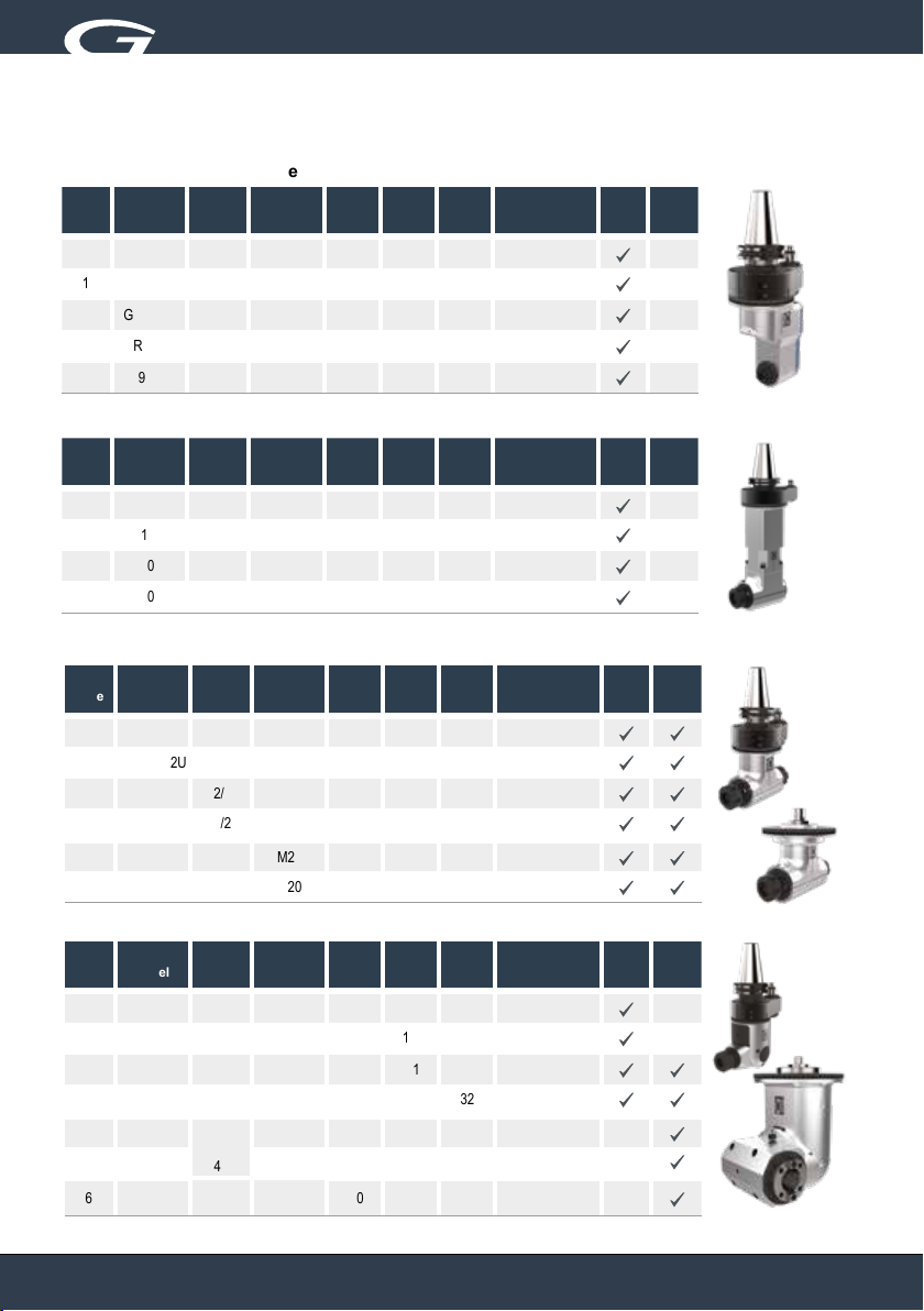
Angle heads
Classic line
Introduzione
Introduction
CARATTERISTICHE TECNICHE PRINCIPALI:
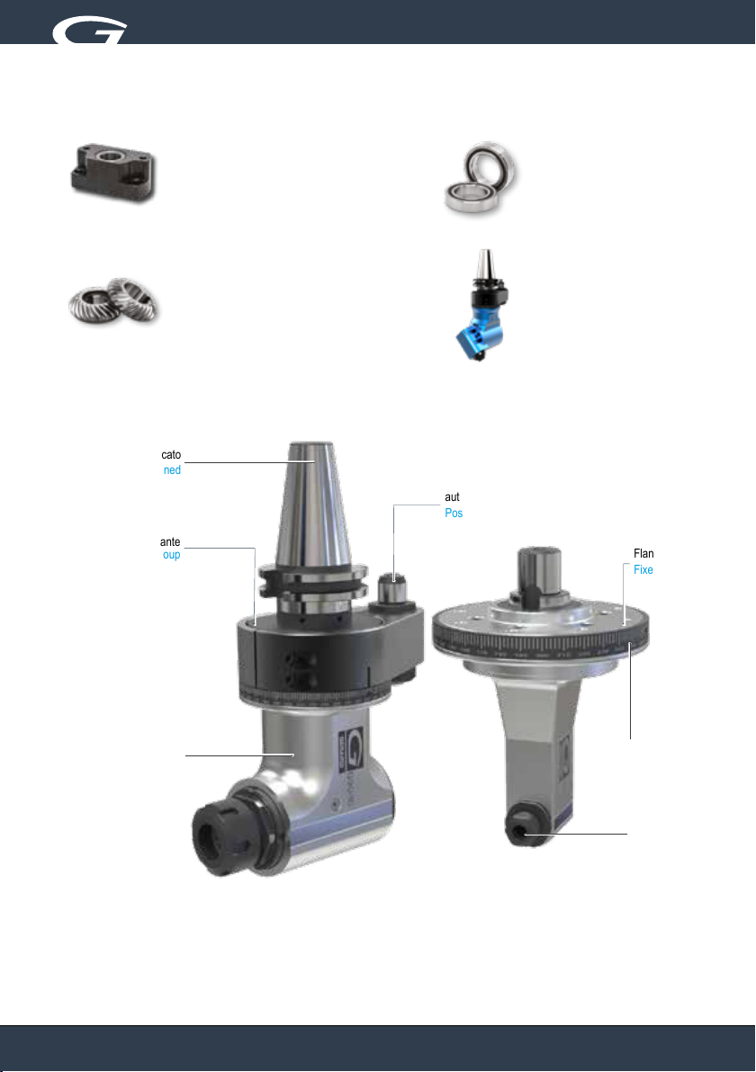
1- Corpo in acciaio sabbiato e cromato ad alta resistenza
2- Albero con cono di attacco integrale (cementato, temprato e retticato) per garantire la massima rigidità
3- Ciascun albero di trasmissione è supportato da almeno una coppia di cuscinetti a contatto obliquo, precaricati in classe di precisione
ABEC 9 e lubricati con grasso a vita.
4- Ingranaggi conici spiroidali in materiale ad alta resistenza, retticati per garantire minore riscaldamento e rumorosità anche ad elevato
numero di giri. Calcolo computerizzato della coppia conica degli ingranaggi (gleason): più denti in presa, più coppia in uscita, maggior
numero di ore di lavorazione, rumorosità quasi assente.
5- Pesi e ingombri ridotti rispetto ai modelli corrispondenti della linea Evolution.
6- Doppia tenuta anteriore (labirinto + tenuta).
7- Adduzione refrigerante esterno tramite perno e pressurizzazione interna compresa nel prezzo
8- Opzione adduzione refrigerante interno attraverso l’utensile:
- 10 bar tramite distributore rotante
- Da 30 a 70 bar tramite mandrino macchina, rotazione a secco non possibile
- Ghiere speciali ReCool per ottenere il passaggio refrigerante tramite utensile anche su teste che non prevedono questa opzione.
9- Alta velocità no a 10.000 giri.
10- Compatibilità con le teste da sempre installate (perno anti-rotazione e stop block).
11- 100% Made in Italy, le teste angolari Gerardi Classic Line sono progettate ed interamente realizzate in Italia e sono coperte da 1 anno
di garanzia.
MAIN TECHNICAL FEATURES:
1- Minimum thermal expansion and high corrosion resistant treated steel body
2- Main shaft is one solid piece with the drive input taper, case hardened and ground, to ensure maximum rigidity
3- Shafts supported by sets of super precision pre-loaded angular contact bearings with Long Life grease lubrication and ABEC 9
accuracy rating.
4- Ground spiral bevel gears in the highest performance materials able to guaranteed less warming and noise and the highest Rpm.
Computerized computation of the data of the set gears more than one tooth working during mesch, more power transmitted, longer
gear life, almost no noise
5- New types of longer angular heads with reduced weights and owerall dimensions
6- Double seals on the front (mechanical seal + gasket)
7- External coolant through the pin and internal air pressure included as a standard option.
8- Internal coolant feed through the tool options:
- 10 bar through rotating distributor
- From 30 to 70 bar through machine spindle, dry running not possible
- Special ReCool nuts to get the internal coolant through the tool even on angle heads that aren’t tted for this option.
9- High speed until 10.000 rpm
10- 100% compatibility with heads installed during the last 40 years (anti-rotation/arrester pin and stop block dimensions)
11- GERARDI Classic angle heads have been designed and are manufactured in Italy. They are covered by 1 year warranty.
Testa Angolare linea CLASSIC
Grazie per aver deciso di acquistare una testa ad angolo GERARDI SpA della serie CLASSIC.
Queste istruzioni per l'uso e la manutenzione hanno lo scopo di aiutarVi a prendere condenza con la Vostra testa ad angolo.
Vi consigliamo di leggerle e di conservarle per una successiva consultazione. Per le teste ad angolo di nostra costruzione Vi diamo
un'assoluta garanzia riguardo alla selezione dei materiali, precisione delle lavorazioni e dimensionamento oltre alla capacità richiesta
per una maggiore resistenza delle parti sollecitate.
Angle Head CLASSIC line
Congratulations for having chosen an CLASSIC LINE GERARDI SpA angle head the aim of these operating instructions is to help you
to become acquainted with your angle head unit.
We advise you to read them and keep them for future reference.
Our angle head are fully guaranteed in terms of selected materials , tolerances and sizing as well as high standards for the greater
strength of parts under stress.