FAAC 950 BM User manual

950BM
950BM
para la naturaleza
100% papel reciclado
ist umweltfreundlich
100% Altpapier
pour la nature
papier recyclé 100%
for nature
recycled paper 100%
carta riciclata 100%
per la natura

Fig. 2a
Fig. 2b Fig.3
1
122
3
3
1
2
4
5Fig.4 Fig. 4b
Fig. 4a
6

Fig.5
Fig.6

Quota con albero standard.
Nel caso fosse necessario aumentare
la distanza tra l’operatore ed il
braccio, utilizzare le prolunghe
modulari opzionali.
Ciacuna prolunga aumenta il valore
di altezza standard di 30 mm. E’
suggeribile non montare più di 2
prolunghe .
(*) Distance with standard extension.
If a greater distance between the
operator and the arm is required,
add the optional modular
extensions.
Each modular extension increases
the standard height of 30 mm. It’s
advisable not to place more then
2 extensions.
(*) Cote avec arbre standard.
Dans le cas d’installation
nécessitant une plus grande
distance entre l’opérateur et le
bras, utiliser les rallonges
modulaires en option.
Chaque rallonge augmente la
hauteur standard de 30 mm. Il est
conseillé de ne pas monter plus
de 2 rallonges.
(*)
(*) Cota con eje estándar.
Si fuera necesario aumentar la
distancia entre el actuador y el
brazo, utilizar las prolongaciónes
modulares opcionales.
Cada prolungación aumenta la
altura del eje de 30 mm. Se
recomanda de no instalar mas de
2 prolongaciónes modulares.
(*)
Quote in mm · Dimensions in mm · Cotes en mm · Maßangaben in mm · Cotas en mm
Quota con albero standard.
Nel caso fosse necessario aumentare
la distanza tra l’operatore ed il
braccio, utilizzare le prolunghe
modulari opzionali.
Ciacuna prolunga aumenta il valore
di altezza standard di 30 mm. E’
suggeribile non montare più di 2
prolunghe .
Tav.A: MONTAGGIO SULL’ARCHITRAVE (BRACCIO ARTICOLATO A SPINGERE) · TABLE A: LINTEL MOUNTING (PUSHING ARTICULATED ARM)
SCHÉMA A: MONTAGE SUR LE LINTEAU (BRAS ARTICULÉ Á POUSSER) · ÜBERSICHT A: STURZEINBAU (DRÜCK-GELENKARM)
LÁM. A: MONTAJE EN EL DINTEL (BRAZO ARTICULADO DE EMPUJE)
Piano di foratura · Drilling template · Schéma de perçage · Bohrbild · Plano de perforación

Quota con albero standard.
Nel caso fosse necessario aumentare
la distanza tra l’operatore ed il
braccio, utilizzare le prolunghe
modulari opzionali.
Ciacuna prolunga aumenta il valore
di altezza standard di 30 mm. E’
suggeribile non montare più di 2
prolunghe .
(*) Distance with standard extension.
If a greater distance between the
operator and the arm is required,
add the optional modular
extensions.
Each modular extension increases
the standard height of 30 mm. It’s
advisable not to place more then
2 extensions.
(*) Cote avec arbre standard.
Dans le cas d’installation
nécessitant une plus grande
distance entre l’opérateur et le
bras, utiliser les rallonges
modulaires en option.
Chaque rallonge augmente la
hauteur standard de 30 mm. Il est
conseillé de ne pas monter plus
de 2 rallonges.
(*)
(*) Cota con eje estándar.
Si fuera necesario aumentar la
distancia entre el actuador y el
brazo, utilizar las prolongaciónes
modulares opcionales.
Cada prolungación aumenta la
altura del eje de 30 mm. Se
recomanda de no instalar mas de
2 prolongaciónes modulares.
(*)
Quote in mm · Dimensions in mm · Cotes en mm · Maßangaben in mm · Cotas en mm
Quota con albero standard.
Nel caso fosse necessario aumentare
la distanza tra l’operatore ed il
braccio, utilizzare le prolunghe
modulari opzionali.
Ciacuna prolunga aumenta il valore
di altezza standard di 30 mm. E’
suggeribile non montare più di 2
prolunghe .
Tav.B : MONTAGGIO SULLA PORTA (BRACCIO ARTICOLATO A SPINGERE) · TABLE B: DOOR MOUNTING (PUSHING ARTICULATED ARM)
SCHÉMA B: MONTAGE SUR LA PORTE (BRAS ARTICULÉ Á POUSSER) · ÜBERSICHT B: TÜREINBAU (DRÜCK-GELENKARM)
LÁM. B: MONTAJE EN LA PUERTA (BRAZO ARTICULADO DE EMPUJE)
Piano di foratura · Drilling template · Schéma de perçage · Bohrbild · Plano de perforación

Quota con albero standard.
Nel caso fosse necessario aumentare
la distanza tra l’operatore ed il
braccio, utilizzare le prolunghe
modulari opzionali.
Ciacuna prolunga aumenta il valore
di altezza standard di 30 mm. E’
suggeribile non montare più di 2
prolunghe .
(*) Distance with standard extension.
If a greater distance between the
operator and the arm is required,
add the optional modular
extensions.
Each modular extension increases
the standard height of 30 mm. It’s
advisable not to place more then
2 extensions.
(*) Cote avec arbre standard.
Dans le cas d’installation
nécessitant une plus grande
distance entre l’opérateur et le
bras, utiliser les rallonges
modulaires en option.
Chaque rallonge augmente la
hauteur standard de 30 mm. Il est
conseillé de ne pas monter plus
de 2 rallonges.
(*)
(*) Cota con eje estándar.
Si fuera necesario aumentar la
distancia entre el actuador y el
brazo, utilizar las prolongaciónes
modulares opcionales.
Cada prolungación aumenta la
altura del eje de 30 mm. Se
recomanda de no instalar mas de
2 prolongaciónes modulares.
(*)
Quote in mm · Dimensions in mm · Cotes en mm · Maßangaben in mm · Cotas en mm
Quota con albero standard.
Nel caso fosse necessario aumentare
la distanza tra l’operatore ed il
braccio, utilizzare le prolunghe
modulari opzionali.
Ciacuna prolunga aumenta il valore
di altezza standard di 30 mm. E’
suggeribile non montare più di 2
prolunghe .
Tav.C
: MONTAGGIO SULL’ARCHITRAVE (BRACCIO A PATTINO L=330mm) · Table A: LINTEL MOUNTING (SLIDING ARM L=330mm)
Schéma A: MONTAGE SUL LE LINTEAU (BRAS Á PATIN L=330mm) · Übersicht A: STURZEINBAU (GLEITARM L=330mm)
Lám. A: MONTAJE EN EL DINTEL (
BRAZO CON PATÍN L=330mm)
Piano di foratura · Drilling template · Schéma de perçage · Bohrbild · Plano de perforación

Quota con albero standard.
Nel caso fosse necessario aumentare
la distanza tra l’operatore ed il
braccio, utilizzare le prolunghe
modulari opzionali.
Ciacuna prolunga aumenta il valore
di altezza standard di 30 mm. E’
suggeribile non montare più di 2
prolunghe .
(*) Distance with standard extension.
If a greater distance between the
operator and the arm is required,
add the optional modular
extensions.
Each modular extension increases
the standard height of 30 mm. It’s
advisable not to place more then
2 extensions.
(*) Cote avec arbre standard.
Dans le cas d’installation
nécessitant une plus grande
distance entre l’opérateur et le
bras, utiliser les rallonges
modulaires en option.
Chaque rallonge augmente la
hauteur standard de 30 mm. Il est
conseillé de ne pas monter plus
de 2 rallonges.
(*)
(*) Cota con eje estándar.
Si fuera necesario aumentar la
distancia entre el actuador y el
brazo, utilizar las prolongaciónes
modulares opcionales.
Cada prolungación aumenta la
altura del eje de 30 mm. Se
recomanda de no instalar mas de
2 prolongaciónes modulares.
(*)
Quote in mm · Dimensions in mm · Cotes en mm · Maßangaben in mm · Cotas en mm
Quota con albero standard.
Nel caso fosse necessario aumentare
la distanza tra l’operatore ed il
braccio, utilizzare le prolunghe
modulari opzionali.
Ciacuna prolunga aumenta il valore
di altezza standard di 30 mm. E’
suggeribile non montare più di 2
prolunghe .
Tav.D
: MONTAGGIO SULL’ARCHITRAVE (BRACCIO A PATTINO L=430mm) · Table A: LINTEL MOUNTING (SLIDING ARM L=430mm)
Schéma A: MONTAGE SUL LE LINTEAU (BRAS Á PATIN L=430mm) · Übersicht A: STURZEINBAU (GLEITARM L=430mm)
Lám. A: MONTAJE EN EL DINTEL (
BRAZO CON PATÍN L=430mm)
Piano di foratura · Drilling template · Schéma de perçage · Bohrbild · Plano de perforación

22
ENGLISHENGLISH
CE DECLARATION OF CONFORMITY FOR MACHINES
(DIRECTIVE 98/37/EC)
Manufacturer: FAAC S.p.A.
Address: Via Benini, 1
40069 - Zola Predosa
BOLOGNA-ITALY
Declares that: 950 BM automated system,
•is built to be integrated into a machine or to be assembled with other
machinery to create a machine under the provisions of Directive 98/37/EC;
•conforms to the essential safety requirements of the following EEC directives:
73/23 EEC and subsequent amendment 93/68/EEC.
89/336 EEC and subsequent amendment 92/31/EEC and 93/68/EEC
and also declares that the machinery must not be put into service until the
machine in which it will be integrated or of which it will become a component
has been identified and declared as conforming to the provisions of Directive
98/37/EC.
Bologna, 01 January 2003
The Managing
Director
A. Bassi

23
ENGLISH ENGLISH
FAAC 950 BM
Fig. 1
1 Cablehole
2 Support profile
3 950 I/O electronic control unit
4 Adjustment of internal
mechanicalstops.
5 Transmissionshaft coupling
6 Protectionfor drivesystem and
re-closurespring.
7 DC motor
8 950MPS programmingunit
9 Toroidal transformer
10 Mains powerterminal board.
11 Casing securingbracket
12 Earth lug
13 Power cable terminal
The 950 BM automated system for swing doors is an enbloc unit
consisting of an electromechanical device that allows door
opening to be controlled by means of a driving arm. The door is
re-closed by a spring system.
The operator can be installed either on the lintel or on the door
structure itself.
The ABS-plastic protective casing houses the electronic control
unit used to program and control the operation of the system.
In the event of a power failure the door can be pushed (or pulled)
open manually.
1. DESCRIPTION AND TECHNICAL CHARACTERISTICS
Table 1: Technical specifications of 950 BM Operator
Power supply 230 Vac (+6 -10%) - 50 (60) Hz
Absorbed power 100 W
Absorbed current 0,5 A
Electric motor 24 Vdc with encoder
Dimensions 530x105x160 mm (length x height x depth)
Weight 10 Kg
Operating ambient temperature - 20 + 55 °C
Protection class IP 23 (internal use only)
Dimensions and leaf max weight see Table 3 (paragraph 1.1)
Use frequency continuous
Operation in event of power failure Manual push/pull
opening
Configuration of driving arms • pushing articulated arm
(version for jamb depth 0 ¸250 mm)
• sliding arm (arm length 430 mm)
• sliding arm (arm length 330 mm )
Anti-crushing device standard
Opening angle see table 5-6
Opening speed 4 ¸10 s (adjustable)
Closing speed 4¸10 s (adjustable)
Table 2: Technical specifications of Control Board
950I/O and Control Board 950 MPS
Power supply 230 Vac (+6 -10%) - 50 (60 Hz)
Accessories power supply 24 Vdc / 500mA max
Electric lock power supply (N.O./N.C.) 24 Vdc / 500mA max
Standard operating functions (selector switch)
Open / Automatic / Manual
(Night)
Adjustable functions (trimmer) Opening speed - Closing speed
Pause time
Selectable functions (microswitches) Closing stroke -
Standard/slide initialisation procedure
Push and Go - Function selector switch (pos.”2”)
STOP safety device operation - RS232 port
Terminal board outputs Malfunction alarm signal -
Electric lock power supply (N.O./N.C) -
24 Vdc accessories power supply - Door status signal
Changeover relay controlled by Card Reader -
“Two-leaf door” signal - “Interlock” signal
Terminal board inputs Internal / external Commands -
Emergency Command - Key Command -
Card Reader Command - Fire-alarm Command
STOP Safety device - CLOSING Safety device
Rapid connectors KP-CONTROLLER (optional) -
Minidec, Decoder or RP cards connection -
Functions selector switch connection
1.1. APPLICATION LIMITS
Important:To ensure correct application of the FAAC 950 BM unit
the weight of the door must not exceed the value given in Table
3 referred to its length.
The maximum length of the leaf is 1400 mm.
The values of maximum weight vary according to the driving arm
used.
For each driving arm there is also a different maximum value for
the depth of the jamb (Table 4) beyond which it is not possible
to install the system correctly.
Table 3: Application limits of 950 BM automated system
Leaf length Max leaf weight (Kg) Max leaf weight (Kg) Max leaf weight (Kg)
(mm) Pushing articulated Sliding arm Sliding arm
arm L=330mm L=430mm
700 367 286 -
750 320 249 -
800 281 219 -
850 249 - 194
900 222 - 173
950 199 - 155
1000 180 - 140
1050 163 - 127
1100 149 - 116
1150 136 - 106
1200 125 - 97
1250 115 - 90
1300 107 - 83
1350 99 - 77
1400 92 - 71
Table 4: Max jamb depth
Pushing
articulated
arm
Sliding
arm
L=330
Sliding
arm
L=430
0 - 250 0 - 160 0 - 160
m m
1234
5
6
7
8
9
10
11
12
13

24
ENGLISHENGLISH
1.2 DOOR MAX OPENING ANGLE
According to the type of mounting and respecting the installation
dimensions shown in Tables A,B,C, or D, different door max.
opening angles can be obtained according to the lintel thickness.
Table 5 and 6 shows the maximum values of the opening angles
that can be obtained in the different configurations.
Tab.5: Door max opening angle with pushing articulated arm.
Type of installation Jamb depth (mm) Max opening angle
operator on lintel 0 100°
operator on lintel 125 110°
operator on lintel 250 125°
operator on door 0 100°
Tab.6: Door max opening angle with sliding arm.
Type of installation Jamb depth (mm) Max opening angle
operator on lintel 0 90°
arm L=430 mm
operator on lintel 160 105°
arm L=430 mm
operator on lintel 0 90°
arm L=330 mm
operator on lintel 160 90°
arm L=330 mm
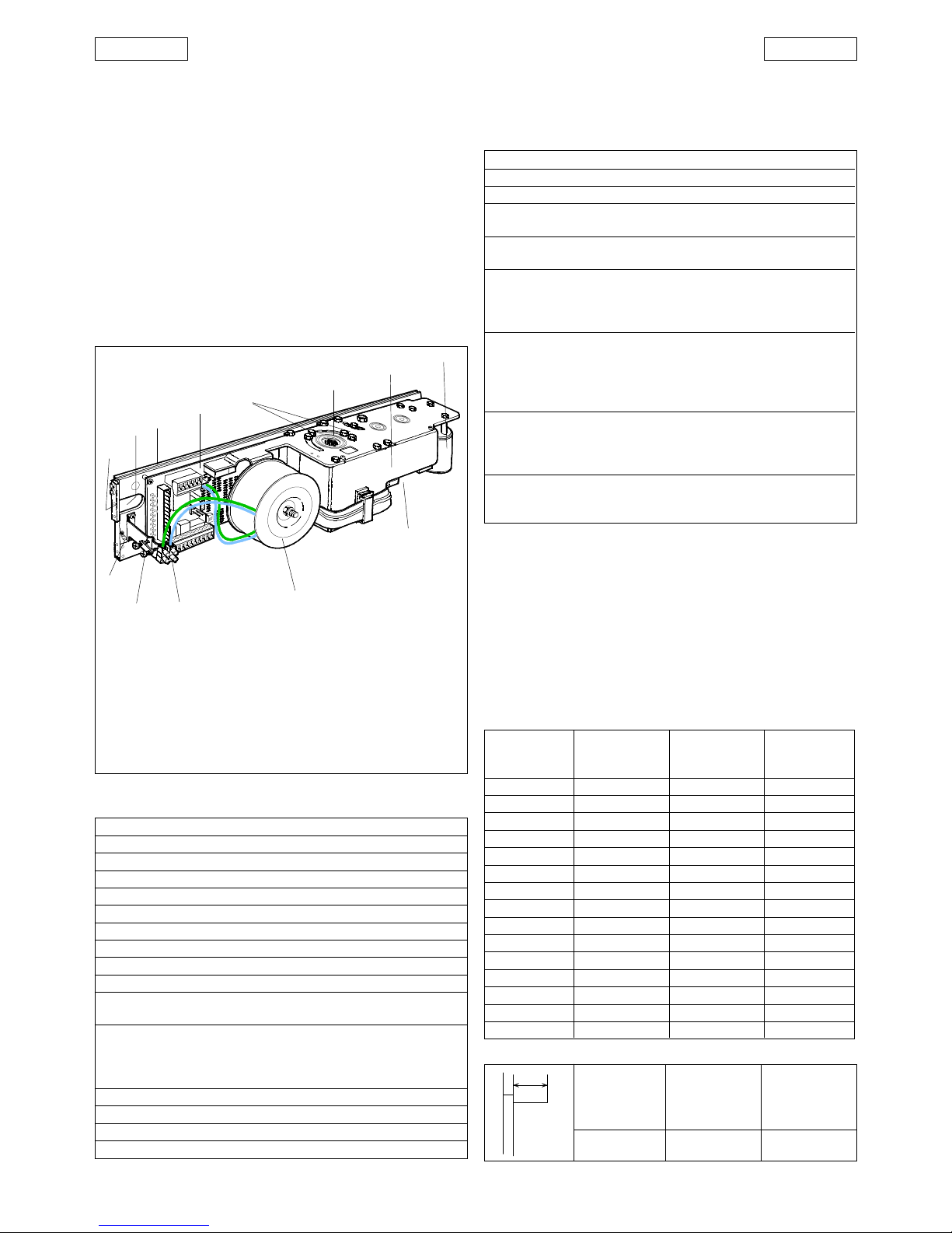
2. ELECTRICAL SETUP (fig. 2a Standard system)
950 BM operator
Microwave radar / Passive infrared sensor
T20E outdoor key-operated selector switch
(KEY command)
Emergency Closing/Opening pushbutton
KP-CONTROLLER programming unit (optional)
KP-CONTROLLER inhibition switch (optional)
24 Vdc electric lock
Junction box
If the operator is installed on the door, make the electrical
connections using a junction box and suitable commercially
available pipes/unions (fig. 2b).
Notes: 1) To lay electric cables, use suitable rigid and/or flexible
piping.
2) Always keep the low voltage accessory connection
cables separate from the 230 V power cables. To avoid
interference, use separate sheaths.
3. INSTALLATION
3.1. PRELIMINARY CHECKS
To ensure correct operation of the automated system the structure
of the existing door must meet the following requirements:
- length and weight as specified in Table 3 (paragraph 1.1.);
- max. jamb depth as specified in Table 4;
- robust and rigid structure of the leaf;
- good condition of the existing hinges;
- smooth, uniform movement of the leaf with no abnormal friction
during its entire travel;
- “neutral” position of the door during its entire travel. If the door
tends to close or open, check the alignment of the hinges.
- Presence of mechanical travel stops.
3.2. MOUNTING THE OPERATOR
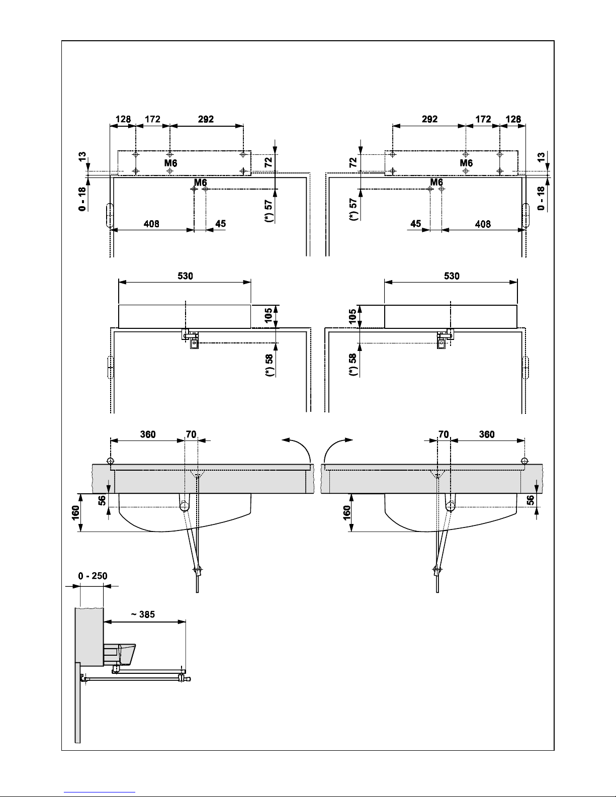
1) As regards the mounting position of the operator (on the lintel
or on the door) and the type of arm to use (pushing or sliding),
refer to the relevant mounting table and drill the holes
required to mount the operator and the pulling arm.
N.B.: The two intermediate operator fixing holes are not in a central
position (see Mounting tables). The holes are offset in order to
ensure that the operator is mounted with the correct direction of
rotation of the mechanism.
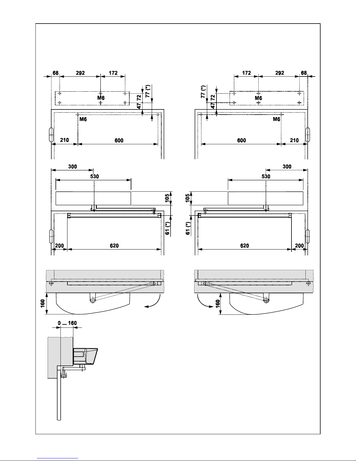
The mounting tables are the following:
Table A: LINTEL MOUNTING (PUSHING ARTICULATED ARM): Outward
opening.
Table B: DOOR MOUNTING (PUSHING ARTICULATED ARM): Inward
opening.
Table C:LINTEL MOUNTING (SLIDING ARM LENGTH 330mm): Inward
opening.
Table D: LINTEL MOUNTING (SLIDING ARM LENGTH 430mm):Inward
opening.
2) Mount the casing fixing brackets as shown in fig.3 according
to the type of mounting to be made. Tighten the screws (fig.3-
ref.1) and fit the screws (fig.3-ref2) without tightening them
completely.
3) Mount the operator using the six M6 screws and washers
provided.
Warning:
- The structure of the lintel (or the door) at the operator mounting
position must not exhibit any significant deformation.
- The operator must be mounted parallel to the floor.
N.B.: If the sliding arm is to be used, the driving arm must be
mounted before the operator is fixed on the lintel (see paragraph
3.3.2.).
3.3. MOUNTING THE DRIVING ARMS
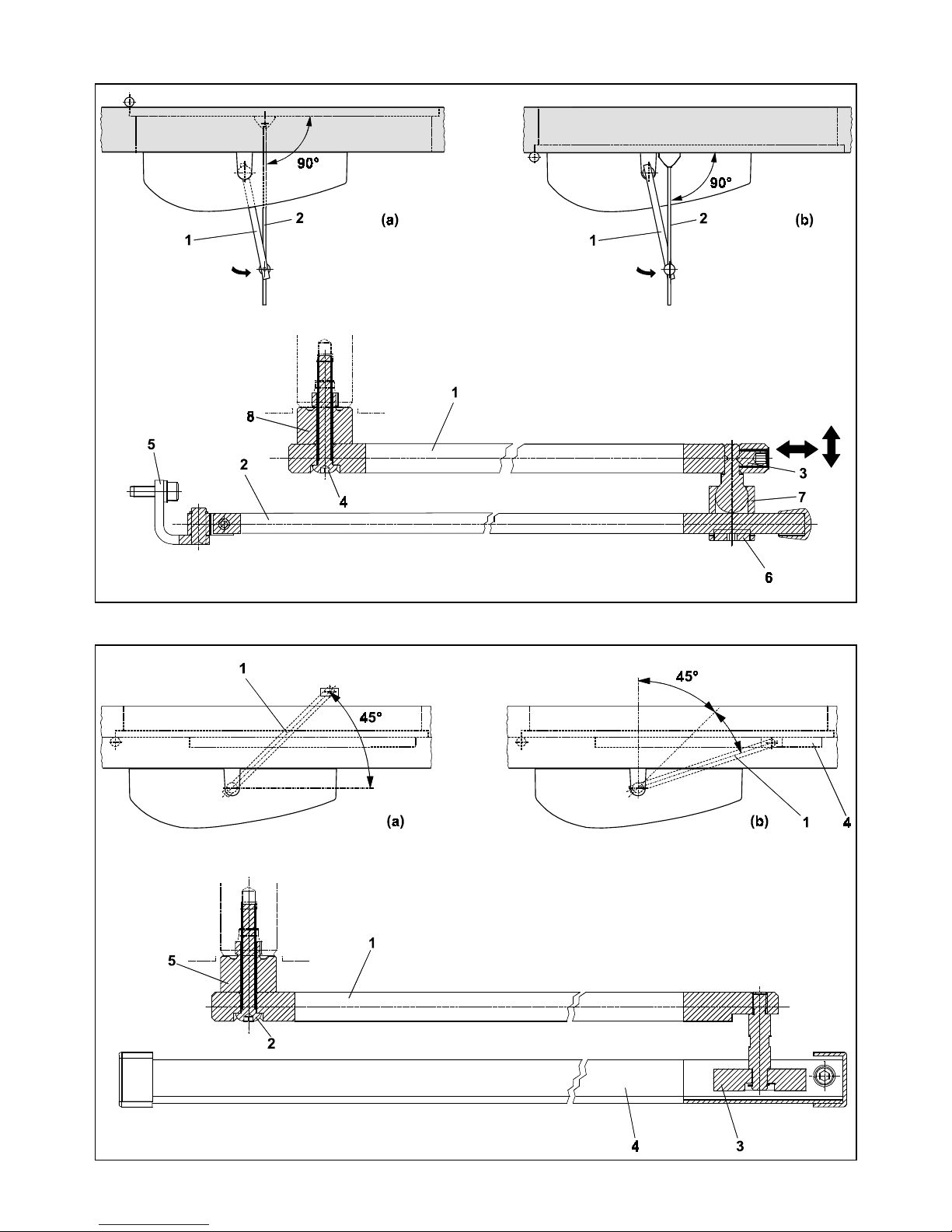
3.3.1. MOUNTING THE PUSHING ARTICULATED ARM (fig.5)
1) Close the door.
2) Free arms (1) and (2) by loosening the fixing dowel (3) as shown
in fig.5.
3) Fit arm (1) on the coupling of the operator transmission shaft
by means of the standard shaft (8) and the screw (4)
provided (fig.5). The arm must be mounted perpendicular to
the closed door.
Note: If a greater distance between the operator and the arm is
required, use the shaft modular extensions, available as
accessories, until the required distance is reached. (see Table A/
B).
4) Mount plate (5) of arm (2) on the door or the lintel using the
twoM6 screws andthe washersprovided (fig. 5).The installation
dimensions are given in Table A/B.
5) Slacken the fixing screw (6) and assemble the two arms by
tightening the dowel (3) (fig.5).
6) Turn arm (1) until arm (2) is perpendicular to the closed door
or the lintel as shown in fig. 5 (a-b), sliding the spacer (7) along
arm (2).
7) Tighten the fixing screw (6) between the two arms.
The length of arm (2) is given in the relevant mounting tables.
If necessary, cut off the section of the arm extending beyond
the articulation and then cover its end using the cap provided
(fig. 5).
8) Check manually that the door is free to open and close fully
and that it comes to rest against the mechanical stops. If the
door does not close correctly, adjust the return spring as
described in paragraph 9.
Important: The two driving arms must never touch.
Note: it is advisable to always adjust the operator internal
mechanical stops (fig.1 -ref 4), open/closed, so that they can be
activated when the leaf mechanical stops are reached.

25
ENGLISH ENGLISH
3.3.2. MOUNTING THE SLIDING ARM (fig.6)
1) Mount arm (1) on the operator transmission shaft by means
of the standard shaft (5) and the screw (2) provided (fig.6).
The arm must be fitted pointing 45° outwards as shown in fig.
6(a).
Note: If a larger distance is required between the operator and
the arm use the shaft modular extensions available as accessories,
until the required distance is reached (see Table C/D).
Warning: Mount arm (1) on the transmission shaft before fitting the
operator on the lintel (fig.6).
2) Insert the teflon slide (3) inside the sliding guide (4) (fig.6).
3) Pull arm (1) inwards manually as shown in fig. 6(b) and secure
the sliding guide (4) by means of two M6 screws on the closed
door as shown in Table C/D.
4) Check manually that the door is free to open and close fully
and comes to rest against the mechanical travel stops. If the
door does not close correctly, adjust the return spring as
described in paragraph 9.
4. START-UP
1) Make the electrical connections to the 950 I/O electronic
control unit as described in paragraph 6, and connect the
mains power supply to the specific terminal (fig.1-ref.10)
ensuring to crimp the earth wire to the lug (fig.1-ref.12)
screwed to the support profile (fig.1-ref.2). Then tighten the
terminal (fig.1-ref.13)
To gain access to the control unit, pass the cables through
the special conduit (fig.1-ref.1) or break the knockout areas
on the casing sides (fig.4-ref.6).
IMPORTANT: When mounting the “sliding” arm or for opening
angles greater than 90°, turn microswitch no. 2 to ON before
connecting power to the system.
2) Close the door.
3) Power up the operator.
4) Check that the green LEDs LD1 and LD3 on the board 950MPS
light up.
5) Check that the status signalling LEDs on the board 950I/O are
in the default status shown in Table 7 .
N.B.: The default status of the LEDs with the door closed at rest is
shown in bold type.
Table 7: Operation of the status signalling LEDs for 950 I/O board
LED ON OFF
LD1 Accessories power present Accessories power absent
LD2 Card Reader active Card Reader inactive
LD3 Internal sensor active Internal sensor inactive
LD4 External sensor active External sensor inactive
LD5 Emergency inactive Emergency active
LD6 STOP safety device inactive STOP safety device active
LD7 CL safety device inactive CL safety device active
LD8 Key active Key inactive
LD9 Fire-alarm active Fire-alarm active
6) Run a SET-UP cycle as indicated in paragraph 4.1.
4.1. SET UP PROCESS
Once the system is powered up, hold down SW1 button for at least
5 sec., until the LD2 red LED on the 950MPS board lights up. The LED
will start flashing to indicate that SET UP process is in progress.
During this process the following parameters are set:
- measuring the mass of the door;
- determining the travel stop positions;
The door opens at low speed, then closes half way before
switching back to opening.
Subsequent closure is performed by the return spring.
The process may be inhibited in any of the following conditions:
- function selector switch in the 2 (MANUAL/NIGHT) position or KP-
CONTROLLER programming unit in MANUAL or NIGHT position.
- incorrect connection of the accessories (electric lock, control/
safety devices);
- incorrect positioning of the programming unit microswitches.
Note: To repeat the initialisation procedure hold down the SW1
button for more than 5 seconds.
Check that door opens and closes correctly by sending an
opening command to one of the following inputs: Internal Sensor,
External Sensor or Key command. Set the trimmers (par.5.2) and
program the microswitches (par.5.4) according requirements.
5. 950MPS ELECTRONIC CONTROL UNIT
5.1 LAYOUT AND DESCRIPTION
MICROSWITCHES RS-232 CONNECTOR
ADJUSTING TRIMMER SIGNALLING LED
MOTOR
CONNECTOR
40VDC
CONNECTOR
Fig. 8

26
ENGLISHENGLISH
5.2. SETTING THE ADJUSTING TRIMMERS
The programming unit features trimmers (fig.8) which regulate the
following parameters:
Trimmer TR1 to set the opening speed.
Setting from 4 to 10 seconds.
Trimmer TR2 to set the closing speed.
Setting from 4 to 10 seconds.
Trimmer TR3 to set the pause time (AUTOMATIC logic).
Setting from 0 to 30 seconds.
5.3. SIGNALLING LEDs
LD1 Led = Green LED - electric motor power supply.
LD2 Led = Red LED - indicates SET-UP/Alarm.
LD3 Led = Green LED - 5V power supply.
5.4.2. MICROSWITCH No. 2 - SET-UP PROCESS
When mounting the “sliding” arm or for opening angles greater
than 90°, this microswitch has to be enabled.
OFF = Function DISABLED
ON = Function ENABLED
5.4.3. MICROSWITCH No. 3 - SELECTOR FUNCTION (“ 2 ” POSITION)
This function allows the operating function to be selected with the
selector switch in the “2” position.
OFF = MANUAL Function
ON = NIGHT Function
5.4.4. MICROSWITCH No. 4 - PUSH AND GO
When activated, this function enables the opening command to
be given by pushing the closed door manually. It is sufficient to
give the door an initial push/pull in the opening direction.
OFF = Function DISABLED
ON = Function ENABLED
WARNING: It is advisable not to enable this function if the door is
subject to strong wind, according to its structure and dimensions,
as this could activate the system's spontaneous opening or
motion reversing.
5.4.5 . MICROSWITCHES Nos. 5/6/8/9 - INACTIVE
5.4.6. MICROSWITCH No. 7 - STOP SAFETY DEVICE
It makes it possible to detect activation of the STOP safety device
during the entire door travel (COMPLETE) or to disable detection
beyond 70° opening (REDUCED).
OFF = COMPLETE Function
ON = REDUCED Function
When the STOP safety control is ensured by an active sensor fitted
on the leaf, if you enable the REDUCED function, the detection
of any obstacle (e.g. side wall) is prevented which would cause
interruption of the work cycle.
5.4.7 MICROSWITCH No. 10 - RS232 PORT
It makes it possible to enable the RS232 port connection to PC for
software update. In normal use conditions, the dip switch is in OFF
position.
OFF = Port DISABLED
ON = Port ENABLED
6. 950 I/O ELECTRONIC CONTROL UNIT
5.4. PROGRAMMING THE MICROSWITCHES (fig.9)
The programming unit has a series of microswitches which allow the
functionsshownto be selected.
The system is supplied with all the microswitches in the OFF position.
5.4.1. MICROSWITCH No. 1 - CLOSING STROKE
This function enables the closed position force to be increased by
further loading the transmission system after the door has reached
the mechanical closure stop.
It is advisable to use this function to assist activation of the electric
lock.
OFF = Function DISABLED
ON = Function ENABLED
MICROSWITCHES
1 2 3 4 5 6 7 8 9 10
OFF
ON Fig. 9
Fig. 10
6.1 LAYOUT AND DESCRIPTION

27
ENGLISH ENGLISH
Warning: Always disconnect the electric power supply before
carrying out any work on the control unit (connection,
maintenance).
DS1 No.2: Lock activation delay
OFF = DISABLED
ON = ENABLED
If this dip-switch is enabled, the door movement is delayed
by 500msec with respect to the electric lock command. If
disabled, delay is 200 msec.
No.1: Inactive
SW1 SET-UP pushbutton
Hold down the SET-UP button for 5 sec. to start the set-up
cycle.
FUSE F1 1AT/230Vac - 5x20
J1 CONNECTOR Transformer Secondary winding - fig. 10
J2 CONNECTOR
Rapid Connector of Manual/Night,Open,Automatic
function selector switch
J3 CONNECTOR KP-Controller Connection
1- 2 Connector of KP-Controller programming unit (optional) as
shown in fig. 24.
Use a 2 x 0.5 mm² shielded cable (“bus” communication) for
the connection. Respect the connection polarity as shown
in figure 24.
Important: Themaximum permissible lengthofthe connection
cable is 50 m.
To inhibit operation of the SD-KEEPER, make the jumper
between terminals of the LOCK switch (fig.24).
J4 TERMINAL BOARD Inputs Connection (figs. 11,12,16)
7- 8 GND
Accessories power supply Negative and contacts Common
9 +24Vdc
+24Vdc accessories power supply
10 Internal Command - N.O. Contact
Any pulse generator (pushbutton, sensor, etc.) which, by
closing a contact, commands door opening.
To install several pulse generators as Internal Command,
connect the N.O. contacts in parallel.
11 External Command - N.O. Contact
Any pulse generator (pushbutton, sensor, etc.) which, by
closing a contact, commands door opening.
To install several pulse generators as External Command,
connect the N.O. contacts in parallel.
12 Emergency Command - N.C. Contact
Any pulse generator (normally a pushbutton) which, by
opening a contact, commands an emergency closure of the
system. Alternatively this input can be used to command
emergency opening by programming the system in a suitable
manner using the KP-CONTROLLER programming unit (optio-
nal).
To install several emergency command devices, connect the
N.C. contacts in series.
N.B.: If emergency command devices are not connected,
jumper inputs 7and 12.
Attention: Using the KP-CONTROLLER programming unit, you
can change the type of contact from N.C. to N.O. contact.
13 CLOSURE Safety Command - N.C. Contact
Any device (safety sensor, photocell, etc.) which, by opening
a contact, has a safety effect on the closing movement of the
door.
The safety device causes an immediate reversing of the
closing movement of the door, but has no effect on the
opening movement of the door.
To install several CLOSURE safety devices, connect the N.C.
contacts in series.
N.B.: If CLOSURE safety devices are not installed, jumper inputs
7and 14.
14 STOP Safety Command - N.C. Contact
Any device (safety sensor, photocell, etc.) which, by opening
a contact, has a safety effect on the operating cycle. In
particular, this safety device interrupts the opening/closing
movement of the door.
When the safety device is disengaged, the door resumes its
opening/closing movement and continues to the end of the
cycle.
To install several STOP safety devices, connect the N.C.
contacts in series.
N.B.: If STOP safety devices are not installed, jumper inputs 7
and 13.
7 8 9 10 11 12 13 14 15 16 17 18 19
GND
GND
+ 24 Vdc
Internal Command
External Command
Closure Safety Command
STOP Safety Command
Emergency Command
Key Command
Fire-alarm Command
Card Reader Command
GND
GND
J4
Fig. 11
7 8 9 13 14 15
TX RX
PB SENSOR
+
-
C
+
+
-
-
C
J4
Fig. 12
7 8 9 10 11 12 13 14 15 16 17 18 19

28
ENGLISHENGLISH
15 KEY Command - N.O. Contact
Any pulse generator (pushbutton, sensor, etc.) which, by
closing a contact, commands door opening.
To install several pulse generators as Internal Command,
connect the N.O. contacts in parallel.
16 FIRE-ALARM Command - N.O. Contact
Any device (fire-alarm sensor, etc.) which, by closing a
contact, commands door closing.
Permanence of the closed contact, inhibits operation of any
other pulse generator.
To install several devices as FIRE-ALARM Command, connect
the N.O. contacts in parallel.
17 CARD READER Command - N.O. Contact
Any device (card reader, digital buttonboards, etc.) which,
by giving a 24Vdc pulse, commands the door opening and
the activation of the changeover relay (terminals 20/21/22,
J6 terminal board). The open pause time is fixed at 10 sec.
18 - 19 GND
Accessories power supply Negative and contacts Common
J5 TERMINAL BOARD Connection to relay Outputs (figs.
13,14, 15)
Description of the terminal board
1 Electric lock - Common
2 Electric lock - N.O. Contact (max. capacity 0.5 A/24 V)
(fig.13).
If no power is supplied the electric lock is active and therefore
guarantees closing mechanical locking.
In the NIGHT function the electric lock is active even if no
power is supplied. In the event of an opening command (Key
or EMERGENCY command), the electric lock is temporarily
powered to enable the door to be opened. In this case a
reverse stroke command is also given to enable the
mechanical release of the system.
7 8 9 10
1 2 3 4 5 6J5 J4
max 0.5A/24Vdc
1 2 3 4 5 6 7 8 9 10
J5 J4
max 0.5A/24Vdc
1 2 3 4 5 6
DOOR
OPEN
DOOR
CLOSED
COM.
max 0.5 A/24 Vdc
15 16 17 18 19
CARD READER - 24Vdc Signal
C. R. Comand
GND
+-
22 23 24 25 26
max 0.5 A/24 Vdc
ALARM Output
ALARM Output
+24 Vdc
GND
Fig. 13 Fig. 14
Fig. 15 Fig. 16
Fig. 17 Fig. 18 Fig. 19
J4
J5
J6 J6
J6 25 26 27 28
Interlock Signal
2 Leaf Signal
20 21 22
Com. changeover Relay
N.O.
changeover Relay
N.C.
changeover Relay

29
ENGLISH ENGLISH
3 Electric lock - N.C. contact (max. capacity 0.5 A/24 V) (fig.14).
The output is suitable for commanding a magnetic closure
system. If no power is supplied, the electric lock is not active.
In the NIGHT function the electric lock is powered and hence
active. In the event of an opening command (internal
command or EMERGENCY OPENING), the power supply to
the electric lock is temporarily cut off to allow the door to be
opened.
4 Door status CLOSED - N.O. contact (max. capacity 0.5 A/24 V).
When the door CLOSED position is reached, the contact
closes.
5 Door status - Common
6 Door status OPEN - N.O. contact (max. capacity 0.5 A/24 V).
When the door OPEN position is reached, the contact closet.
J6 terminal board Relay outputs and special functions (figs.
17, 18, 19)
Description of the terminal board
20 Changeover relay - Common
21 Changeover relay - N.O. Contact
This output is activated (N.C.) by the Card Reader input for
2 sec.
Attention: this output is not suitable for controlling electric
locks.
22 Changeover relay - N.C. Contact
This output is activated (N.O.) by the Card Reader input for
2 sec.
Attention: this output is not suitable for controlling electric
locks.
23 Alarm Output - Common
24 Alarm Output - N.O. Contact
This output is activated (N.C.) if an alarm is present. At the
same time LED2 on the 950 I/O board lights up to indicate the
alarm condition.
25 +24Vdc
+24Vdc accessories power supply
26 GND
Accessories power supply Negative and contacts Common
27 “Interlock”output
This terminal is used to enable communication between two
950BM automated systems programmed in “Interlock”
configuration, see par. 11.1.
28 “2 Leaves” output
This terminal is used to enable communication between two
950BM automated systems programmed in “2 Leaves”
configuration, see par. 11.2.
8. FUNCTION SELECTOR SWITCH
The 950 BM operator has a 3-position function selector switch (0-1-2) mounted on one side of the cover (fig. 4 - ref. 2). The selector
switch position is fixed: however, depending on the type of installation (on doorpost or on lintel), the connection cable to the 950I/
O unit must be positioned as shown in figs. 4a/b. The selector switch can be easily inspected by opening the protection door (fig.
4 - ref.1).
The selectable operating functions are shown in fig. 20.
1
0
2
POSITION "1": OPEN
When this function is selected, the door opens and remains open.
POSITION "0": AUTOMATIC
If this function is selected, when an internal/external command is given, the door opens and then
re-closes after the pause time.
POSITION "2": MANUAL/NIGHT
The position “2” can be used to select two different operating functions according to the
programming carried out on the 950 MPS programming unit (see paragraph 5.4.3). The two
functions are:
MANUAL: The door can be opened manually.
NIGHT: The external command is inactive. The door can be opened solely by activating the Key
command (fig. 11) .
7. INSTALLING THE CASING
The closure casing is designed so that the styling does not
change although the operator can be mounted either on
the door or on the lintel. Plug in the function selector switch
(fig.4-ref.2) connection cable to the 950 I/O electronic unit,
using the quick-fit connector. According to type of installation
and to ensure the cable is correctly laid, refer to figures 4a
and 4b. Slide the closing plug (fig.4-ref 4) inside the top slot
of the casing. Make sure that the screws (fig.4-ref3) are not
fully tightened on the fixing brackets of the casing. Position
the black plastic doors (fig. 4-ref1) on the seats at the sides
of the closure casing. Fit the cover as shownin fig. 4. Tighten
the screws (fig.4-ref 3) to secure the cover in its position and
close the doors (fig.4 ref.1). Snap-fit the closing plug on the
bottom slot of the cover (fig.4-ref 5).
J7 Connector Quick-fit connector for connecting RP plug-
in Receivers or Minidec/Decoder decoding cards (fig.
10).
J9 TERMINAL BOARD NOT-AUS stop terminal board (fig. 10)
Description of the terminal board
N.C. contact for emergency stop. If there is no connection
between the two terminals, the automated system is locked
and cannot perform any electrical movement.
J10 Connector Quick-fit connector for 40Vdc power supply
to 950 MPS board (fig.10)
J11 Connector Quick-fit connector for door status signals
to 950 MPS (fig.10)
Fig. 20

30
ENGLISHENGLISH
9. ADJUSTING THE SPRING
9.1. SPRING PRELOADING
If door movement is not uniform (e.g.: door not closing
completely or closing with too much force) proceed as follows
to adjust the spring preloading:
1) Cut power to the automated system and release from the
door the arm secured directly on the transmission shaft;
2) Rotate the arm until the stop-point screw (fig.21 ref.4) is in
line with the inspection slot (fig.21 ref.3) ;
3) Remove the screw,while keeping the arm in position;
4) To increase preloading: rotate the arm in opening direction
until the next fixing position of the stop-point screw (fig.21
ref.5) is in line with the inspection slot and fix the screw
again.
To reduce preloading: rotate the arm in closing direction
until the next fixing position of the stop-point screw (fig.21
ref.5) is in line with the inspection slot and fix the screw again.
5) Reinstall the arm correctly (see par.3.3.);
6) Run a new SETUP cycle.
9.2. CHECKING SPRING EFFICIENCY
We advise you to periodically check the efficiency of the spring
- this is the procedure:
1) Select the Manual function;
2) Remove the protective device of the drive system (see fig. 1
ref.6);
1) With the door closed, trace a vertical line on the spring (fig.
22 ref.1 );
2) Open the door completely;
3) Check the line you had traced.
If distortion is not uniform along the whole spring height (fig.
22 ref.2 ),but is irregular (fig.22 ref.3 ), lubricate the spring
with specific sliding grease.
Fig. 22
Closing limit-switch
Opening limit-switch
Slot for inspection of stop-point screw
Stop-point screw
Fixing positions of stop-point screw
Fig.21

31
ENGLISH ENGLISH
10. KP-CONTROLLER PROGRAMMING UNIT
KP-Controller is used for selecting operational functions, as well
as adjusting and programming the 950 Series automatic doors.
It is divided into two parts: a fixed part used for signalling of
operational functions by means of pushbuttons and relevant
signalling LEDs (Fig.23 ref.A),and a removable part with LCD
display and selection buttons to access complete
programming (Fig.23 ref.B).
The KP-Controller display can be used as a temporary
programming unit if the parameter "Keep settings" in the
ADVANCED MENU is set to ON: after all programming and
adjustments have been carried out, KP-Controller can be fully
removed because the settings remain stored on the 950MPS
control board.
If KP-Controller is installed without display,a cover is provided
(Fig.23 ref.C).
KP-Controller can be disabled by a combination of keys (see
the special LOCK function) or by internally fitting a jumper by
means of a switch (Fig.24 ref.LOCK).
10.1. MOUNTING
Refer to Fig. 24 for an exploded view of mounting; two knockout
areas marked A and B are provided for entry of connection
cable.
10.2 . CONNECTIONS
Connect KP-Controller to the 950 I/O control board by a
2x0.5mm² max 50m cable (Fig. 24).
If the two LOCK terminals are connected to each other as
shown in Fig.24, all keys on the programmer are disabled.
10.3 . DIAGNOSTICS
KP-Controller (also without display) has a diagnostic function
which, in case of an alarm, interrupts normal display of the
function every 2 seconds in order to show the fault status for 1
second by a combination of flashing LEDs.
Consult Fig. 25 and table 8 to identify the type of alarm
according to the flashing LEDs
In the event of several simultaneous faults, the code of fault
detected first is displayed.
2x0.5 mm2
max 50m
Fig. 24
)
*
Fig. 23
)
*
+
Table 8 DIAGNOSTICS Led =on = off
DESCRIPTION MEANING
3 FORCED OPEN Door forced opening in progress
7 EMERG. ON Emergency input active
9 OBST. IN CLOS. Closing obstacle detected 3 successive times; Reset necessary to restore operation
10 Lock locked in closed position
12 Incorrect power supply to accessories (24Vdc absent)
15 Setup not possibile
18 Initialisation process not possible on motor: leaf stroke too long
20 Initialisation process not possible on motor: insufficient leaf stroke
22 Leaf too heavy
24 Motor failure
26 950 MPS control board failure
27 No power supply
28 Setup cycle required
29 Encoder failure
30 Driver motor failure
31 EEPROM failure
32 Master/Slave communication error
Fig. 25

32
ENGLISHENGLISH
10.4 . OPERATIONAL FUNCTIONS
Selection is performed by pressing the keys on the fixed part of
the programmer - the function is indicated by the
corresponding LED lighting up.
Note: when the“Night” or“Manual” modes have been set,the
relevant selection keys must be pressed to exit the modes.
MANUAL
The door is free and can be activated manually.
BI-DIRECTIONAL
Pedestrian transit is possible in both directions; the inside and
outside radars are enabled.
ONE-WAY
Pedestrian transit is possible in one direction only; the external
radar is disabled.
PARTIAL OPENING
The door opens only partially (standard: 80%)
Partial opening can be adjusted in range from 60% to 90% of
total.
TOTAL OPENING
The door opens completely.
AUTOMATIC
The door opens (partially or totally) and then re-closes after the
set pause time (standard: 2 sec.).
Pause time adjustment: form 0 to 30 sec.
DOOR OPEN
The door opens and stays open.
NIGHT
The door closes and the lock (if present) is activated. The
internal and external radars are disabled.
The Key command causes opening and closing after the night
pause time elapses (standard: 7 sec).
Adjusting range of night pause time: from 0 to 30 sec.
To obtain partial opening in this mode,before selecting the
“Night”function,activate the“Partial Opening”function.
10.5 . SPECIAL FUNCTIONS
SETUP
Setup is the door initialisation function during which parameters
are self-learned.
To activate,simultaneously press keys and E for sec.
RESET
Reset is the function for restoring normal operating conditions
after some types of alarm have been signalled.
To activate,simultaneously press keys and .
LOCK
When active,the Lock function disables KP-Controller.
To activate and de-activate, simultaneously press keys and
for 5 sec.
10.6 . INSERTING AND CHANGING BATTERY
To keep the clock inside KP-Controller active even in the event
of a power cut, a 3V model CR1216 lithium battery has to be
installed.
To insert or change the battery,find the compartment on the
printed circuit (Fig.27) and observe the indicated polarity.
Fig. 27
Fig. 26
MANUAL
BI-DIRECTIONAL
ONE-WAY
PARTIAL OPENING
TOTAL OPENING
AUTOMATIC
DOOR OPEN
NIGHT

33
ENGLISH ENGLISH
10.7. PROGRAMMING
To access programming while the standard view is shown on
the display,press any of keys , or OK.
Programming is subdivided into main menus (see Chart 1) split
into subjects.
After selecting the menu with keys or , to access it press OK.
Each menu is,in turn,subdivided into sub-menus at different
parameter setting levels.
Use keys or to select (sub-menu or parameter) and confirm
with the OK key.
An asterisk on the display indicates the currently active setting.
To exit programming,select the“exit”function at each level.
Otherwise, after about 2 minutes, the display automatically
returns to standard view.
The following flow-charts and notes show the various
programming menus and options.
Diagram 2: Language selection
Diagram 1: Programming
DAY HOUR
VER DATE
SETUP
TIMER
LANGUAGE
TIMER
PROGRAMMING
CLOCK
ADVANCED MENU
DIAGNOSTICS
LOCK
ITALIANO
ENGLISH
DEUTSCH
FRANCAIS
ESPANOL
LANGUAGE

34
ENGLISHENGLISH
Diagram 3: Setup
Diagram 4: Lock
SETUP 80%
7 SEC.
*
*
2 SEC.
*
CLOSING:
STANDARD
NO STANDARD
*
OBSTACLE
DETECTION
NIGHT PAUSE
TIME
PARTIAL
OPENING
PAUSE TIME
EXIT
LOCK
OFF
ON
*
*
ALWAYS
ONE WAY+NIGHT
NIGHT
KIT
LOCK
EXIT
Other manuals for 950 BM
1
Table of contents
Other FAAC Door Opening System manuals

FAAC
FAAC 412 Compact User manual

FAAC
FAAC SDK WIRELESS User manual

FAAC
FAAC A1400 AIR User manual

FAAC
FAAC XPS User manual

FAAC
FAAC A140 AIR-T Series User manual

FAAC
FAAC A1000 User manual

FAAC
FAAC DAAB EP105 User manual

FAAC
FAAC 950 BM User manual

FAAC
FAAC 750 Standard User manual

FAAC
FAAC 940SMT User manual
Popular Door Opening System manuals by other brands

TOPP
TOPP M200 Instructions for installation and use

Assa Abloy
Assa Abloy SARGENT FIREGUARD 2499 installation instructions

WSS
WSS SPRINT NOVA 80 Assembly and operating instructions

DITEC
DITEC PAS024AMT instructions

Assa Abloy
Assa Abloy h.e.s. 9100 Series Installation & operating instructions

Rutland
Rutland ITS.11204 manual