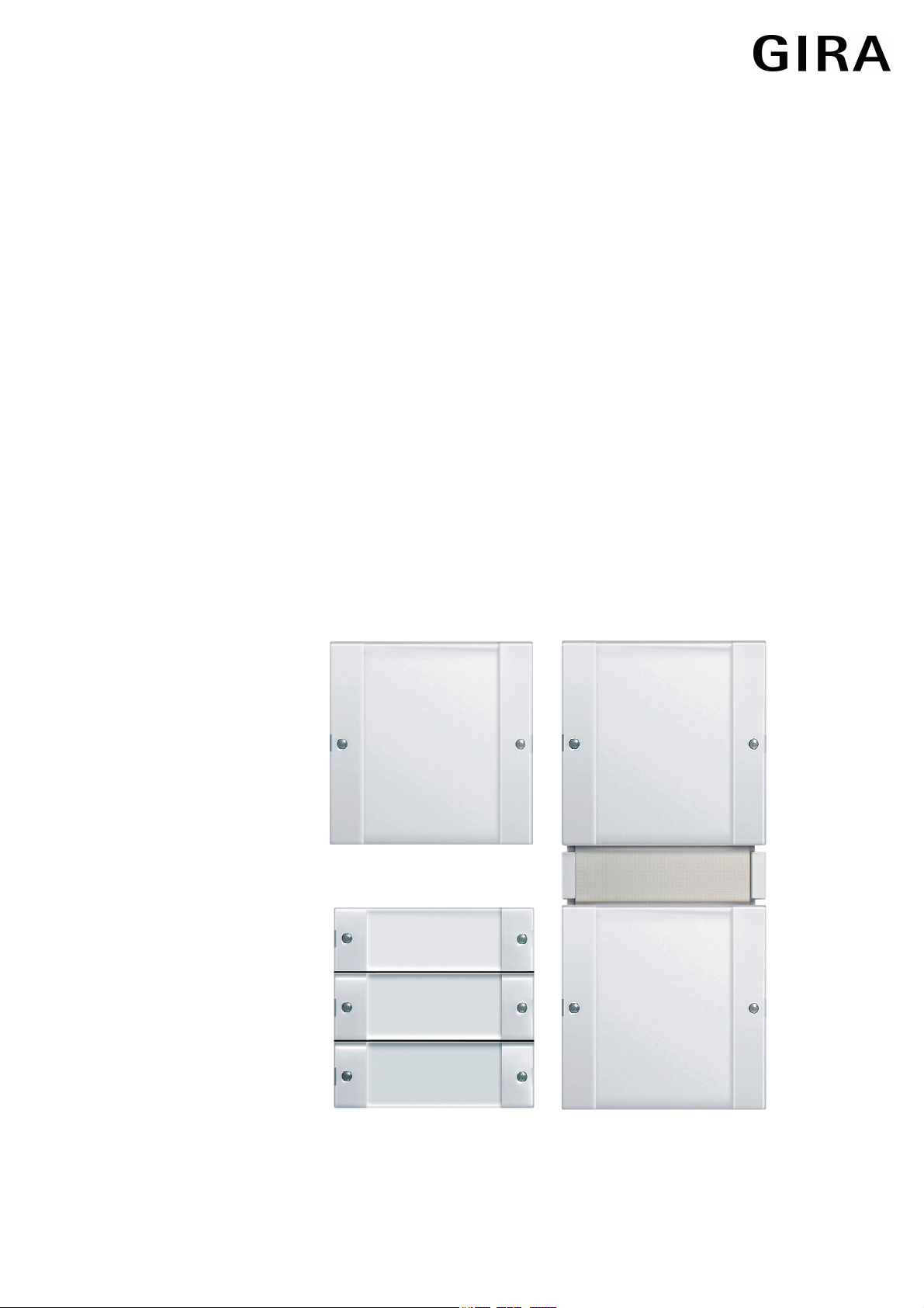
Order No. 5111 00
Order No. 5112 00
Order No. 5113 00
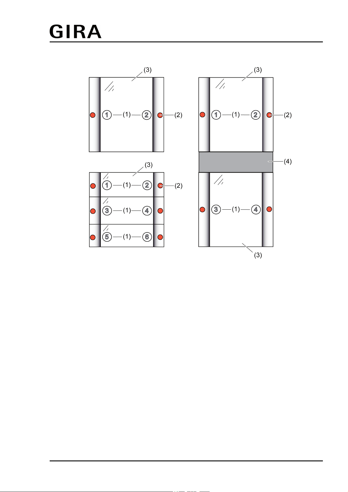
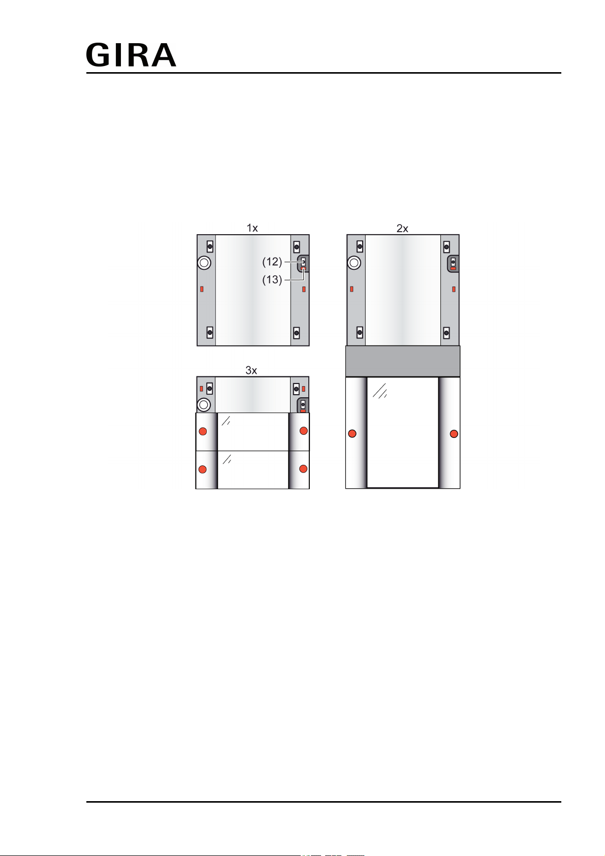
The pushbutton sensor cover must be plugged onto a flush-mounted bus coupling unit 3. Anti-
dismantling protection is provided by screwing to the supporting frame of the bus coupling unit.
In addition, the lower part of the pushbutton sensor cover is screwed to the wall, or in the case
of mounting on 2 appliance boxes, to a second supporting frame. Mounting requires a design
frame 2gang without central web.
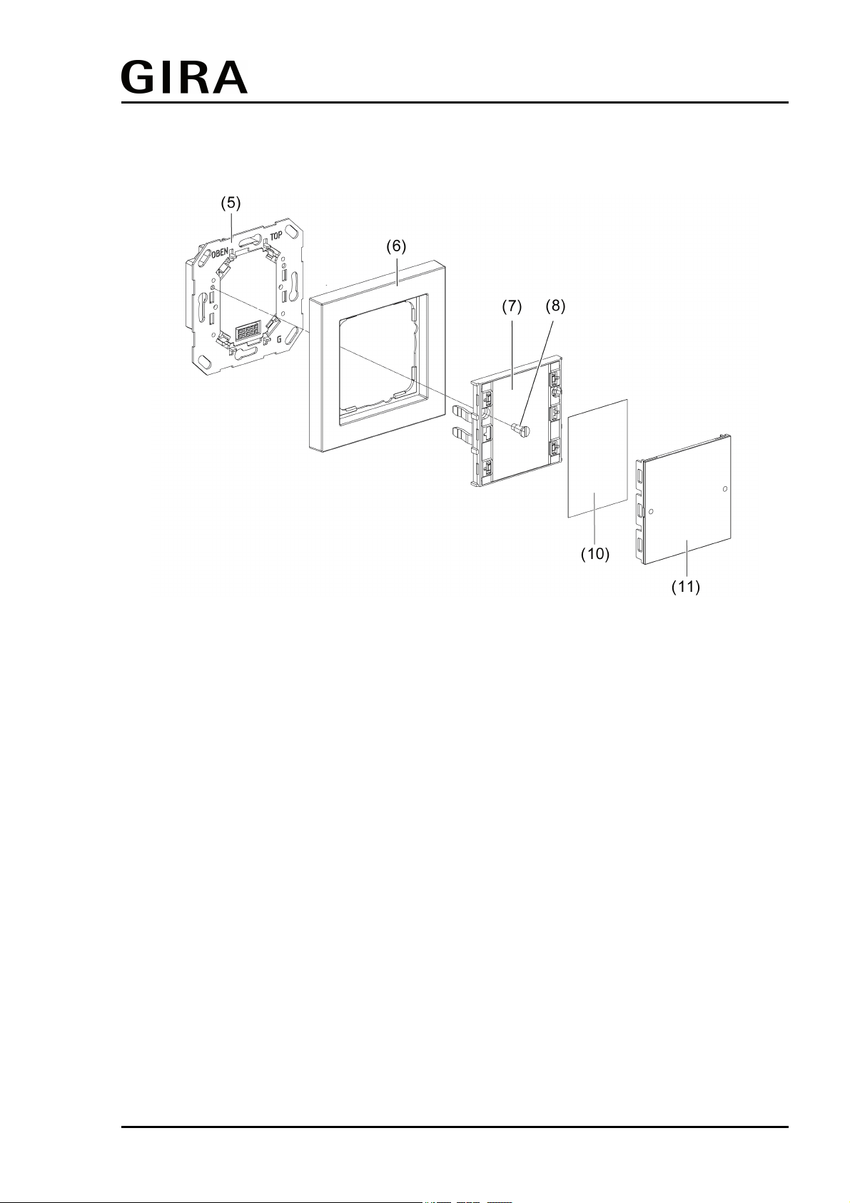
oConnect the bus coupling unit (5) with the KNX/EIB bus cable and fasten in place in an
appliance box.
oRemove the rocker covers (11) and inscription panels (10) from the pushbutton sensor
cover (7).
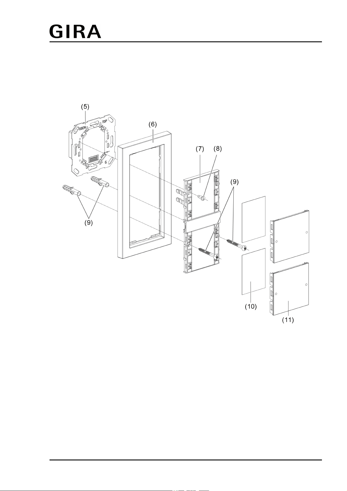
For mounting on only one appliance box, the lower part of the pushbutton sensor cover is
screwed to the wall with the aid of the supplied screw and anchor set (9). To do this, proceed as
follows:
oPosition the design frame 2gang without central web (6) in front of the bus coupling unit
and carefully plug the pushbutton sensor cover into the bus coupling unit.
oMark the drill hole positions on the wall. Do this by using the pushbutton sensor cover as a
template.
oPull the pushbutton sensor off of the flush-mounted bus coupling unit again. Drill holes
(Ø 5mm) and insert the anchors.
iThe use of the anchors depends on the properties of the surface.
oPosition the design frame 2gang without central web in front of the bus coupling unit and
carefully plug the pushbutton sensor cover into the bus coupling unit again.
oScrew the pushbutton sensor cover to the supporting frame of the bus coupling unit. Use
the screw (8) provided.
oIn addition, fasten the lower part of the pushbutton sensor cover in the predrilled holes with
the aid of the wall screws (9).
oIf necessary, label the inscription signs. Optionally the separately available labelling sheets
(see Accessories) can be used.
oFinally, mount the rocker covers together with the labelling panel by snapping them on.
For mounting on two appliance boxes, the lower part of the pushbutton sensor cover is screwed
to a second supporting frame (see Accessories). To do this, proceed as follows:
oMount the second supporting frame on the lower appliance box.
oPosition the design frame 2gang without central web (6) in front of the bus coupling unit
and the second supporting frame and carefully plug the pushbutton sensor cover into the
bus coupling unit.
oScrew the pushbutton sensor cover to the supporting frame of the bus coupling unit. Use
the screw (8) provided.
oScrew the lower part of the pushbutton sensor cover to the second supporting frame. Do
this using the screws included in the scope of supply of the supporting frame.
oIf necessary, label the inscription signs. Optionally the separately available labelling sheets
(see Accessories) can be used.
oFinally, mount the rocker covers together with the labelling panel by snapping them on.
iBefore final fitting of the rocker covers, the physical address has to be loaded into the
device (see page 10).
Page 9 of 23
Installation, electrical connection and operation