Gira CO2-Sensor User manual

KNX
Product documentation
Issue:
24.03.2017
CO2-Sensor with humidity and room temperature
controller
Order No. 2104 ..
21043200

Order No. 2104 ..
Table of Contents
Product definition1 4.................................................................................................................
Product catalogue1.1 4...........................................................................................................
Function1.2 4..........................................................................................................................
Mounting, electrical connection and operation2 6.................................................................
Safety instructions2.1 6...........................................................................................................
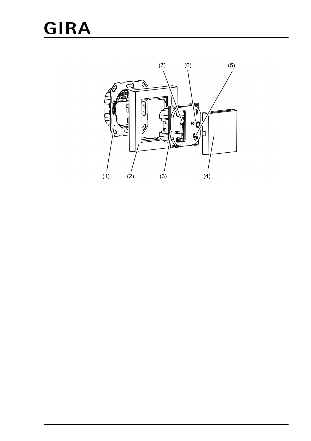
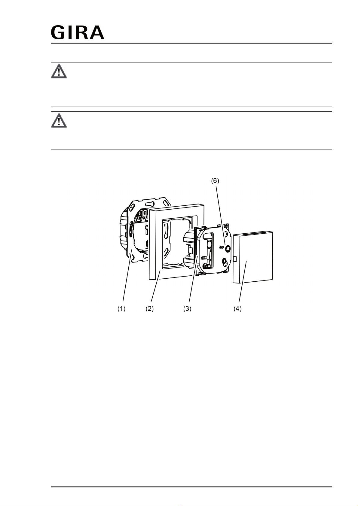
Device components2.2 7........................................................................................................
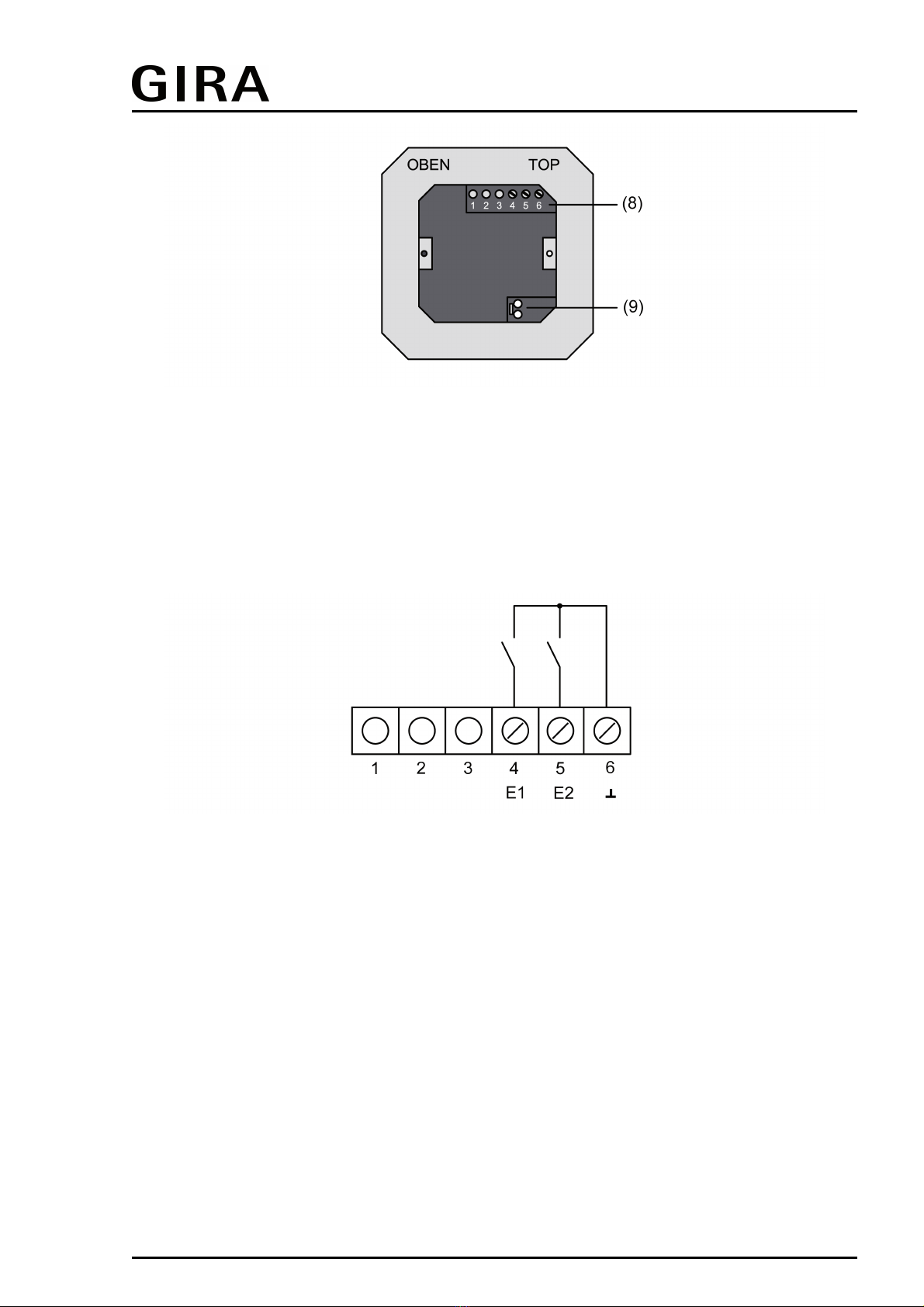
Fitting and electrical connection2.3 8......................................................................................
Commissioning2.4 12.............................................................................................................
Technical data3 13....................................................................................................................
Software description4 14..........................................................................................................
Software specification4.1 14...................................................................................................
Software "KNX CO2 sensor"4.2 15.........................................................................................
Scope of functions4.2.1 15.................................................................................................
Notes on software4.2.2 18..................................................................................................
Object table4.2.3 19...........................................................................................................
Object table push button interface4.2.3.1 19.................................................................
Object table room temperature controller4.2.3.2 22......................................................
Object table sensors4.2.3.3 36......................................................................................
Object table logic gates4.2.3.4 40..................................................................................
Functional description4.2.4 41............................................................................................
Application basics4.2.4.1 41..........................................................................................
Push button interface4.2.4.2 43.....................................................................................
Introduction4.2.4.2.1 43.............................................................................................
Function "no function"4.2.4.2.2 44.............................................................................
"Switching" function4.2.4.2.3 45................................................................................
"Dimming" function4.2.4.2.4 46.................................................................................
"Venetian blind" function4.2.4.2.5 47.........................................................................
Function"Value transmitter 1 byte / 2 byte"4.2.4.2.6 49............................................
Function "Light scene extension with/without memory function"4.2.4.2.7 51............
Response to bus voltage return4.2.4.2.8 52..............................................................
Disabling function of the Inputs4.2.4.2.9 53..............................................................
Sensor function4.2.4.3 54..............................................................................................
Temperature sensor4.2.4.3.1 54...............................................................................
Humidity sensor4.2.4.3.2 55......................................................................................
CO2 sensor4.2.4.3.3 56.............................................................................................
Limiting values4.2.4.3.4 58........................................................................................
Room temperature controller4.2.4.4 64.........................................................................
Operating modes and operating mode change-over4.2.4.4.1 64..............................
Control algorithms and calculation of command values4.2.4.4.2 67.........................
Adapting the control algorithms4.2.4.4.3 75..............................................................
Operating mode switchover4.2.4.4.4 78....................................................................
Temperature setpoints4.2.4.4.5 87............................................................................
Room temperature measurement4.2.4.4.6 99...........................................................
Command value and status output4.2.4.4.7 102.......................................................
Disable functions of the room temperature controller4.2.4.4.8 109...........................
KNX
Product documentation
Page 2 of 171

Order No. 2104 ..
Valve protection4.2.4.4.9 110....................................................................................
Logic gates4.2.4.5 111...................................................................................................
Delivery state4.2.4.6 113...............................................................................................
Parameters4.2.5 114..........................................................................................................
Parameter sensor4.2.5.1 114.........................................................................................
Room temperature controller parameter4.2.5.2 125......................................................
Push button interface parameter4.2.5.3 142..................................................................
Logic gate parameter4.2.5.4 166...................................................................................
Appendix5 170...........................................................................................................................
Index5.1 170...........................................................................................................................
KNX
Product documentation
Page 3 of 171

Order No. 2104 ..
1 Product definition
1.1 Product catalogue
Product name: CO2-Sensor
Use: Sensor
Design: FM (flush-mounted)
Order No. 2104 ..
1.2 Function
The device combines the functions of a KNX bus coupling unit, single-room temperature
controller with setpoint presetting, temperature and humidity sensor and CO2 sensor in one bus
device. The room temperature controller, humidity and CO2-Sensor functions are each
independent function sections of the device with their own parameter blocks in the ETS. The
functions can be configured in the ETS.
In addition, the device has two binary inputs that can be disabled during operation, and by
means of which actuators can be controlled via KNX telegrams, e.g., for controlling fans or
window drives. Through the combination of all functions it is possible to monitor the indoor air
quality and to control measures for preserving the air quality via the bus.
CO2 sensor functionality
The device can be used for determining the CO2 content of the ambient air. Depending on
configured limiting values and current CO2 actual value, telegrams can be transmitted to the
KNX for controlling fans or window drives. Four freely definable limiting values, which can be
used by switching command telegrams for controlling actuators or indications, can be
programmed for this purpose. The CO2 content determined can be transmitted to the bus as a
2-byte measured value via a separate object and be made available to KNX display
components or to supplementary filter units, for example.
Since the measurement of correct values strongly depends on air pressure, a calibration
according to the height of the mounting location above NN (sea level) can be performed with the
aid of the ETS parameters.
Room temperature controller functionality
The device can be used for single-room temperature control. Depending on the operating mode,
the current temperature set value and on the room temperature, a variable for heating or cooling
control can be sent to the KNX. The controller distinguishes between different operating modes
(comfort, standby, night) each with their own temperature setpoints for heating or cooling.
In addition to the heating or cooling basic level, activating an additional heater and/or cooling
unit means that an additional heating or cooling unit can be used. In this connection, you can
set the temperature setpoint difference between the basic and the additional level by a
parameter in the ETS. For major deviations between the temperature setpoint and the actual
temperature, you can activate this additional level to heat up or cool down the room faster.
You can assign different control algorithms to the basic and additional stages. For heating and
cooling functions, you can select continuous or switching PI or switching 2-point feedback
control algorithms.
The room temperature can be recorded either by the internal or by an external temperature
sensor. A KNX communication object is available for the external temperature sensor by means
of which the temperature value received from the external bus, e.g. from a controller extension,
can be integrated into the temperature detection.
Humidity sensor functionality
The device can be used for determining the humidity of the ambient air. Depending on
configured limiting values and the current air humidity, value switching telegrams can be
transmitted to the KNX for controlling fans or window drives. The air humidity determined can be
transmitted to the bus as a 2-byte measured value via a separate object, and in this way, be
Page 4 of 171
Product definition

Order No. 2104 ..
made available to KNX display components.
The value of the air humidity measured by the humidity sensor together with the measured room
temperature is used for calculating the dew point.
Dew point alarm
The dew point of water in the formal sense is the condensation point of pure water and thus a
value pair from air humidity and room temperature. The temperature value of the dew point, i.e.
the dew point temperature, is normally equated with the dew point. This concerns the
temperature of the air with a specific humidity at which the condensation on an object is
currently forming.
The dew point temperature is calculated by the device on the basis of the determined room
temperature and is adjusted by means of the Magnus formula. This is an approximation formula
for calculating the saturated vapour pressure depending on the temperature, which is used in
meteorology and building physics.
The dew point temperature determined can be transmitted to the bus as a 2-byte value via a
separate object and be made available to KNX display components, for example. Once the dew
point temperature has been reached, the device can transmit a dew point alarm to the bus in the
form of switching or value telegrams. This dew point alarm can take place up to a maximum
lead of 5 K in order to realise a pre-warning function.
Functionality of binary inputs
The device has a push-button interface with 2 independent channels and transmits telegrams to
the KNX after activation of a connected switch or push-button contact of a rocker or button
depending on the ETS parameter setting. These can be, for instance, telegrams for switching or
push button control, for dimming or for controlling blinds. It is also possible to program value
transmitter functions such as dimming value transmitters or light scene extensions. These inputs
are lockable during operation. The insert for the presence detector is also possible.
Logic gates
In order to implement logical dependencies from external states as well or to cascade, the
device software has four logic gates. Each gate can have from one to a maximum of four inputs.
The type of logic operation can be set as "AND", "OR", "EXCLUSIVE OR" or as "AND with
feedback" for each logic gate. In addition, each input can be operated normally or inverted.
The communication objects of the outputs can be configured as 1-bit or 1-byte objects. Outputs
that transfer switching commands can also work inverted.
The inputs can either be used separately with their own communication objects or can also, if
necessary, be linked optionally to limiting values of the CO2- and humidity measurement, to the
objects of the dew point alarm or to output objects of other logic functions. The outputs can work
with a time delay if necessary. The transmission criterion for input event, output change and
cyclical transmission can be set. Several logic gates can be combined with each other for
complex logic operation functions.
General
The device is flush mounted in a switchbox and covers the surface of a socket. The device is a
so-called monoblock product. It does not require any separate bus coupling or additional power
supply.
The programming mode of the device is indicated by a separate programming LED. It is located
on the front of the design covers directly next to the programming button and continues flashing
until an application is loaded. In this manner the device can be commissioned easily with the
ETS even in the installed state. Project design and commissioning of the device is performed
using the ETS 3.0d with Patch A or newer versions.
Page 5 of 171
Product definition

Order No. 2104 ..
2 Mounting, electrical connection and operation
2.1 Safety instructions
Electrical equipment may only be installed and fitted by electrically skilled persons.
Failure to observe the instructions may cause damage to the device and result in fire and
other hazards.
Do not use for safety-related gas measurements.
During renovation work, protect the device against soiling through paint, wallpaper
paste, dust, etc. Device can be damaged.
Do not clean or store the device with organic solvents or expose it to their vapours. Do
not stick any adhesive labels. Do not store device in packaging or environments that
contain softening agents, e.g. bubble wrap or polystyrene. Before starting renovation
work, remove the device from the system and store it in a suitable place. The function of
the temperature and humidity sensor may be permanently impaired.
Danger of electric shock on the KNX installation. Do not connect any external voltage to
the inputs. The device might be damaged, and the SELV potential on the KNX bus line
will no longer be available.
Page 6 of 171
Mounting, electrical connection and operation

Order No. 2104 ..
2.2 Device components
Figure 1: Device components CO2 Sensor
(1) Device connection terminal insert
(2) Design frame
(3) Electronics cover
(4) Cover
(5) Programming button and LEDs
(6) Locking screw (plastic)
(7) Sensor window CO2 sensor
Page 7 of 171
Mounting, electrical connection and operation

Order No. 2104 ..
2.3 Fitting and electrical connection
DANGER!
When mounting with 230 V devices under a common cover, e.g. socket outlets,
there is a danger of electrical shocks in the event of a fault!
Electrical shocks can be fatal.
Only use the preassembled plastic screw as locking screw!
CAUTION!
Electrostatic discharges
Device damage.
Only operate the device with cover.
Mounting and connecting the device
Figure 2: Device fitting
(1) Device connection terminal insert
(2) Design frame
(3) Electronics cover
(4) Cover
(6) Locking screw (plastic)
Observe the routing conditions for SELV.
Do not route input cables parallel to mains cables. Otherwise there might be signal interference.
Recommendation: Use a deep appliance box!
The optimum installation height is approx. 1.5 m.
oRemoving the cover (4) (Figure 2).
oIsolate device connection terminal insert (1) from electronic insert (3).
Page 8 of 171
Mounting, electrical connection and operation

Order No. 2104 ..
Figure 3: Device connection terminal insert with connections
(8) Connecting strip binary inputs
(9) KNX connection
oInsert the stripped bus line into the device connection terminal (9) in the device connection
terminal insert (Figure 3)
Figure 4: Connection of binary inputs
1..3 Not assigned
4 Connection binary input E1
5 Connection binary input E2
6 Reference potential E1, E2
oWindow contacts, NO contact or NC contact push-buttons can be connected to device
connection terminal 4, 5 and 6 of the connecting strip binary inputs (8).
oInsert device connection terminal insert (1) in appliance box. Note label OBEN / TOP. The
bus connection must be to the right and below.
oFit the Design frame (2) on device connection terminal insert (1).
oInsert the electronics cover (3) into the device connection terminal insert in the correct
orientation.
oFasten the electronics cover with the locking screw (6).
Page 9 of 171
Mounting, electrical connection and operation

Order No. 2104 ..
oReattach the cover (4).
iDo not use the device in multiple combinations with other FM devices as their heat
generation can influence the temperature and humidity measurement of the controller.
iDo not mount the device near sources of interference such as electric cookers,
refrigerators, draughts or direct sunlight. This also influences the temperature and humidity
reading of the controller.
Dismantling the device
Figure 5: Device dismantling
Design cover and electronics cover should be dismantled during painting and decorating work.
oInsert screwdriver in slot on the bottom of the cover and raise it carefully.
iDo not damage cover and design frame.
oLoosen locking screw in the electronics cover.
oRemove electronics cover from device connection terminal insert.
Page 10 of 171
Mounting, electrical connection and operation

Order No. 2104 ..
iDuring the subsequent fitting, the cover must be mounted again onto the respective insert.
Therefore, please pay attention to the correct labelling of the cover and insert during the
dismantling and label these accordingly.
Page 11 of 171
Mounting, electrical connection and operation

Order No. 2104 ..
2.4 Commissioning
Loading the physical address and application software
The commissioning of the device is basically confined to programming of the physical address
and the application data with the ETS.
Project design and commissioning of the device using the ETS 3.0d with Patch A or newer
versions.
The device is connected and ready for operation.
An appropriate device must be created and configured in the ETS project.
Figure 6: Location of the programming button and LED
The programming button is located behind the blank cover (4) on the electronics cover (3) .The
programming button is located behind the blank cover (4) on the electronics cover (3)
(Figure 6).
oRemove the blank cover (4) if it is already mounted.
oActivating Programming mode: push the programming button (5).
The programming LED (5) lights up red.
oProgram the physical address with the help of the ETS.
The programming LED goes out.
oRecord the physical address on the device connection terminal insert and on the back of
the electronics cover.
iObserve the correct assignment of inserts and covers when assembling after painting or
wallpapering work.
oMount blank cover.
oLoad the application data into the device using the ETS.
iIf the device was programmed with wrong application data, the device is without function
after the commissioning.
Page 12 of 171
Mounting, electrical connection and operation

Order No. 2104 ..
3 Technical data
General
Protection class III
Test mark KNX/EIB
Ambient temperature -5 ... +45°C
Storage/transport temperature +10 ... +50°C
Storage/transport humidity 20 ... 60% rel. humidity
KNX
KNX medium TP
Commissioning mode S-mode
Rated voltage KNX DC 21 ... 32VSELV
Current consumption KNX typ. 12.5mA
Current consumption KNX max. 25mA (4 s/15 s as a cycle)
Connection mode KNX device connection terminal
Binary inputs
Cable length max. 5m
Cable type J-Y(St)Y 2 x 2 x 0.8 mm
CO2 sensor
Measuring range 0 ... 2000ppm
Humidity sensors
Measuring range 10 ... 95% rel. humidity
Temperature sensors
Measuring range -5 ... +45°C
Page 13 of 171
Technical data

Order No. 2104 ..
4 Software description
4.1 Software specification
ETS search paths: - heating, air condition, ventilation / regulator / CO2-Sensor
Configuration: S-mode standard
PEI type: "00"Hex / "0" Dec
PEI connector: none
BAU used: FZE 1066 + µC
Application for CO2 sensor:
No. Short description Name Version from mask
version
1 CO2-/air humidity sensor with room
temperature controller,
2 binary inputs, dew point alarm and
logic gates.
CO2 sensor 706211 1.1
for ETS3.0
Version "d"
Patch "A"
onwards or
ETS4
705
Page 14 of 171
Software specification

Order No. 2104 ..
4.2 Software "KNX CO2 sensor"
4.2.1 Scope of functions
Pushbutton interface funcionality
General
- Free allocation of the functions switching, dimming, Venetian blind and value transmitter to
max. 2 inputs.
- Disable object for disabling individual inputs (polarity of the disable object is adjustable).
- Delay on bus voltage return and debouncing time centrally adjustable.
- The behaviour on bus voltage return can be configured separately for each input.
- Telegram rate limit generally adjustable for all inputs.
Switching function
- Two independent switching objects are available for each input, switching commands can
be configured individually.
- Command can be set independently for rising and falling edge. Executable switching
commands may include "ON", "OFF", "TOGGLE" or "no reaction".
Dimming function
- The choice between single-surface and dual-area operation is possible. Executable
switching commands may include "Brighter (ON)", "darker (OFF)" or "TOGGLE".
- Time between dimming and switching and also the dimming step width is adjustable.
- Cyclical transmission of telegram repetitions as well as transmission of a stop telegram at
the end of a dimming procedure is possible.
"Blind" function
- Command can be set independently for rising edge. Executable switching commands may
include "no function", "UP", "DOWN" or "TOGGLE".
- The operation concept is configurable (short – long – short or long – short).
- In the operation concept Short – Long – Short, the time between short and long-time
operation is adjustable.
- The slat adjusting time is adjustable. This is the time during which a MOVE command can
be terminated by releasing a push-button at the input.
Function value transmitter (dimming, temperature, brightness)
- The edge (push-button as NO contact, push-button as NC contact, switch) and the value to
be transmitted are configurable on edge.
- When programming as a push-button, the value for the value transmitter can be adjusted
by a long button-press.
Function light scene extension
- Configuration as light scene extension with or without memory function. In the light scene
extension with memory function, a light scene can be stored by a long press of the
connected push-button.
- The edge (push-button as NO contact, push-button as NC contact, switch) and the value to
be transmitted are configurable on edge.
Room temperature controller functionality
General
- 4 various operating modes can be activated: Comfort, Standby, Night and Frost/heat
protection
- The operating mode switchover is performed via 1-byte object according to the KNX
specification or using up to four individual 1-bit objects.
Heating / cooling
- The operating modes "Heating", "Cooling" or "Heating and Cooling" are available with or
without additional level.
Page 15 of 171
Software "KNX CO2 sensor"
Scope of functions

Order No. 2104 ..
- The control algorithms of the temperature control are configurable, either the switching
2-point feedback control, the switching PI control (PWM) or the continuous PI control.
- The command value output 1-bit (switching) or 1-byte (continuous).
- The adjustable control parameters for the PI control are "Proportional range" and "Reset
time", for the 2-point feedback control "Hysteresis".
Setpoint values
- Each operating mode can be assigned its own temperature-setpoints (for heating and/or
cooling).
- The setpoints for the additional level are derived by a configurable level offset from the
values of the basic setpoint.
- The basic setpoint shift is possible by means of communication objects.
Functions
- Switching between "Heating" and "Cooling" can be automatic or object-oriented.
- Deactivating the feedback control possible using separate 1-bit objects.
- The comfort extension is possible by pressing a configurable presence button or presence
detector in the night or frost/heat protection mode.
- The length of the comfort extension can be parameterized.
- The status information is configurable and can be transmitted to the bus via an object
(1-byte / 1-bit).
- Deactivating the feedback control or the additional level is possible using separate 1-bit
objects.
Room temperature measurement
- The room temperature can be measured by means of an internal or external room
temperature sensor. The external temperature sensor must be a KNX temperature sensor
coupled via the bus. Alternatively, both temperature sensors can be combined together.
The determination of the measured value from the internal to external sensor is
configurable.
- The polling time of the external temperature sensor is settable.
- The change interval for the automatic transmission of the actual temperature can be
defined in the ETS. Cyclical transmission of the room temperature is possible, too.
- The room temperature measurement (actual value) can be adjusted separately for the
internal and external sensor using parameters.
- The frost protection mode switch-over is possible by the window status or by the automatic
frost protection.
Actuating variable output
- The separate or shared command value output in heating and cooling mode is possible.
This produces one or two command value objects for each level.
- Normal or inverted command value output is configurable
- Automatic transmission and cycle time for command value output are configurable.
Humidity sensor functionality
Humidity measurement
- The humidity is measured by the integrated measuring element.
- Two limiting values can be assigned to the humidity measured value, and if exceeded or
fallen short of, ventilation controllers can be activated, for example.
Dew point determination
- The dew point temperature is calculated by the device on the basis of the determined room
temperature.
- The determined humidity value of the sensor is adjusted by means of the Magnus formula
which is an approximation formula for calculating the saturated vapour pressure depending
on the temperature. It is very accurate (< 0.22 %) in the range between 0°C and 100°C and
is primarily used in meteorology and building physics for determining the dew point.
Page 16 of 171
Software "KNX CO2 sensor"
Scope of functions

Order No. 2104 ..
CO2 controller functionality
iAfter switch-on, the CO2 sensor requires a warm-up period of up to 5 minutes, until normal
operation is reached.
The automatic calibration method is only available in the case of permanent power supply
and after 24 hours for the first time.
CO2 measurement
- The CO2 is measured by means of the integrated sensor module.
- The "height of the location above sea level" is configurable because the exact measured
value of the CO2 sensor is air pressure dependent.
Limiting values
- Four limiting values can be assigned to the CO2 measured value, and if exceeded or fallen
short of, ventilation controllers can be activated, for example.
- The hysteresis and behaviour can be specified for all limiting values should the limiting
value be exceeded or undershot.
- A switch-on and switch-off delay can be configured for all limiting values (also applies to
cyclical transmission).
- The transmission criterion cyclical transmission is configurable for all limiting values.
Logic gates functionality
- Up to four logic gates with one up to a maximum of four inputs can be configured. Each of
the inputs can be operated normal or inverted.
- Possible logic operations are "AND", "OR", "Exclusive OR" or "AND with return".
- The communication objects of the outputs can be configured as 1-bit or 1-byte objects.
- The transmission criterion for input event, output change and cyclical transmission can be
set.
- The transmission delay can be configured individually for all logic gates.
Page 17 of 171
Software "KNX CO2 sensor"
Scope of functions

Order No. 2104 ..
4.2.2 Notes on software
ETS project design and commissioning
For project design and commissioning of the device, ETS3.0 from Version "d" Patch "A"
onwards or ETS4 is required. Through use of these ETS version, advantages are gained with
regard to the programming process (differential download).
The necessary product database is offered in the *.VD4 format.
A plug-in integrated in the ETS product database permits the configuration.
Page 18 of 171
Software "KNX CO2 sensor"
Notes on software

Order No. 2104 ..
4.2.3 Object table
Number of communication objects: 139
(max. object number 138 - gaps in between)
Number of addresses (max): 254
Number of assignments (max): 255
Dynamic table management no
4.2.3.1 Object table push button interface
Objects of the push button interface
Function: Switching
Object
h0, 1
Function
Switching object 1.1
Name
B.Channel 1 / 2
Type
1-bit
DPT
1,001
Flag
C, W, T,
(R)1
Description 1-bit object for transmission of switching telegrams (ON, OFF, TOGGLE).
Function: Switching
Object
h2, 3
Function
Switching object 1.2
Name
B.Channel 1 / 2
Type
1-bit
DPT
1,001
Flag
C, W, T,
(R) 1
Description 1-bit object for transmission of switching telegrams (ON, OFF, TOGGLE).
Function: Dimming
Object
h0, 1
Function
Switching
Name
B.Channel 1 / 2
Type
1-bit
DPT
1,001
Flag
C, W, T,
(R)1
Description 1-bit object for transmission of switching telegrams (ON, OFF, TOGGLE).
Function: Dimming
Object
h2, 3
Function
Dimming
Name
B.Channel 1 / 2
Type
4-bit
DPT
3,007
Flag
C, W, T,
(R)1
Description 4-bit object for the transmission of relative dimming telegrams.
Function: Venetian blind
Object
h0, 1
Function
Short time operation
Name
B.Channel 1 / 2
Type
1-bit
DPT
1,007
Flag
C, T (R)1
Description 1-bit object for the transmission of telegrams with which a Venetian blind or
shutter drive motor can be stopped or with which the blind slats can be
adjusted by short time operation.
1: Each communication object can be read out. For reading, the R-flag must be set.
Page 19 of 171
Software "KNX CO2 sensor"
Object table

Order No. 2104 ..
Function: Venetian blind
Object
h2, 3
Function
Long-time operation
Name
B.Channel 1 / 2
Type
1-bit
DPT
1,008
Flag
C, W, T,
(R)1
Description 1-bit object for the transmission of telegrams with which a Venetian blind or
shutter drive motor can be can be moved upwards or downwards.
Function: Value transmitter
Object
h0, 1
Function
Dimming value
Name
B.Channel 1 / 2
Type
1
bytes
DPT
5,001
Flag
C, T (R)1
Description 1-byte object for the transmission of values from 0 to 255 (corresponding to
values from 0 % to 100 %). If the adjustment of the value is enabled, the
object can transmit telegrams cyclically after long actuation with which the
value can be reduced or increased by a presettable amount.
Function: Value transmitter
Object
h0, 1
Function
Scene extension
Name
B.Channel 1 / 2
Type
1
bytes
DPT
18,001
Flag
C, T (R)1
Description 1-byte object for recalling or storing one of a maximum of 64 scenes of a
scene push-button or actuator with scene function.
Function: Value transmitter
Object
h0, 1
Function
Temperature value
Name
B.Channel 1 / 2
Type
2
bytes
DPT
9,001
Flag
C, T (R)1
Description 2 -byte object for the transmission of a temperature value from 0 °C to 40 °C.
If the adjustment of the value is enabled, the object can transmit telegrams
cyclically after a long press with which the value can be reduced or increased
by 1 K.
Function: Value transmitter
Object
h0, 1
Function
Brightness value
Name
B.Channel 1 / 2
Type
2
bytes
DPT
9,004
Flag
C, T (R)1
Description 2-byte object for the transmission of a brightness level value from 0 to 1500
lux. If the adjustment of the value is enabled, the object can transmit cyclical
telegrams after a long press with which the value can be reduced or increased
by 50 lux.
1: Each communication object can be read out. For reading, the R-flag must be set.
Page 20 of 171
Software "KNX CO2 sensor"
Object table
Table of contents
Other Gira Accessories manuals

Gira
Gira 5068 00 User manual

Gira
Gira 1170 Series User manual

Gira
Gira 5112 00 Operator's manual

Gira
Gira 5471 00 User manual

Gira
Gira 5069 00 User manual

Gira
Gira 1025 00 User manual

Gira
Gira System 55 Pushbutton sensor 4 Standard User manual

Gira
Gira 0384 00 User manual

Gira
Gira Observer 110 User manual

Gira
Gira 0551 4 Series User manual
Popular Accessories manuals by other brands

Johnson Controls
Johnson Controls WRZ-TTB0000-5 installation guide

aci
aci VOC-ROOM Installation and operation instruction

Xantech
Xantech SMAUD01 installation instructions

Lea
Lea NETFILTER NANO Quick installation guide

Omron
Omron E3X-DAC-S Series manual

Cornelius
Cornelius Post-Mix Valves UFB-1 Training manual