manuals.online logo
Brands
  1. Home
  2. •
  3. Brands
  4. •
  5. Gira
  6. •
  7. Accessories
  8. •
  9. Gira Touch sensor 2 User manual

Gira Touch sensor 2 User manual

GIRA
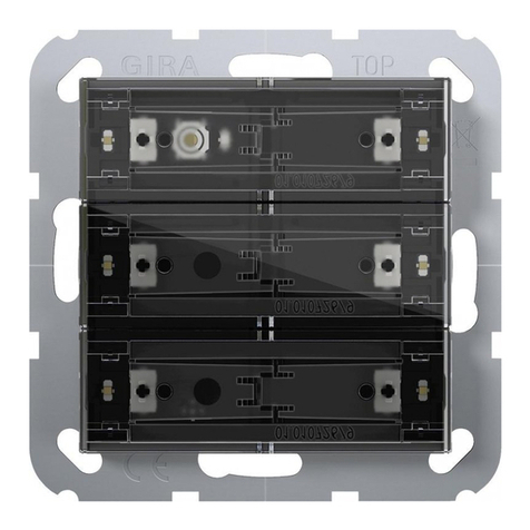
Info Touch sensor 2, 24 V potential-free
Installation Instructions
Touch sensor 2, 24 V potential-free 3/12 Page 1 of 3
Function
• touch sensors for connection to 24 V control
systems
• two red status indication LEDs for each rocker
• backlighting
• connection with terminal block at the rear
Connection
Button outputs and LED inputs (FIG. B)
Touch sensor 2, 24 V potential-free
single
triple Order no.: 2001 ..
Order no.: 2003 ..
Sensor terminal
(upper row) assigned
rocker: LED terminal
(lower row)
triple single
1 1 left 1 left 1
2 1 right 1 right 2
3 2 left ---- 3
42right---- 4
5 3 left ---- 5
63right---- 6
---- ---- 7
lighting 8
GIRA
Info Touch sensor 2, 24 V potential-free
Installation Instructions
Touch sensor 2, 24 V potential-free 3/12 Page 2 of 3
Fitting (FIG. C)
1. Remove rockers (5) carefully from touch sensor.
2. Install housing base (1) in the wall.
3. Place design frame (2) over the base and connect
touch sensor (3) to the control system.
4. Plug touch sensor (3) into the base (1).
5. Fasten touch sensor to the base using only the
screws supplied (4)..
6. Slide inscription foil (6) into the touch sensor be-
tween the lateral guides.
Important: If necessary, label foil (6) before fitting.
7. Snap rockers (5) onto the touch sensor.
Removal (FIG. D)
1. Use your thumb and index finger to hold the rocker
on the right and left side.
2. Slide the rocker to the right (1) (or to the left) and
then pull forwards (2) on the right or left side.
3. Loosen the retaining screws
4. If other devices are installed under the same frame
(e.g. socket outlets), they must be detached from
the base as well.
5. Withdraw the touch sensor from the base.
i
Important: Without the retaining
screws the device will not function
properly.
Safety warnings
Attention:Electricalequipmentmustbe installed
and fitted by qualified electricians only.
Failure to observe any of the installation instruc-
tions may cause damage to the device and result
in fire and other hazards.
This device is a safety class III device. Never con-
nect to voltages other than 24 V SELV circuits
(no mains potential !!).
GIRA
Info Touch sensor 2, 24 V potential-free
Installation Instructions
Touch sensor 2, 24 V potential-free 3/12 Page 3 of 3
Technical data
Touch sensor rated
voltage: AC/DC 24 V SELV
LED rated voltage: DC 24 V SELV
Contact current: max. 20 mA per contact
LED current: approx. 1 mA per LED
Connection: 2 x terminal block 9-pole
0.4...0.8 mm single-wire
Power consumption: max. 0.2 W (all LEDs on)
Type of protection: IP 20
Safety class: III
Ambient temperature: -5 °C ... +45 °C
Storage / transport
temperature: -25 °C ... +70 °C
Warranty
The warranty is provided in accordance with statutory requirements via the specialist trade.
Please submit or send faulty devices postage paid together with an error description to your responsible sales-
person (specialist trade/installation company/electrical specialist trade).
They will forward the devices to the Gira Service Center.
Giersiepen GmbH & Co. KG
Electrical Installation
Systems
P.O. Box 12 20
42461 Radevormwald
Germany
Phone +49 (0) 21 95 / 602 - 0
Fax +49 (0) 21 95 / 602 - 191
www.gira.com
[email protected]

Other Gira Accessories manuals

Gira CO2-Sensor User manual

Gira

Gira CO2-Sensor User manual

Gira 5466 02 User manual

Gira

Gira 5466 02 User manual

Gira Observer 110 User manual

Gira

Gira Observer 110 User manual

Gira Observer 70 User manual

Gira

Gira Observer 70 User manual

Gira 5069 00 User manual

Gira

Gira 5069 00 User manual

Gira 5471 00 User manual

Gira

Gira 5471 00 User manual

Gira 5112 00 Operator's manual

Gira

Gira 5112 00 Operator's manual

Gira EDA 3902 F User manual

Gira

Gira EDA 3902 F User manual

Gira 5111 00 User manual

Gira

Gira 5111 00 User manual

Gira 1117 00 User manual

Gira

Gira 1117 00 User manual

Gira 5472 02 User manual

Gira

Gira 5472 02 User manual

Gira KNX 5011 00 User manual

Gira

Gira KNX 5011 00 User manual

Gira System 106 User manual

Gira

Gira System 106 User manual

Gira 5472 02 User manual

Gira

Gira 5472 02 User manual

Gira GEDU 10 Guide

Gira

Gira GEDU 10 Guide

Gira 1493 00 User manual

Gira

Gira 1493 00 User manual

Gira 0384 00 User manual

Gira

Gira 0384 00 User manual

Gira 5142 00 Operator's manual

Gira

Gira 5142 00 Operator's manual

Gira 1170 Series User manual

Gira

Gira 1170 Series User manual

Gira 1025 00 User manual

Gira

Gira 1025 00 User manual

Gira KNX/EIB User manual

Gira

Gira KNX/EIB User manual

Gira 5461 02 User manual

Gira

Gira 5461 02 User manual

Gira 0873 00 User manual

Gira

Gira 0873 00 User manual

Gira 5466 02 User manual

Gira

Gira 5466 02 User manual

Popular Accessories manuals by other brands

Qimarox PRORUNNER Mk5 user manual

Qimarox

Qimarox PRORUNNER Mk5 user manual

Dicota BluePoint user guide

Dicota

Dicota BluePoint user guide

Champion EASYBIRD AUTO-FEED 6 - PACKER instruction manual

Champion

Champion EASYBIRD AUTO-FEED 6 - PACKER instruction manual

Avidsen Bamboo manual

Avidsen

Avidsen Bamboo manual

Detech GATE WL manual

Detech

Detech GATE WL manual

Sunshower PURE WHITE installation guide

Sunshower

Sunshower PURE WHITE installation guide

New Life Radiology MQI006-0 Use and maintenance manual

New Life Radiology

New Life Radiology MQI006-0 Use and maintenance manual

Hatching Time CIMUKA HB Series user manual

Hatching Time

Hatching Time CIMUKA HB Series user manual

RADWAG PUE 7.1 user manual

RADWAG

RADWAG PUE 7.1 user manual

DIAL PEC-A-7500-1M user manual

DIAL

DIAL PEC-A-7500-1M user manual

Crivit 329794 1907 Assembly instructions

Crivit

Crivit 329794 1907 Assembly instructions

Caravan M-Series 2 Pro Reference manual

Caravan

Caravan M-Series 2 Pro Reference manual

Lenovo PA10400 quick start guide

Lenovo

Lenovo PA10400 quick start guide

Thermo Scientific 310 Series user manual

Thermo Scientific

Thermo Scientific 310 Series user manual

Lightolier 1004F26ESR specification

Lightolier

Lightolier 1004F26ESR specification

woundwo TRENDLINE SMARTBOX Mounting instructions

woundwo

woundwo TRENDLINE SMARTBOX Mounting instructions

Panasonic Light Emitting Diodes LN360GPX Specifications

Panasonic

Panasonic Light Emitting Diodes LN360GPX Specifications

Vega VEGAFLEX 81 operating instructions

Vega

Vega VEGAFLEX 81 operating instructions

manuals.online logo
manuals.online logoBrands
  • About & Mission
  • Contact us
  • Privacy Policy
  • Terms and Conditions

Copyright 2025 Manuals.Online. All Rights Reserved.