Gira System 55 Pushbutton sensor 4 Standard User manual

Pushbutton sensor 4 Standard / Komfort System 55
Pushbutton sensor 4 Standard, 1-gang System 55
Order no.: 5011 00
Pushbutton sensor 4 Standard, 2-gang System 55
Order no.: 5012 00
Pushbutton sensor 4 Standard, 3-gang System 55
Order no.: 5013 00
Pushbutton sensor 4 Komfort, 1-gang System 55
Order no.: 5041 00
Pushbutton sensor 4 Komfort, 2-gang System 55
Order no.: 5042 00
Pushbutton sensor 4 Komfort, 3-gang System 55
Order no.: 5043 00
Operating instructions
1 Safety instructions
Electrical devices may only be mounted and connected by electrically skilled persons.
Serious injuries, fire or property damage possible. Please read and follow manual fully.
Danger of electric shock. During installation and cable routing, comply with the regulations and
standards which apply for SELV circuits.
This manual is an integral part of the product, and must remain with the end customer.
1 / 16
32406202 10868646 29.06.2022

Pushbutton sensor 4 Standard / Komfort System 55
2 Device components
Front view
Figure1: Device components 3-gang ("standard installation location", horizontal rockers)
Figure2: Device components 3-gang (installation location "turned by -90°", vertical rockers)
(a) Operating rockers (accessory)
(b) Status LED
1...6 Push-buttons assignment and status LED
2 / 16
32406202 10868646 29.06.2022

Pushbutton sensor 4 Standard / Komfort System 55
Rear view
Figure3: Device components - rear side
(c) Device connection terminal for remote sensor (only for "comfort" device variant)
(d) Device connection terminal KNX
(e) Retaining clips for device fixation at the supporting frame
(f) Supporting frame
3 / 16
32406202 10868646 29.06.2022

Pushbutton sensor 4 Standard / Komfort System 55
3 System information
This device is a product of the KNX system and complies with the KNX directives. Detailed tech-
nical knowledge obtained in KNX training courses is a prerequisite to proper understanding.
The function of this device depends upon the software. Detailed information on loadable soft-
ware and attainable functionality as well as the software itself can be obtained from the manu-
facturer´s product database.
The device can be updated. Firmware can be easily updated with the Gira ETS Service App
(additional software).
The device is KNX Data Secure capable. KNX Data Secure offers protection against manipula-
tion in building automation and can be configured in the ETS project. Detailed specialist know-
ledge is required. A device certificate, which is attached to the device, is required for safe com-
missioning. During mounting, the device certificate must be removed from the device and stored
securely.
Planning, installation and commissioning of the device are carried out with the aid of the ETS,
version 5.7.5 and above.
4 Intended use
– Operation of loads, e.g. light on/off, dimming and colour temperature control, colour con-
trol and brightness, Venetian blinds up/down, 1 byte values, 2 byte values, 3 byte values
and 6 byte values, brightness values, temperatures, colour temperature values, calling up
and saving light scenes as scene extension
– Calling up and saving device-internal light scenes (only for "comfort" device variant)
– Measurement of the room temperature
– Measurement of the room temperature (only for "comfort" device variant)
– Indication of an alarm (only for "comfort" device variant)
– For use as orientation lighting
– Installation in appliance box according to DIN 49073
– Horizontal installation location in the "standard installation location" or vertical installation
location in the "turned by -90°" installation location
4 / 16
32406202 10868646 29.06.2022

Pushbutton sensor 4 Standard / Komfort System 55
5 Product characteristics
Product characteristic per product variant Comfort Standard
Push-button sensor functions switching, dimming and
colour temperature control, colour control and bright-
ness, Venetian blind, value transmitter, scene exten-
sion, 2-channel operation and controller extension ad-
justable
> >
Controller extension with operating mode selection,
forced operating mode switch over, presence function
and setpoint shift
> >
Status LED – optionally red, green, blue - adjustable per
button > >
Status LED - optionally red, green, blue, yellow, cyan,
orange, violet, white - adjustable per button >-
LED functions orientation lighting and night reduction
can be set separately > >
LED functions orientation lighting, alarm signalling and
night reduction can be set separately >-
Brightness of LED adjustable and switchable while in
operation > >
Disable or function switch-over of all or of individual but-
ton functions possible with disabling function > >
Scene control up to 8 scenes with 8 scene outputs each >-
Temperature measurements optionally with device in-
ternal sensor and external sensor connected via com-
munication object
> >
Temperature measurements optionally with device in-
ternal sensor, wired sensor to the device connection ter-
minal and external sensor connected via communication
object
>-
Room humidity measurement with internal device hu-
midity sensor >-
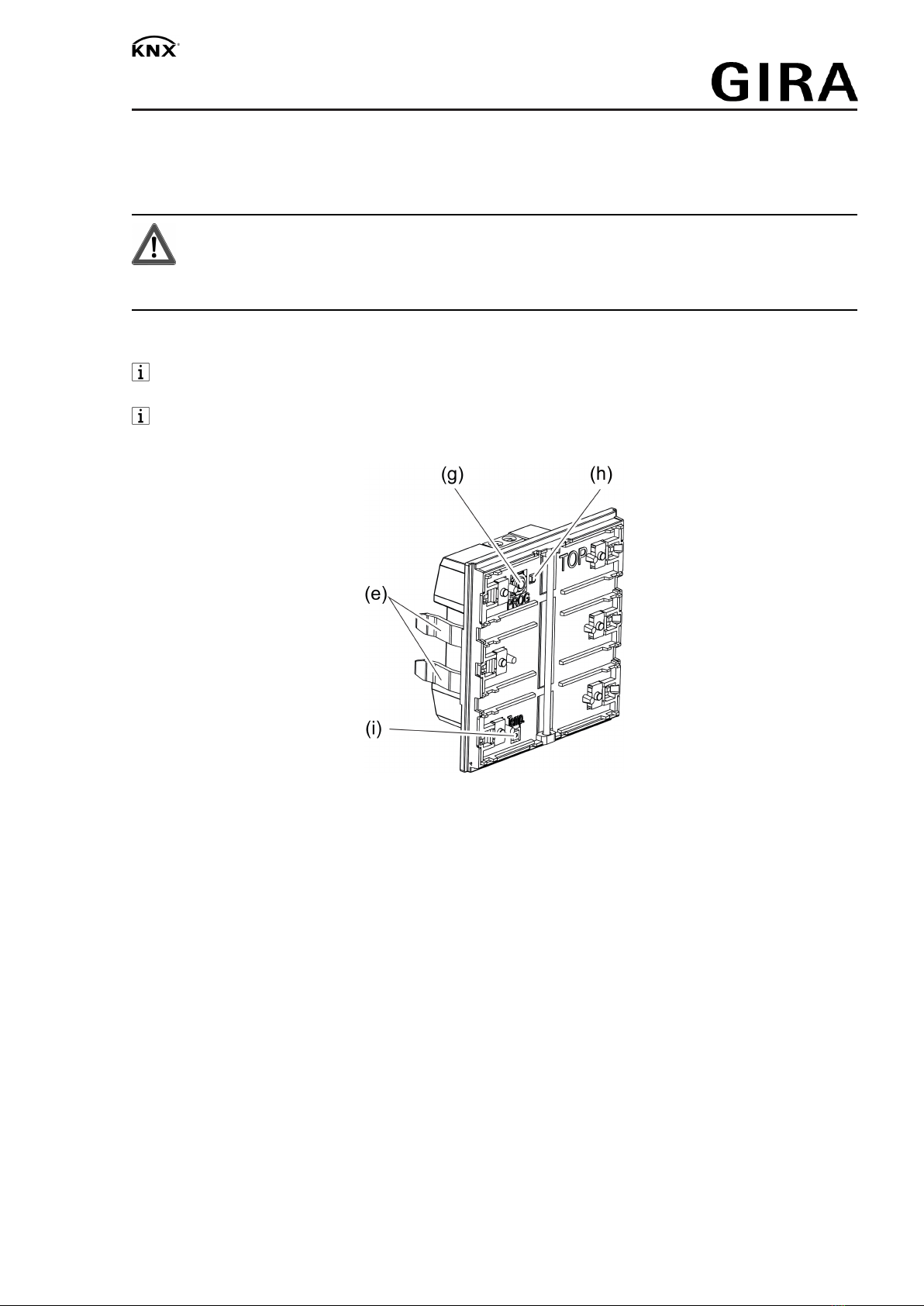
Integrated bus coupling unit > >
5 / 16
32406202 10868646 29.06.2022

Pushbutton sensor 4 Standard / Komfort System 55
6 Operation
Depending on the programming, a rocker can have up to two functions assigned to it. Operation
is carried out by short or long pressing the buttons and depends on the specific function.
6.1 Examples for operating various standard applications
■ Switch: Short press on button.
■ Dim: Long press on the button. The dimming process ends when the button is released.
■ Move Venetian blind: Long press on button.
■ Stop or adjust Venetian blind: Short press on button.
■ Set value, e.g. brightness or temperature setpoint: Short press on button.
■ Open scene: Short press on button.
■ Save scene: Long press on button.
■ Execute channel 1: Short press on button.
■ Execute channel 2: Long press on button.
■ Operate controller extension: Short press on button.
6 / 16
32406202 10868646 29.06.2022

Pushbutton sensor 4 Standard / Komfort System 55
7 Information for electrically skilled persons
7.1 Mounting and electrical connection
DANGER!
Mortal danger of electric shock.
Cover up live parts in the installation environment.
The push-button sensor (Figure 4) can be installed horizontally ("standard installation location")
or vertically ("turned by -90°" installation location).
For horizontal installation ("standard installation location") the top of the push-button
sensor is labelled with TOP.
For vertical installation ("turned by -90°" installation location) the left side of the push-but-
ton sensor is labelled with TOP.
Figure4: Push-button sensor
(e) Retaining clips for device fixation at the supporting frame
(g) Programming button
(h) Programming LED
(i) Temperature sensor
7 / 16
32406202 10868646 29.06.2022

Pushbutton sensor 4 Standard / Komfort System 55
Mounting and connecting the device
Figure5: Mounting the device
(a) Operating rockers (accessory)
(e) Retaining clips for device fixation at the supporting frame
(f) Supporting frame
(k) Cover frame (accessory)
(l) Push-button sensor
(m) Box screws
The device should be used in an air-tight appliance box. Otherwise temperature and hu-
midity reading can be negatively influenced by draughts.
In secure operation (preconditions):
– Secure commissioning is activated in the ETS.
– Device certificate entered/scanned or added to the ETS project. A high resolution camera
should be used to scan the QR code.
– Document all passwords and keep them safe.
Precondition: The installation location of the push-button sensor is defined.
■ Mount supporting frame in the right orientation, "standard installation location" or "turned
by -90°", on an appliance box.
Note the TOP marking.
Use the supplied box screws.
■ Pull off start-up rockers from push-button sensor.
The push-button sensor is delivered with start-up rockers. The operating rockers suitable
for the push-button sensor must be ordered separately (see accessories).
■ Connect push-button sensor to the KNX using KNX connecting terminal (red = +,
black = -).
■ In secure operation: The device certificate must be removed from the device and stored
securely.
■ Optional (only for "comfort" device variant): Connect remote sensor (see accessories) to
device connection terminal.
■ Fit the cover frame flushly. The cover frame is fixed via the push-button sensor.
■ Attach the push-button sensor with cover frame onto the supporting frame.
Push-button sensor can be put into operation.
Make sure the that the retaining clips properly fit in the supporting frame.
8 / 16
32406202 10868646 29.06.2022

Pushbutton sensor 4 Standard / Komfort System 55
7.2 Commissioning
Programming the physical address and application program
Project design and commissioning with ETS from version 5.7.5 and above.
The programming button is located under the first rocker.
Precondition: The device is connected and ready for operation.
The first rocker is dismantled.
■ Activating Programming mode: push the programming button.
The programming LED lights up red. Programming mode is activated.
■ Programming the physical address.
The programming LED goes out. Physical address is programmed.
■ Programming the application program.
The device is for use.
All status LEDs are switched off while the application program is programmed. As soon as
the programming is successfully completed, the status LEDs carry out their parameterised
function.
Only for "comfort" device variant: When the application program is discharged and the
bus voltage is connected, all status LEDs initially light up white. Whenever a button is ac-
tuated, the respective illuminated status LED changes colour in (white → red → green →
blue → yellow → cyan → orange → violet → white → ...).
Only for "standard" device variant: When the application program is discharged and the
bus voltage is connected, all status LEDs initially light up green. Whenever a button is ac-
tuated, the respective illuminated status LED changes colour (green → red → blue → green
→ ...).
10 / 16
32406202 10868646 29.06.2022

Pushbutton sensor 4 Standard / Komfort System 55
7.2.1 Safe-state mode
The safe-state mode stops the execution of the loaded application program.
If the device does not work properly - for instance as a result of errors in the project design or
during commissioning - the execution of the loaded application program can be halted by activ-
ating the safe-state mode. The device remains passive in safe-state mode, since the application
program is not being executed (state of execution: terminated).
Only the system software of the device is still functional. ETS diagnosis functions and pro-
gramming of the device are possible.
Activating safe-state mode
■ Switch off the voltage.
■ Press and hold down the programming button.
■ Switch on voltage.
The safe-state mode is activated. The programming LED flashes slowly (approx. 1 Hz).
Release the programming button only after the programming LED starts flashing.
Deactivating safe-state mode
■ Switch off the voltage or carry out ETS programming.
7.2.2 Master reset
The master reset restores the basic device settings (physical address 15.15.255, firmware re-
mains in place). The device must then be recommissioned with the ETS.
In secure operation: A master reset deactivates device security. The device can then be
recommissioned with the device certificate.
Devices can be reset to factory settings with the ETS Service App. This function uses the
firmware contained in the device that was active at the time of delivery (as-delivered
state). Restoring the factory settings causes the devices to lose their physical address
and configuration.
If the device - for instance as a result of errors in the project design or during commissioning -
does not work properly, the loaded application program can be deleted from the device by per-
forming a master reset. The master reset resets the device to delivery state. Afterwards, the
device can be put into operation again by programming the physical address and application
program.
Performing a master reset
Precondition: The safe-state mode is activated.
■ Press and hold down the programming button for > 5 seconds until the programming LED
starts flashing quickly.
■ Release the programming button.
The device performs a master reset. The programming LED is switched on.
The device restarts and is in delivery state.
11 / 16
32406202 10868646 29.06.2022

Pushbutton sensor 4 Standard / Komfort System 55
7.3 Mounting the rockers
■ Slide the side of the rocker into place (Figure 6).
Figure6: Slide one side of the rocker into place
■ Press in the middle of the rocker (Figure 7).
Figure7: Press lightly in the middle of the rocker
The rocker snaps into place.
Device is ready for operation.
In order to optimise the gap dimensions between the rockers and the cover frame, the
rockers can be moved slightly after snapping into place.
12 / 16
32406202 10868646 29.06.2022

Pushbutton sensor 4 Standard / Komfort System 55
7.4 Dismantling
■ Carefully pull the push-button sensor forward together with the cover frame.
■ Pull the rockers on one side to loosen them from the push-button sensor.
Figure8: Dismantle the push-button sensor
13 / 16
32406202 10868646 29.06.2022

Pushbutton sensor 4 Standard / Komfort System 55
7.5 Exchanging labelling field
The rocker has a labelling field
■ Search for a notch in the cover of the labelling field by feeling with a finger (Figure 9).
■ Pull on one side at the notch in the cover of the labelling field to separate from the rocker
(Figure 10).
The labelling field is uncovered.
Figure9: Feel for a notch in the labelling field cover
Figure10: Remove the labelling field cover
■ Exchange the labelling field.
■ Press the cover of the labelling field onto the rocker so that it snaps into place.
The labelling field cover is exchanged.
14 / 16
32406202 10868646 29.06.2022

Pushbutton sensor 4 Standard / Komfort System 55
8 Technical data
KNX
KNX medium TP256
Commissioning mode S-mode
Rated voltage DC 21 ... 32 V SELV
Current consumption KNX 8 ... 18 mA
Connection mode KNX Standard device connection terminal
Connecting cable KNX EIB-Y (St)Y 2x2x0.8
Protectionclass III
Installation dimensions (Figure 11)
Construction height A = 11.9 mm
A = 12.5 mm (stainless steel rocker set)
Installation depth B = 13.8 mm
Connection cable remote sensor (see accessories)
Cable type extension NYM-J 3×1.5 or
J-Y(St)Y 2×2×0.8
Total length remote sensor line max. 30 m
Ambient conditions
Ambient temperature -5 ... +45 °C
Storage/transport temperature -20 ... +70 °C
Figure11: Installation dimensions
15 / 16
32406202 10868646 29.06.2022

Pushbutton sensor 4 Standard / Komfort System 55
9 Accessories
Individually labelled rocker sets are available from the Gira inscription service www.bes-
chriftung.gira.de.
Rocker set, 1-gang for pushbutton sensor 4 Order no. 5751 ..
Rocker set, 1-gang, inscribable, for pushbutton sensor 4 Order no. 5761 ..
Rocker set, 1-gang, inscribable, for pushbutton sensor 4 Order no. 5771 ..
Rocker set, 2-gang for pushbutton sensor 4 Order no. 5752 ..
Rocker set, 2-gang, inscribable, for pushbutton sensor 4 Order no. 5762 ..
Rocker set, 2-gang, inscribable, for pushbutton sensor 4 Order no. 5772 ..
Rocker set, 4-gang for pushbutton sensor 4 Order no. 5753 ..
Rocker set, 4-gang, inscribable, for pushbutton sensor 4 Order no. 5763 ..
Rocker set, 4-gang, inscribable, for pushbutton sensor 4 Order no. 5773 ..
Remote sensor Order no. 1493 00
10 Warranty
The warranty is provided in accordance with statutory requirements via the specialist trade.
Please submit or send faulty devices postage paid together with an error description to your re-
sponsible salesperson (specialist trade/installation company/electrical specialist trade). They will
forward the devices to the Gira Service Center.
Gira
Giersiepen GmbH & Co. KG
Elektro-Installations-
Systeme
Industriegebiet Mermbach
Dahlienstraße
42477 Radevormwald
Postfach 12 20
42461 Radevormwald
Deutschland
Tel +49(0)21 95 - 602-0
Fax +49(0)21 95 - 602-191
www.gira.de
16 / 16
32406202 10868646 29.06.2022
This manual suits for next models
7
Table of contents
Other Gira Accessories manuals

Gira
Gira 1117 00 User manual

Gira
Gira System 106 User manual

Gira
Gira KNX/EIB User manual

Gira
Gira 5466 02 User manual

Gira
Gira 5142 00 Operator's manual

Gira
Gira CO2-Sensor User manual

Gira
Gira EDA 3902 F User manual

Gira
Gira 234902 User manual

Gira
Gira Touch sensor 2 User manual

Gira
Gira 0551 4 Series User manual