- 19 - - 20 -
When the LCD panel shows “OF”, it means that there is no flash output and the flash
cannot be fired.
In S2 mode, the flash unit will ignore a single “preflash” from the master flash and will only
fire in response to the second, actual flash from the master.
Press Mode Selection Button (16) to enter S1 mode. In this mode, the flash unit can
function as a slave flash for creating multiple lighting effects. It is respectively applicable to
manual flash environment.
In S1 mode, the flash unit will fire synchronously when the master flash fires, the same
effect as that by the use of radio triggers.
Press Mode Selection Button (16) to enter S2 mode. In this mode, the flash unit can
function as a slave flash for creating multiple lighting effects. It is respectively applicable to
TTL system.
6. RPT Mode: Stroboscopic Flash
Press MODE Selection Button (16) to enter M mode. In this mode, you can set the flash
unit onto your camera hot shoe or your trigger hot shoe for firing. During shooting, adjust
the power output and press the camera shutter, then the camera flash will fire a flash under
the camera synchronous signal. In this mode, the light sensor is off.
5. S2 Mode: S2 Slave Triggering Mode
3. M Mode
You can set the firing frequency (number of flashes per sec. expressed as Hz), the number
Press Mode Selection Button (16) to enter RPT mode. With stroboscopic flash, a rapid
series of flashes is fired. It can be used to capture multiple images of a moving subject in a
single photograph.
4. S1 Mode: S1 Slave Triggering Mode
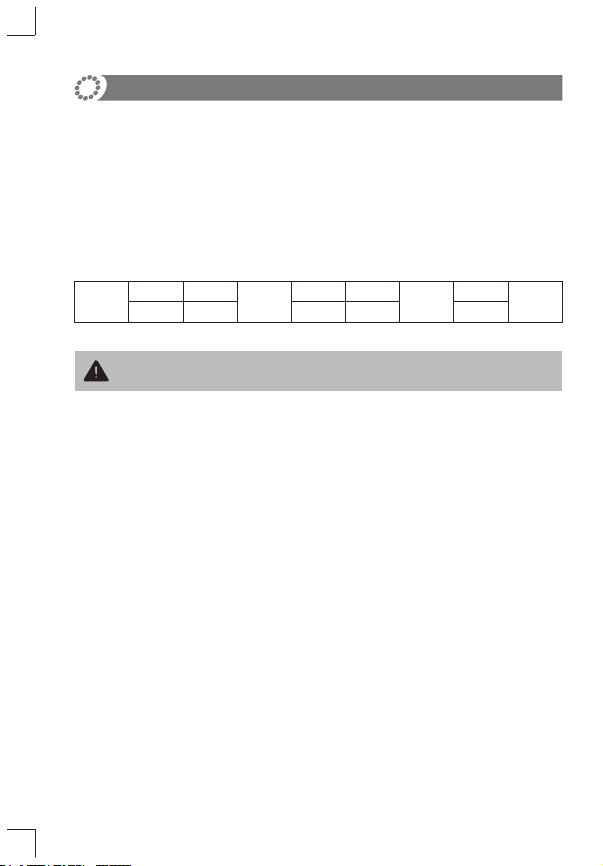
To avoid overheating and deteriorating the flash head, do not use stroboscopic flash
more than 10 times in succession.
Maximum Stroboscopic Flashes:
1/4
1/8
1/16
1/32
1/64
1/128
30
50
70
80
99
99
2
4
70
80
99
99
2
2
7
80
99
99
2
2
4
16
99
99
2
2
3
8
99
99
2
2
3
6
99
99
1
2
3
5
25
99
Flash Output
Hz 1 2 34567
1/4
1/8
1/16
1/32
1/64
1/128
1
2
2
5
15
99
1
2
2
4
10
99
1
2
2
4
6
99
1
2
2
3
6
99
1
2
2
3
5
99
1
2
2
3
5
36
1
2
2
3
5
20
Flash Output
Hz 9 10-11 12-13 13-15 15-19 20-998
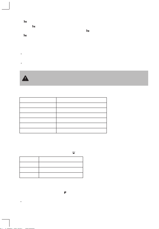
1/1 1/1-0.3 1/1-0.7 1/2 1/2-0.3 1/2-0.7 1/4
…
OF
1/2+0.7 1/2+0.3 1/4+0.7 1/4+0.3 …
Figures displayed when reducing flash output level→
←Figures displayed when increasing flash output level
Using the Flash
1. Power Management
2. Power Control
The flash output is adjustable from 1/1 full power to 1/128th power in 1/3rd step increments.
To obtain a correct flash exposure, use a hand-held flash meter to determine the required
flash output.
Press ON/OFF Power Switch for 2 seconds to power the ring flash on or off. Turn off if it will
not be used for an extended period of time.
Turn the select dial to adjust the flash output and the rules are shown in the following table:
Rotate Select Dial (20) to set a desired number.
A flash output of 1/1 or 1/2 cannot be set for stroboscopic flash.
Press the Mode Selection Button (16) so that “RPT” is displayed.
Press Set Button (17) to select the item to be set. The item blinks.
Calculating the Shutter Speed
During stroboscopic flash, the shutter remains open until the firing stops. Use the following
formula to calculate the shutter speed and set it with the camera.
Number of flashes / Firing frequency = Shutter speed
Stroboscopic flash is most effective with a highly reflective subject against a dark
background.
Using a tripod, a remote switch, and an external power source is recommended.
Stroboscopic flash can be used with “buLb”.
For example, if the number of flashes is 10 and the firing frequency is 5 Hz, the shutter
speed should be at least 2 sec.
Note:
of flashes, and the flash output.
For setting procedures, see the following: