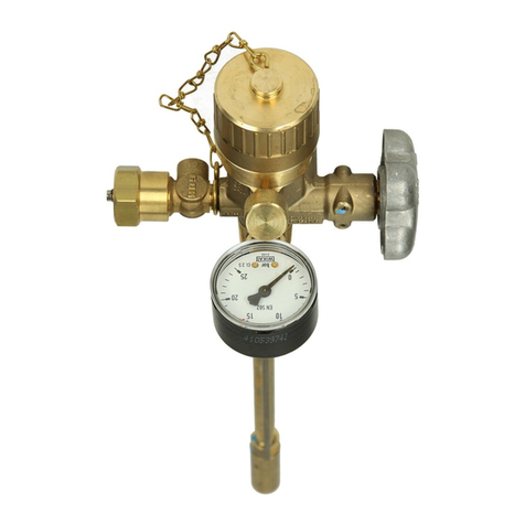
GOK CGV User manual

Originalanleitung / Artikel-Nr.09 737 50 dAusgabe 07.2017/Ersatz für Ausgabe 01.2016
Montage- und Bedienungsanleitung
Gasflaschenventil
Typ CGV für Propan-Flaschen
INHALTSVERZEICHNIS
ZU DIESER ANLEITUNG......................................................................................................................... 1
SICHERHEITSBEZOGENE HINWEISE ................................................................................................... 2
RODUKTBEZOGENE SICHERHEITSHINWEISE .................................................................................... 2
ALLGEMEINE PRODUKTINFORMATION ............................................................................................... 2
BESTIMMUNGSGEMÄSSE VERWENDUNG .......................................................................................... 3
NICHT BESTIMMUNGSGEMÄSSE VERWENDUNG............................................................................... 3
KENNZEICHNUNG.................................................................................................................................. 3
VORTEILE UND AUSSTATTUNG............................................................................................................ 4
ANSCHLÜSSE......................................................................................................................................... 4
MONTAGE............................................................................................................................................... 5
DICHTHEITSKONTROLLE ...................................................................................................................... 6
INBETRIEBNAHME ................................................................................................................................. 6
BEDIENUNG............................................................................................................................................ 6
WARTUNG .............................................................................................................................................. 6
AUSSERBETRIEBNAHME ...................................................................................................................... 7
ENTSORGEN .......................................................................................................................................... 7
TECHNISCHE DATEN............................................................................................................................. 7
LISTE DER ZUBEHÖRTEILE................................................................................................................... 7
GEWÄHRLEISTUNG ............................................................................................................................... 7
TECHNISCHE ÄNDERUNGEN................................................................................................................ 7
NOTIZEN ................................................................................................................................................. 8
ZU DIESER ANLEITUNG
•Diese Anleitung ist ein Teil des Produktes.
•Für den bestimmungsgemäßen Betrieb und zur Einhaltung der Gewährleistung
ist diese Anleitung zu beachten und dem Betreiber auszuhändigen.
•Während der gesamten Benutzung aufbewahren.
•Zusätzlich zu dieser Anleitung sind die nationalen Vorschriften, Gesetze und
Installationsrichtlinien zu beachten.
Gasflaschenventil
2 / 8
Artikel-Nr.09 737 50 d
SICHERHEITSBEZOGENE HINWEISE
Ihre Sicherheit und die Sicherheit anderer ist uns sehr wichtig. Wir haben viele wichtige
Sicherheitshinweise in dieser Montage- und Bedienungsanleitung zur Verfügung gestellt.
Lesen und beachten Sie alle Sicherheitshinweise sowie Hinweise.
Dies ist das Warnsymbol.Dieses Symbol warnt vor möglichen Gefahren, die den
Tod oder Verletzungen für Sie und andere zur Folge haben können. Alle
Sicherheitshinweise folgen dem Warnsymbol, auf dieses folgt entweder das
Wort "GEFAHR","WARNUNG" oder "VORSICHT".Diese Worte bedeuten:
bezeichnet eine Personengefährdung mit einem hohen Risikograd.
Hat Tod oder eine schwere Verletzung zur Folge.
bezeichnet eine Personengefährdung mit einem mittleren Risikograd.
Hat Tod oder eine schwere Verletzung zur Folge.
bezeichnet eine Personengefährdung mit einem niedrigen Risikograd.
Hat eine geringfügige oder mäßige Verletzung zur Folge.
bezeichnet einen Sachschaden.
Hat eine Beeinflussung auf den laufenden Betrieb.
RODUKTBEZOGENE SICHERHEITSHINWEISE
Ausströmendes Flüssiggas ist extrem entzündbar!
Kann zu Explosionen führen. Schwere Verbrennungen bei direktem Hautkontakt.
Verbindungen regelmäßig auf Dichtheit prüfen!
Bei Gasgeruch und Undichtheit Flüssiggasanlage sofort außer Betrieb nehmen!
Zündquellen oder elektrische Geräte außer Reichweite halten!
Entsprechende Gesetze und Verordnungen beachten!
Die Flüssiggasflasche muss während der Entnahme aufrecht stehen.
Ausschließlich aus der gasförmigen Phase entnehmen.
Die Gasflasche muss bei der Verwendung gegen Umfallen gesichert sein.
Gasflasche vor Überhitzung durch Strahlungs- und Heizungswärme schützen.
Einschlägige Installationsvorschriften der entsprechenden Länder beachten!
ALLGEMEINE PRODUKTINFORMATION
Das Sicherheitsflaschenventil CGV dient als Gasentnahmearmatur für die handelsüblichen,
ausschließlich mit Propan gefüllten, Aluminiumgasflaschen bis 2,7 kg Füllgewicht und einem
zulässigen Gesamtgewicht von 5 kg zum Anschluss von Gasverbrauchern mit
Kleinflaschenregler.
Das CGVist von Hand zu betätigen und entspricht den Anforderungen der ENISO 15995.
Zusätzlich ist das CGV mit einem Sicherheitsventil nach EN 13953 ausgestattet.

Gasflaschenventil
Artikel-Nr. 09 737 50 d3 / 8
BESTIMMUNGSGEMÄSSE VERWENDUNG
Betriebsmedium
•Propan
Einsatzbereich
•Campingbereich
•Caravans
•Motorcaravans
•Mobilheime
•Sportboote
Anforderungen an den Bediener
Der Bediener muss vor Gebrauch dieses Produktes die Montage- und Bedienungs-
anleitung aufmerksam gelesen haben.
NICHT BESTIMMUNGSGEMÄSSE VERWENDUNG
Jede Verwendung, die über die bestimmungsgemäße Verwendung hinausgeht:
•z. B. Betrieb mit anderen Medien, Drücken
•Verwendung von Gasen in der Flüssigphase
•Einbau entgegen der Durchflussrichtung
•Änderungen am Produkt oder an einem Teil des Produktes
KENNZEICHNUNG
Bedeutung der Kennzeichnung auf dem Gasflaschenventil Typ CGV
PRD
Kurzbezeichnung für das eingebaute Sicherheitsventil
G.3 bzw.
G.32
Bezeichnung des Anschlusses
an die Gasflasche
G.3: Art.-Nr. 09 737 00
G.32: Art.-Nr. 09 737 02
10.17Monat und Jahr der Herstellung (Beispiel: Oktober 2017)
CGV
Typbezeichnung Camping-Gasflaschen-Ventil
0,43 m³/min
Durchflussrate des Sicherheitsventils, in Kubikmeter Luft je Minute.
G.12
Bezeichnung des Anschlusses am Druckregelgerät
G.12
30 bar Nenneinstelldruck des Sicherheitsventiles

Gasflaschenventil
4 / 8
Artikel-Nr.09 737 50 d
VORTEILE UND AUSSTATTUNG
Eingangsanschluss an Gasflasche
Ausgangsanschluss
Sicherheitsventil mit roter Kunststoffkappe
Handrad
Beschriftung Gasart PROPAN
Pfeilrichtung AUF „+“ bzw. ZU „–“
Sicherheitsventil:
•selbstschließendes Druckentlastungsventil, das automatisch den Überdruck bei einem
voreingestellten Druck abbläst, wobei das Ventil schlagartig öffnet
•schließt selbsttätig, wenn der Druck wieder unterschritten wird
•die Einstellungen des Sicherheitsventils dürfen nicht verändert werden
•am Ausgang des Sicherheitsventils befindet sich eine rote Kunststoffkappe
Die rote Kunststoffkappe muss fest am Ausgang des Sicherheitsventils sitzen,
somit wird das Eindringen von Schmutz und Wasser zuverlässig verhindert.
Fehlt die rote Kunststoffkappe, ist es möglich, dass das Sicherheitsventil angesprochen hat.
ANSCHLÜSSE
Eingang
wahlweise
Handelsname und Abmessung nach Norm
Montagehinweis
Gewindeanschluss GAZ
•mit Dichtung NBR
•G.3 = Gewinde M 16 x 1,5-RH
Handfest anziehen!
Gewindeanschluss Primus
•G.32 = M14 x 1,5-RH
•Mit Dichtung NBR
Handfest anziehen!
Ausgang
Handelsname und Abmessung nach Norm
Montagehinweis
Außengewinde Kleinflaschenanschluss KLF
•Dichtung im Anschluß
•G.12 = Gewinde W 21,8 x 1/14-LH
Handfest anziehen!

Gasflaschenventil
Artikel-Nr.09 737 50 d
5 / 8
MONTAGE
Vor der Montage ist das Produkt auf Transportschäden und Vollständigkeit zu prüfen.
Alle nachfolgenden Hinweise dieser Montage- und Bedienungsanleitung müssen vom
Fachbetrieb und Betreiber beachtet, eingehalten und verstanden werden. Voraussetzung für
ein einwandfreies Funktionieren der Anlage ist eine fachgerechte Installation unter Beachtung
der für Planung, Bau und Betrieb der Gesamtanlage gültigen technischen Regeln.
Funktionsstörungen durch Rückstände!
Die ordnungsgemäße Funktion ist nicht gewährleistet.
Sichtkontrolle auf eventuelle Metallspäne oder sonstige Rückstände in den Anschlüssen
vornehmen!
Metallspäne oder sonstige Rückstände durch Ausblasen unbedingt entfernen!
•Dichtungen sauber und unbeschädigt einbauen.
•LH – Linksgewinde- Ausführung!
Schraubverbindungen
Explosions-, Brand- und Erstickungsgefahr durch Undichtheit der
Anschlüsse! Kann durch Verdrehen des Produktes zu Gasaustritt führen.
Produkt nach der Montage und beim Nachziehen der Anschlüsse nicht mehr verdrehen!
Nachziehen von Anschlüssen nur in vollständig drucklosem Zustand!
Verschlussmutter von der
Propan-Gasflasche entfernen
Gasflaschenventil Typ CGV an die
Propan-Gasflasche montieren
Schlauchleitung mit dem Druckregelgerät
verbinden
Druckregelgerät an Gasflaschenventil
Typ CGV montieren
RH
LH
LH

Gasflaschenventil
6 / 8
Artikel-Nr.09 737 50 d
DICHTHEITSKONTROLLE
Verbrennungs- oder Brandgefahr!
Schwere Hautverbrennungen oder Sachschaden.
Keine offenen Flammen zur Prüfung verwenden!
Dichtheitskontrolle vor Inbetriebnahme
Vor Inbetriebnahme sind die Anschlüsse des Produktes auf Dichtheit zu prüfen!
1. Alle Absperrarmaturen der angeschlossenen Verbraucher schließen.
2. Gasflaschenventil langsam öffnen.
3. Alle Anschlüsse mit schaumbildenden Mitteln nach EN 14291 (z. B. Lecksuchspray,
Bestell-Nr. 02 601 00) einsprühen.
Ammoniak, das in einigen Seifen und Reinigungsmitteln enthalten ist, greift
Messingarmaturen an.
Ammoniakhaltige Reinigungsmittel nicht für dieses Produkt verwenden!
4. Dichtigkeit prüfen, indem auf Blasenbildung im aufgesprühten,schaumbildenden Mittel
geachtet wird. Bilden sich weitere Blasen, müssen die Anschlüsse
nachgezogen werden (siehe MONTAGE). Falls sich die Undichtheiten nicht beseitigen
lassen, darf das Produkt nicht in Betrieb genommen werden.
INBETRIEBNAHME
Das Produkt ist nach MONTAGE und erfolgreicher DICHTHEITSKONTROLLE betriebsbereit.
BEDIENUNG
•Benutzen Sie dieses Produkt erst, nachdem Sie die Montage- und Bedienungs-
anleitung aufmerksam gelesen haben.
•Beachten Sie zu Ihrer Sicherheit alle Sicherheitshinweise dieser Montage- und
Bedienungsanleitung.
•Verhalten Sie sich verantwortungsvoll gegenüber anderen Personen.
Das Öffnen oder Schließen erfolgt durch Drehen des Handrades bis
Anschlag in Pfeilrichtung AUF „+“ oder ZU „-“.
WARTUNG
Das Produkt ist nach ordnungsgemäßer MONTAGE und BEDIENUNG wartungsfrei.
Ammoniak, das in einigen Seifen und Reinigungsmitteln enthalten ist, greift
Messingarmaturen an.
Messingarmaturen können nach Kontakt mit Ammoniak nach einigen Monaten Risse
bekommen und lecken.
Ammoniakhaltige Reinigungsmittel nicht für dieses Produkt verwenden!

Gasflaschenventil
Artikel-Nr.09 737 50 d
7 / 8
AUSSERBETRIEBNAHME
Alle freien Anschlüsse in den Zuleitungen der
Flüssiggasanlage sind mit einer geeigneten Verschlusskappe
dicht zu verschließen, um ausströmendes Gas zu vermeiden!
Das Gasflaschenventil zur Lagerung und zum
Transport der Propangasflasche entfernen, Verschlussmutter der
Propangasflasche fest eindrehen.
ENTSORGEN
Um die Umwelt zu schützen, dürfen unsere Produkte nicht mit dem Hausmüll
entsorgt werden.
Das Produkt ist über örtliche Sammelstellen oder Wertstoffhöfe zu entsorgen.
TECHNISCHE DATEN
Sicherheitsventil
(Angaben EN 13953)
Nenneinstelldruck
30 bar ± 15 %
Durchflussrate
0,43 m³/min Luft
Maximal zulässiger Druck
PS 16 bar
Gewicht
ca. 157 g
Gehäusewerkstoff
Messing (Werkstoff-Nr. CW617N)
Temperaturbereich
-20 °C bis +65 °C
LISTE DER ZUBEHÖRTEILE
Produktbezeichnung
Bestell-Nr.
Dichtung für KLF-Anschluss
10 071 22
Dichtung am Gewindeanschluss GAZ
20 015 29
Dichtung am Gewindeanschluss Primus
09 737 30
Verschlussmutter mit Befestigungslasche
55 300 95
Verschlussmutter ohne Befestigungslasche
55 300 90
GEWÄHRLEISTUNG
Wir gewähren für das Produkt die ordnungsgemäße Funktion und Dichtheit
innerhalb desgesetzlich vorgeschriebenen Zeitraums. Der Umfang unserer
Gewährleistung richtet sich nach § 8 unserer Liefer- und Zahlungsbedingungen.
TECHNISCHE ÄNDERUNGEN
Alle Angaben in dieser Montage- und Bedienungsanleitung sind die Ergebnisse der
Produktprüfung und entsprechen dem derzeitigen Kenntnisstand sowie dem Stand der
Gesetzgebung und der einschlägigen Normen zum Ausgabedatum. Änderungen der
technischen Daten, Druckfehler und Irrtümer vorbehalten. Alle Abbildungen dienen
illustrativen Zwecken und können von der tatsächlichen Ausführung abweichen.

Gasflaschenventil
Regler- und Armaturen-Gesellschaft mbH & Co. KG
Obernbreiter Straße 2-18 • 97340 Marktbreit / Germany
Tel.:+49 9332 404-0 • Fax: +49 9332 404-43
E-Mail: info@gok-online.de • Internet:www.gok-online.de
8 / 8
Artikel-Nr.09 737 50 d
NOTIZEN

Translation of original / Part No. 09 737 50 dVersion 07.2017/ Replaces version 01.2016
Assembly and operating instructions
Gas cylinder valve
type CGV for propane cylinders
CONTENTS
ABOUT THESE INSTRUCTIONS............................................................................................................. 1
SAFETY ADVICE..................................................................................................................................... 2
PRODUCT-RELATED SAFETY ADVICE ................................................................................................. 2
GENERAL PRODUCT INFORMATION .................................................................................................... 2
INTENDED USE ...................................................................................................................................... 3
INAPPROPRIATE USE............................................................................................................................ 3
INDENTIFICATION .................................................................................................................................. 3
ADVANTAGES AND EQUIPMENT .......................................................................................................... 4
CONNECTIONS....................................................................................................................................... 4
ASSEMBLY.............................................................................................................................................. 5
LEAK CHECK .......................................................................................................................................... 6
START-UP ............................................................................................................................................... 6
OPERATION............................................................................................................................................ 6
MAINTENANCE ....................................................................................................................................... 6
SHUT-DOWN........................................................................................................................................... 7
DISPOSAL ............................................................................................................................................... 7
TECHNICAL DATA .................................................................................................................................. 7
LIST OF ACCESSORIES ......................................................................................................................... 7
WARRANTY ............................................................................................................................................ 7
TECHNICAL CHANGES .......................................................................................................................... 7
NOTE....................................................................................................................................................... 8
ABOUT THESE INSTRUCTIONS
•These instructions are part of the product.
•These instructions must be observed and handed over to the operator to ensure
that the component operates as intended and to comply with the warranty terms.
•Keep them in a safe place while you are using the product.
•In addition to this manual, respect the national regulations, laws and installation
guidelines.

Gas cylinder valve
2 / 8
Part No. 09 737 50 d
SAFETY ADVICE
Your safety and the safety of others are very important. We have provided many important
safety messages in this manual and on your appliance.
Always read and obey all safety messages.
This is the safety alert symbol.
This symbol alerts you to potential hazards that can kill or hurt you and others.
All safety messages will follow the safety alert symbol and either the word
“DANGER”, “WARNING” or “CAUTION”. These words mean:
describes a personal hazard with a high degree of risk.
May result in death or serious injury.
describes a personal hazard with a medium degree of risk.
May result in death or serious injury.
describes a personal hazard with a low degree of risk.
May result in minor or moderate injury.
describes material damage.
Has an effect on ongoing operation.
PRODUCT-RELATED SAFETY ADVICE
Leaking LPG is extremely flammable!
Can cause explosion. Severe burns with direct contact to skin.
Check connections regularly for leaks!
In case of gas smell or leakage shut-down the installation immediately!
Keep ignition sources and electrical devices out of reach!
Observe applicable laws and regulations!
The LPG cylinder must be upright when gas is being withdrawn.
Gas is withdrawn only from the gaseous phase.
The gas cylinder must be secured so that it cannot topple over.
Protect gas cylinders against radiant heat or heat from heating appliances.
Observe the installation regulations in the respective countries.
GENERAL PRODUCT INFORMATION
The safety cylinder valve CGV isused as a gas withdrawal valve for aluminium alloy gas
cylinders; filled only with propane up to 2.7 kg filling weight and with a maximum
permissible weight of 5 kg for connection to gas appliances with small cylinder regulators.
The CGV isoperated manually and fulfils the requirements EN ISO 15995.
The CGV also has a safety valve in accordance with EN 13953.

Gas cylinder valve
Part No. 09 737 50 d
3 / 8
INTENDED USE
Operating media
•Propane
Area of application
•Camping
•Caravans
•Motorcaravans
•Mobile homes
•Sports boats
Requirements for the operator
Before using this product, the operator must read the assembly and installation
instructions carefully.
INAPPROPRIATE USE
All uses that are not appropriate:
•e.g. operating with different media, pressures
•Use of gases in the liquid phase
•Installation against the flow direction
•Changes to the product or parts of the product
INDENTIFICATION
Meaning of the labels on the gas cylinder valve type CGV
PRD
Abbreviation for the installed safety valve
G.3 bzw.
G.32
Description of the connection on
the cylinder
G.3: Part no. 09 737 00
G.32: Part no. 09 737 02
10.17
Month and year of manufacture
CGV Type description Camping Gas cylinder Valve
0,43 m³/min Flow rate of the safety valve, in cubic metres of air per minute
30 bar Nominal set pressure of the safety valve
G.12 Description of the connection to
the pressure regulator
G.12

Gas cylinder valve
4 / 8
Part No. 09 737 50 d
ADVANTAGES AND EQUIPMENT
Inlet connector on the gas cylinder
Outlet connection
Safety valve with red plastic cap
Handwheel
Label gas type PROPAN
Arrow direction OPEN „+“ or CLOSED „-“
Safety valve:
•self-closing pressure relief valve; when the set pressure is exceeded, the valve opens
automatically to relieve the pressure
•closes automatically when the pressure is below the set limit again
•the settings on the safety valve must not be changed
•there is a red plastic cap at the outlet of the safety valve
The red plastic cap must sit tightly on the outlet of the safety valve to prevent dirt
and water entering.
If the red plastic cap is missing, it is possible that the safety valve has been triggered.
CONNECTIONS
Inlet, optional
Trading name and dimensions
acc. to standard
Installation
instructions
GAZ thread connector
•with gasket NBR
•G.3 = Gewinde M 16 x 1.5-rh
Tighten hand-tight.
Primus thread connector
•G.32 = M14 x 1.5-rh
•with gasket NBR
Tighten hand-tight.
Outlet
Trading name and dimensions
acc. to standard
Installation
instructions
Male thread connector small cylinder KLF
•gasket in the connector
•G.12 = W 21.8 x 1/14-lh
Tighten hand-tight.

Gas cylinder valve
Part No. 09 737 50 d
5 / 8
ASSEMBLY
Before assembling, check that the product is complete and has not suffered any damage
during transport.
For the system to function as intended it must be installed professionally in compliance with
the technical instructions applicable to the planning, construction and operation of the entire
system.
Malfunctions caused by residues.
Proper functioning is not guaranteed.
Visually check that there are no metal filings or residues in the connections.
It is important that metal filings or other residues are blown out.
•Always install clean and undamaged gaskets.
•lh – left-hand thread version.
Screw connections
If connections leak, there is a danger of explosion, fire or suffocation.
Gas may escape if the product is turned.
Do not turn the product after it has been installed and the connections have been
tightened.
Tighten connections only when they are not pressurised.
Remove the seal from the propane
cylinder
Attach the gas cylinder valve type CGV to
the propane cylinder
Connect the hose to the pressure
regulator
Attach the pressure regulator to the gas
cylinder valve type CGV
rh
lh
lh

Gas cylinder valve
6 / 8
Part No. 09 737 50 d
LEAK CHECK
Risk of burning or fire
Serious burns to the skin or damage to property.
Do not use an open flame to check for leaks.
Leak check before start-up, check the product connections for leaks.
1. Close all shut-off fittings on the gas appliance.
2. Slowly open the withdrawal valve or the gas cylinder valve(s).
3. Spray all connections with a foam producing substance according to EN 14291
(e.g. leak spray, Part no. 02 601 00).
Ammonia, which is present in some soaps and cleaning products, is aggressive to
the brass fittings.
Do not use cleaning agents that contain ammonia for this product!
4. Bubbles will form in the foam producing substance if there are any leaks.
If bubbles form, tighten the connections (see ASSEMBLY). If you cannot stop the
leaks, the product must not be used.
START-UP
After the product has been assembled and the LEAK CHECK has been carried out
successfully, it is immediately ready for operation.
OPERATION
•Use this product only when you have read the assembly and installation instructions
carefully.
•For your own safety, observe all the safety information in these assembly and
installation instructions.
•Please also consider the safety of others.
Open or close the valve by turning the handwheel as far as it will go in the
arrow direction OPEN "+" or CLOSED "-".
MAINTENANCE
With proper assembly and operation, the product is maintenance free.
Ammonia, which is present in some soaps and cleaning products, is aggressive
to the brass fittings.
If brass fittings come into contact with ammonia, they can develop cracks and leak
after several months.
Do not use cleaning agents that contain ammonia for this product!

Gas cylinder valve
Part No. 09 737 50 d
7 / 8
SHUT-DOWN
Close all free connections in the feed lines of the LPG
system with suitable caps to prevent gas flowing out!
Remove the cylinder valve when you are transporting
and storing the propane cylinder, close the sealing nut of the
propane cylinder tightly.
DISPOSAL
To protect the environment, our products may not be disposed of along with
household waste.
The product must be disposed of via a local collection station or a recycling station.
TECHNICAL DATA
Safety valve
(Requirements EN 13953)
Nominal set pressure
30 bar ± 15 %
Flow rate
0.43 m³/min Luft
Max. admissible pressure
PS 16 bar
Weight
ca. 157 g
Housing material
Brass CW617N
Admissible temperature
-20 °C to +65 °C
LIST OF ACCESSORIES
Product description
Part no.
Gasket for KLF connection
10 071 22
Gasket on GAZ threaded connector
20 015 29
Gasket on Primus threaded connector
09 737 30
Sealing nut with fastening clip
55 300 95
Sealing nut without fastening clip
55 300 90
WARRANTY
We guarantee that the product will function as intended and will not leak
during the legally specified period. The scope of our warranty is based on
Section 8 of our terms and conditions of delivery and payment.
TECHNICAL CHANGES
All the information contained in these assembly and operating instructions is the result of
product testing and corresponds to the level of knowledge at the time of testing and the
relevant legislation and standards at the time of issue.
We reserve the right to make technical changes without prior notice. Errors and omissions
excepted. All figures are for illustration purposes only and may differ from actual designs.

Gas cylinder valve
Regler- und Armaturen-Gesellschaft mbH & Co. KG
Obernbreiter Straße 2-18 • 97340 Marktbreit / Germany
Tel.:+49 9332 404-0 • Fax: +49 9332 404-43
E-Mail: info@gok-online.de • Internet:www.gok-online.de
8 / 8
Part No. 09 737 50 d
NOTE
Other manuals for CGV
1
Table of contents
Languages:
Other GOK Control Unit manuals

GOK
GOK SBS User instructions

GOK
GOK Caramatic BasicTwo User instructions

GOK
GOK Caramatic Switch Two User instructions

GOK
GOK 02600 User manual

GOK
GOK CGV User instructions

GOK
GOK AUV PS 16 bar User instructions

GOK
GOK 0271 User instructions

GOK
GOK AUV PS 16 bar User instructions

GOK
GOK SBS User instructions

GOK
GOK AUV PS 16 User instructions