SHOWER ASSEMBLY
DUSCHSATZ
KIT DE DOUCHE
КОМПЛЕКТ ДЛЯ ДУША
CONJUNTO DE DUCHA
ZESTAW NATRYSKOWY
Instructions for assembly and use • Montage- und Gebrauchsanweisung • Notice technique montage et utilisation • Инcтрукция по монтажу и обслуживанию • Instrucción de Montaje y Servicio • Instrukcja Montażu i Obsługi
IOG 2335.00 Rev. 2 November 2008
10
GB D F RUS E PL
#GUARANTEE:
The guarantee conditions are contained on a separate sheet.
#IN THE EVENT OF A PROBLEM:
e-mail: graff@graff-mixers.com
#GARANTIE:
Les conditions de garantie se trouvent dans une feuille séparée.
#EN CAS DE PROBLEME:
e-mail: graff@graff-mixers.com
#GARANTÍA:
Las condiciones de la garantía se encuentran en otra hoja.
#EN CASO DE PROBLEMAS:
e-mail: graff@graff-mixers.com
#GARANTIE:
Die Gewährleistungsbedingungen sind auf dem separaten Blatt.
#SOLLTEN PROBLEME AUFTRETEN wenden Sie sich an uns
e-mail: graff@graff-mixers.com
#GWARANCJA:
Warunki gwarancji są zawarte na osobnej kartce.
#GDY POJAWI SIĘ PROBLEM:
e-mail: graff@graff-mixers.com
#ГАРАНТИЯ:
Гарантийные условия на отдельном листе.
#ЕСЛИ ВОЗНИКНЕТ ПРОБЛЕМА:
e-mail: graff@graff-mixers.com
GB D
FRUS
E PL
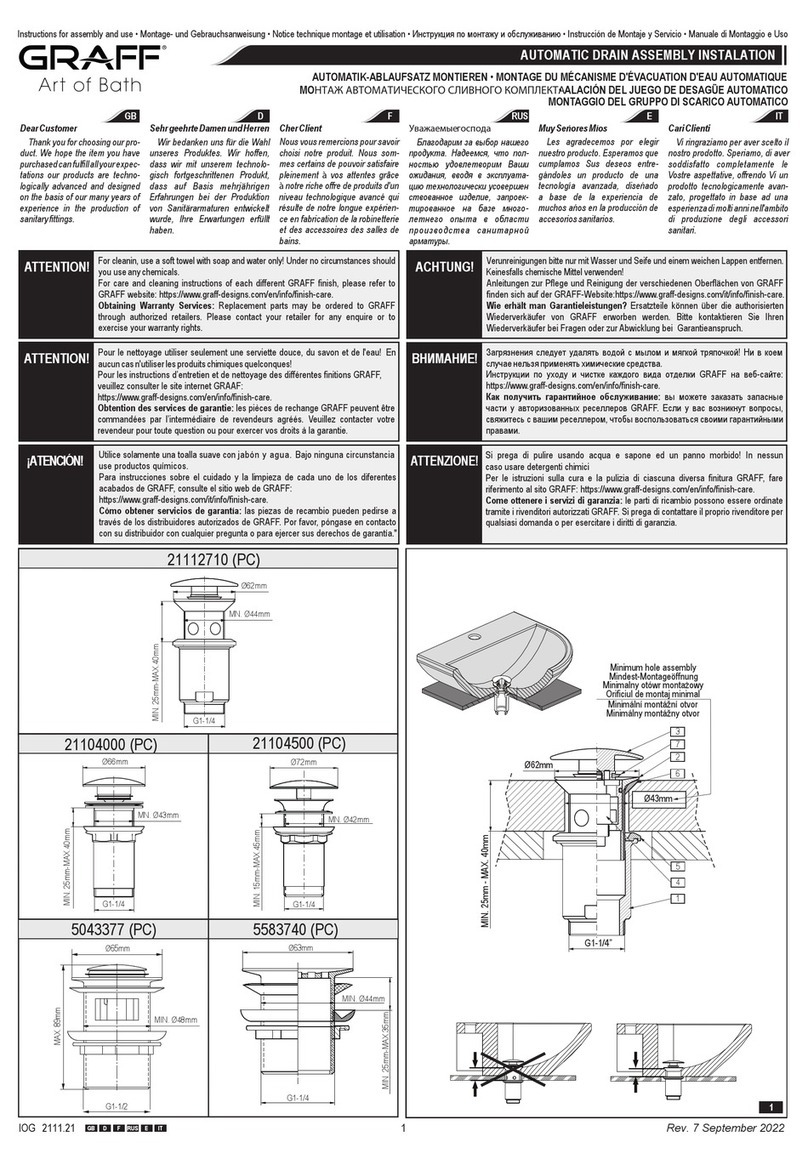
SHOWER ASSEMBLY
DUSCHSATZ
KIT DE DOUCHE
КОМПЛЕКТ ДЛЯ ДУША
CONJUNTO DE DUCHA
ZESTAW NATRYSKOWY
Instructions for assembly and use • Montage- und Gebrauchsanweisung • Notice technique montage et utilisation • Инcтрукция по монтажу и обслуживанию • Instrucción de Montaje y Servicio • Instrukcja Montażu i Obsługi
IOG 2335.00 Rev. 2 November 2008
2
GB D F RUS E PL
1
31
30
29
28
27
19
18
17
16
14
13
8
9
10
7
6
15
12
41
40
11
1
2
3
4
5
25
24
23
22 21
20
37
38
41
35
36
40
39
32
33
34
26
SHOWER ASSEMBLY
DUSCHSATZ
KIT DE DOUCHE
КОМПЛЕКТ ДЛЯ ДУША
CONJUNTO DE DUCHA
ZESTAW NATRYSKOWY
Instructions for assembly and use • Montage- und Gebrauchsanweisung • Notice technique montage et utilisation • Инcтрукция по монтажу и обслуживанию • Instrucción de Montaje y Servicio • Instrukcja Montażu i Obsługi
IOG 2335.00 Rev. 2 November 2008
3
GB D F RUS E PL
GB
D
FRUS E PL
1A
1
2
3
4
5
6
7
8
9
10
11A
11
12
13
14
15
16
17A
17
18
19
20
21
22
23
24
25
26
27
28
29
30
31
32
33
34
35
36
37
38
39
40
41
A
Shower body assembly
(complete)
Shower body
Mixer Ø40mm
Mixer nut
Decorative cap
Lever
Nut G3/4
Flat washer 24/16x2.8
Dog-leg connector
G3/4-G1/2
Rosette ring
Flat washer 24/16x2.8
Lower shower pipe section
Lower shower pipe
O-ring 14.3x2
Switch body
Connector
Slip ring (2 pcs.)
O-ring 17.3x2.4 (2 pcs.)
Upper shower pipe section
Upper shower pipe
O-ring 22x1.5
Support for arm
Clamp nut
Connector
Rosette ring
Washer for the rosette ring
Installation holder
Wall plug (2 pcs.)
Fixing screw (2 pcs.)
Follower ring
O-ring 21.8x1.7 (2 pcs.)
Locking nut
O-ring 17.3x2.4 (2 pcs.)
Shower arm
Connector G1/2 for shower
head
Flat washer
Shower head Ø200x13mm
Mounting point
Wall plug (2 pcs.)
Fixing screw (2 pcs.)
Decorative cap
Shower handset
Flat washer (2 pcs.)
Shower hose G1/2-1500mm
2.5 mm hexagon key
Duschkörper (komplett)
Duschkörper
Wassermischer Ø40mm
Mutter Wassermischer
Zierkappe
Hebel
Mutter G3/4
Flachdichtung 24/16x2.8
Exzenterverbinder
G3/4-G1/2
Rosette
Flachdichtung 24/16x2.8
Duscheinheit untere
Duschrohr unten
O-Ring-Dichtung 14.3x2
Umschalthebelkörper
Verbinder
Gleitring (2 Stk.)
O-Ring-Dichtung 17.3x2.4
(2 Stk.)
Duscheinheit obere
Duschrohr oben
O-Ring-Dichtung 22x1.5
Armbefestigung
Befestigungsmutter
Verbinder
Rosette
Rosettendichtung
Montagegriff
Spreizdübel (2 Stk.)
Montagenschraube (2 Stk.)
Druckring
O-Ring-Dichtung 21.8x1.7
(2 Stk.)
Druckmutter
O-Ring-Dichtung 17.3x2.4
(2 Stk.)
Duscharm
Anschluss der Überkopfbrause
G1/2
Flachdichtung
Überkopfbrause Ø200x13mm
Punkthalter
Spreizdübel (2 Stk.)
Montagenschraube (2 Stk.)
Verschlussscheibe
Handduschkopf
Flachdichtung (2 Stk.)
Duschschlauch G1/2-1500mm
Innensechskantschlüssel 2,5 mm
Colonne de douche (kit complet)
Colonne de douche
Mitigeur Ø40mm
Écrou du mitigeur
Capuchon décoratif
Levier
Écrou G3/4
Joint plat 24/16x2.8
Raccord excentré
G3/4-G1/2
Rosace
Joint plat 24/16x2.8
Partie basse de la douche
Tuyau de douche haut
Joint de type o-ring 14.3x2
Corps du commutateur
Raccord
Bague collectrice (quantité 2)
Joint de type o-ring 17.3x2.4
(quantité 2)
Partie haute de la douche
Tuyau de douche bas
Joint de type o-ring 22x1.5
Fixation du bras de douche
Écrou de fixation
Raccord
Rosace
Joint de la rosace
Point de montage
Cheville expansible (quantité 2)
Vis de montage (quantité 2)
Bague de serrage
Joint de type o-ring 21.8x1.7
(quantité 2)
Écrou de serrage
Joint de type o-ring 17.3x2.4
(quantité 2)
Bras de douche
Raccord G1/2 du pommeau de
douche
Joint plat
Tęte de douche Ø200x13mm
Support de fixation de la douche
Cheville expansible (quantité 2)
Vis de montage (quantité 2)
Cache
Pommeau de douche téléphone
Joint plat (quantité 2)
Tuyau de douche G1/2-1500mm
Clef Allen 2,5 mm
Koрпус душа компл. (комплект)
Корпус душевого крана
Смеситель Ø40мм
Гайка смесителя
Декоративный колпачок
Рукоятка крана
Гайка G3/4
Плоская прокладка 24/16x2.8
Эксцентриковый соединитель
G3/4-G1/2
Декоративный элемент
Плоская прокладка 24/16x2.8
Нижний душевой узел
Душевая труба нижняя
Уплотнение типа o-ring 14.3x2
Корпус переключателя
Соединитель
Контактное кольцо (2 шт.)
Уплотнение типа o-ring 17.3x2.4
(2 шт.)
Верхний душевой узел
Душевая труба верхняя
Уплотнение типа o-ring 22x1.5
Крепление кронштейна
Крепежная гайка
Соединитель
Декоративный элемент
Уплотнительная прокладка
декоративного элемента
Монтажный держатель
Распорный колышек (2 шт.)
Монтажный болт (2 шт.)
Прижимное кольцо
Уплотнение типа o-ring 21.8x1.7
(2 шт.)
Нажимная гайка
Уплотнение типа o-ring 17.3x2.4
(2 шт.)
Кронштейн душа
Присоединение G1/2 головки
душа
Плоская прокладка
Душевая головка Ø200x13мм
Настенный держатель
Распорный колышек (2 шт.)
Монтажный болт (2 шт.)
Заглушка
Ручной душ
Плоская прокладка (2 шт.)
Душевой шланг G1/2-1500мм
Шестигранный ключ 2,5мм
Cuerpo ducha juego (completo)
Cuerpo ducha
Mezclador Ø40mm
Tuerca mezclador
Caperuza ornamento
Palanca
Tuerca G3/4
Junta plana 24/16x2.8
Pieza de unión excéntrica
G3/4-G1/2
Roseta
Junta plana 24/16x2.8
Juego inferior de la ducha
Tubo inferior de la ducha
Junta tórica 14.3x2
Cuerpo del conmutador
Pieza de unión
Anillo deslizante (2 unidades)
Junta tórica 17.3x2.4 (2 unidades)
Juego superior de la ducha
Tubo superior de la ducha
Junta tórica 22x1.5
Sujeción brazo
Tuerca de sujeción
Pieza de unión
Roseta
Junta roseta
Mango de instalación
Pasador (2 unidades)
Tornillo de instalación (2 unidades)
Anillo de apriete
Junta tórica 21.8x1.7
(2 unidades)
Tuerca de apriete
Junta tórica 17.3x2.4
(2 unidades)
Brazo ducha
Racor G1/2 cabezal ducha
Junta plana
Cabezal ducha Ø200x13mm
Mango
Pasador (2 unidades)
Tornillo de instalación
(2 unidades)
Tapón
Auricular ducha
Junta plana (2 unidades)
Mangusto ducha G1/2-1500mm
La llave allén 2,5 mm
Korpus natrysku (kompletny)
Korpus natrysku
Mieszacz Ø40mm
Nakrętka mieszacza
Kołpak ozdobny
Dźwignia
Nakrętka G3/4
Uszczelka płaska 24/16x2.8
Łącznik mimośrodowy
G3/4-G1/2
Rozeta
Uszczelka płaska 24/16x2.8
Zespół natrysku dolny
Rura natrysku dolna
Uszczelka typu o-ring 14.3x2
Korpus przełącznika
Łącznik
Pierścień ślizgowy (2 szt.)
Uszczelka typu o-ring 17.3x2.4
(2 szt.)
Zespół natrysku górny
Rura natrysku górna
Uszczelka typu o-ring 22x1.5
Mocowanie ramienia
Nakrętka mocująca
Łącznik
Rozeta
Uszczelka rozety
Uchwyt montażowy
Kołek rozporowy (2 szt.)
Wkręt montażowy (2 szt.)
Pierścień dociskowy
Uszczelka typu o-ring 21.8x1.7
(2 szt.)
Nakrętka dociskowa
Uszczelka typu o-ring 17.3x2.4
(2 szt.)
Ramię natrysku
Przyłącze G1/2 węża natrysku
Uszczelka płaska
Głowica natryskowa
Ø200x13mm
Uchwyt punktowy
Kołek rozporowy (2 szt.)
Wkręt montażowy (2 szt.)
Zaślepka
Słuchawka natrysku
Uszczelka płaska (2 szt.)
Wąż natrysku G1/2-1500mm
Kluczyk imbusowy 2,5 mm
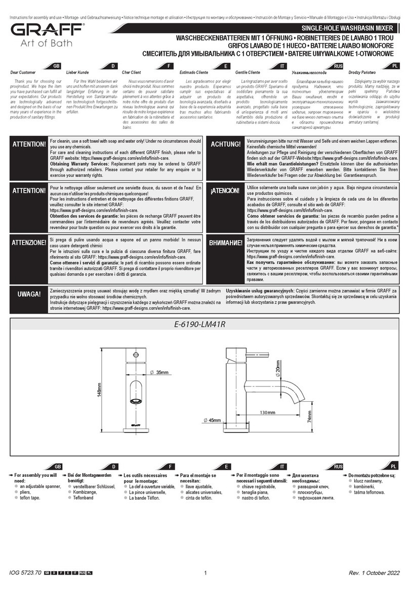
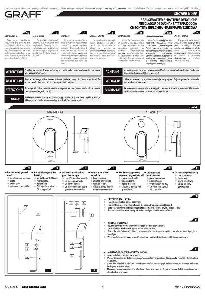
SHOWER BODY ASSEMBLY
See fig. 2.1-2.4
#The hot and cold water supply system should be installed and the mixer tap connected observing the following recommendations:
•the hot water coupling should be located on the right and the cold water coupling should be located on the left,
•coupling spacing: 150±21 mm,
•recommended installation height for the mixer tap: 900-1000 mm from the finished floor.
#Fit the dog-leg connectors (8) to the pipe sections where they exit the wall, first sealing them with teflon tape or other sealant, making sure that the dog-leg connector outlets are set at equal height with the end faces at
equal distances from the wall and that the distance between openings matches the distance between those of the connecting nuts (6) of the shower body (1A).
#Screw the rosette rings (9) onto the dog-leg connectors (8) until they touch the finished wall.
#Insert the gaskets (7) into the connecting nuts (6) and screw them onto the dog-leg connectors (8). Check the tightness of the connection after assembly.
GB
SHOWER ASSEMBLY
DUSCHSATZ
KIT DE DOUCHE
КОМПЛЕКТ ДЛЯ ДУША
CONJUNTO DE DUCHA
ZESTAW NATRYSKOWY
Instructions for assembly and use • Montage- und Gebrauchsanweisung • Notice technique montage et utilisation • Инcтрукция по монтажу и обслуживанию • Instrucción de Montaje y Servicio • Instrukcja Montażu i Obsługi
IOG 2335.00 GB D F RUS E PL
2.1 2.2 2.3 2.4
1A
1A
876
8
88
9
9
8
9
150±21mm
l Codwater
lsseKa twa r
u
Ea froide
ав
Холодня ода
Ag fr
ua ía
Zd
imna woa
watHot er
a ws
W rmwas er
E au
au ch de
ая д
Горяч во а
aatAgu c lien e
ł a
Ciep a wod
D
MONTAGE DES DUSCHKÖRPERS
Siehe Abb. 2.1-2.4
#Installieren Sie die Warm- und Kaltwasseranlage an der für die Batteriemontage vorgesehenen Stelle gemäß den unten genannten Hinweisen:
• der Warmwasseranschluss ist links und der Kaltwasseranschluss rechts an-zubringen,
• der Abstand der Anschlüsse sollte im Bereich: 150±21 mm liegen,
• die empfohlene Höhe der Batteriemontage sollte 900-1000 mm vom Fuß-bodenausbau betragen.
#In die mit dem Innengewinde G1/2” abgeschlossenen Strecken sind die Exzenter-verbinder (8) einzudrehen und die Verbindungen mit dem PTFE-Band (oder mit einem anderen Dichtmittel) abzudichten zu
beachten ist, dass die Öffnungsach-sen der Exzenter (8) von der Gewindeseite G3/4” auf derselben Höhe liegen, die Stirnflächen im gleichem Abstand von der Wand liegen, und der Öffnungsabstand dem Abstand
der Achsen der Anschlussmutter (6) des Duschkörpers (1A) ent-spricht.
#Rosetten (9) auf Exzenterverbinder (8) schrauben, bis sie an der Vorwand anlie-gen.
#In die Anschlussmuttern (6) Dichtungen (7) einlegen und sie auf die Exzenter-verbinder aufschrauben, nach der Montage die Verbindungen auf Dichtigkeit prü-fen.
MONTAŻ KORPUSU NATRYSKU
Zob. rys. 2.1-2.4
#Doprowadź instalację ciepłej i zimnej wody w miejsce montażu baterii zgodnie z zaleceniami:
•przyłącze wody ciepłej wykonaj po stronie lewej, przyłącze wody zimnej po prawej,
•rozstaw przyłączy musi się mieścić w zakresie: 150±21mm,
•zalecana wysokość montażu baterii: 900-1000mm od wykończonej podłogi.
#Do odcinków instalacji zakończonych gwintem wewnętrznym G1/2” wkręć łączniki mimośrodowe (8),
uszczelniając połączenia taśmą teflonową (lub innymi uszczelniaczami) - zwrócić uwagę na to, aby osie
otworów mimośrodów (8) od strony gwintu G3/4” były na jednej wysokości, powierzchnie czołowe w
jednakowej odległości od ściany, a odstęp otworów był równy odległości osi nakrętek przyłączeniowych
(6) korpusu natrysku (1A).
#Na łączniki mimośrodowe (8) nakręć rozety (9) do momentu, aż zetkną się one ze ścianą
wykończeniową.
#Włóż do nakrętek przyłączeniowych (6) uszczelki (7) i nakręcić je na łączniki mimośrodowe (8), po
zmontowaniu sprawdź szczelność połączeń.
MONTAGE DE LA COLONNE DE DOUCHE
Voire la figure 2.1-2.4
#Installez les arrivées d'eau chaude et d'eau froide ŕ l'emplacement oů vous souhaitez installez les
robinets, en respectant les consignes suivantes :
• la sortie d'eau chaude doit se trouver du côté gauche, celle d'eau froide du côté droit,
• la distance entre les deux sorties doit être comprise entre: 150±21 mm,
• il est conseillé de monter les robinets à une hauteur de: 900-1000 mm à partir du sol posé.
#Vissez les raccords excentrés (8) dans les segments de l'installation terminés par un filetage intérieur
G1/2”, en garnissant les raccords de bande en téflon (ou d'un autre produit assurant l'étanchéité)
vérifiez que les axes des orifices des raccords excentrés (8) situés du côté du filetage G3/4” se trouvent
ŕ hauteur identique, que les surfaces frontales sont ŕ distance égale du mur et que la distance entre les
orifices est égale ŕ la distance entre les axes des écrous de raccordement (6) de la colonne de douche
(1A).
#Vissez les rosaces (9) sur les raccords excentrés (8) jusqu'ŕ ce qu'elles viennent toucher le mur de
finition.
#Placez les joints (7) ŕ l'intérieur des écrous de raccordement (6) et vissez-les sur les raccords excentrés
(8); aprčs avoir effectué ce montage, vérifiez l'étanchéité des raccordements.
MOНТАЖ КОРПУСА ДУШЕВОГО КРАНА
См. рис. 2.1-2.4
#Подвести шланги для горячей и холодной воды к месту монтажа смесителя в соответствии с
указаниями:
•подсоединение горячей воды должно быть с левой стороны, подсоединение холодной воды с
правой стороны,
•расстояние между подсоединениями должно составлять не более 150±21мм,
•рекомендуется устанавливать смеситель на высоте 900-1000мм oт окончательного уровня
пола.
#На концы с внутренней резьбой G1/2”, ввинтите эксцентриковые соединители (8), уплотняя
соединение тефлоновой лентой (или другим уплотняющим материалом) обращайте внимание
на то, чтобы оси отверстий эксцентриков (8) со стороны резьбы G3/4” располагались на одной
высоте, торцевые поверхности на одинаковом расстоянии от стены, а расстояние между
отверстиями равнялось расстоянию между осями гаек (6) в корпусе смесителя (1A).
#Навинтите декоративный элемент (9) на эксцентриковые соединители (8) до момента
соприкосновения с отделанной стеной.
#Вложите в гайки (6) уплотнительные прокладки (7) и навинтите их на эксцентриковые
соединители (8), по окончании проверьте герметичность соединений.
INSTALACIÓN DEL CUERPO DE DUCHA
Ver figuras 2.1-2.4
#Conecte la instalación del agua caliente y fría al lugar de instalar la batería siguiendo las
recomendaciones:
•la acometida del agua caliente por el lado izquierdo, la acometida de la fría, por el derecho,
•la distancia ente las acometidas debe caber dentro de los límites: 150±21mm,
•la altura recomendada de la instalación de la batería: 900-1000mm sobre el nivel del suelo.
#En las secciones de la instalación acabadas con rosca interna G1/2” enrosque las piezas de unión
excéntricas (8), aislando las uniones con la cinta de teflón (u otro tipo de guarniciones) haga caso que
los ejes excéntricos (8) por el lado de la rosca G3/4” se encuentren en la misma altura, las superficies
frontales tengan la misma distancia de la pared, y el espacio entre los huecos sea igual que la distancia
entre los ejes de las tuercas (6) del cuerpo ducha (1A).
#En las piezas de unión excéntricas (8) enroscar las rosetas (9) hasta el momento que toquen la pared
#Meta dentro de las tuercas (6) las juntas (7) y enrósquelas en las piezas de unión excéntricas (8), tras
instalar compruebe la estanquidad de las uniones.
FRUS
EPL
SHOWER ASSEMBLY
DUSCHSATZ
KIT DE DOUCHE
КОМПЛЕКТ ДЛЯ ДУША
CONJUNTO DE DUCHA
ZESTAW NATRYSKOWY
Instructions for assembly and use • Montage- und Gebrauchsanweisung • Notice technique montage et utilisation • Инcтрукция по монтажу и обслуживанию • Instrucción de Montaje y Servicio • Instrukcja Montażu i Obsługi
IOG 2335.00 Rev. 2 November 2008
5
GB D F RUS E PL
40mm
3.1 3.2 3.3
SHOWER AND SHOWER HEAD ASSEMBLY
See fig. 3.1 - 3.4
#Screw the clamp nut of the lower shower pipe section (11A) onto the threaded connector pipe of the shower body (1A). Check if the flat washer (10) is positioned correctly. Position the lower section (11A) according to
fig. 3.1. Tighten the nut with the correct size wrench fitted with protective pads to avoid damage to the finishing of the cap.
#Slide the upper shower pipe section (17A) onto the lower shower pipe section (11A) connector (14). Do this carefully to avoid damage to the o-rings. Position the upper section (17A) correctly.
#Secure the installation holder (24) and screw the clamp nut (20) onto the connector of the holder. Place the installation holder (24) in the right position on the finished wall so the screw holes are both aligned
horizontally. Outline the contours of the holder (24) on the wall, as well as the screw holes.
#Hold the installation holder (24) and unscrew the clamp nut (20). Then remove the upper section of the shower (17A) from the connector (14). Put it somewhere safe to avoid damage.
#Drill the holes in the two places you marked with a pencil (6mm). Check if the distance between the holes conforms to fig. 3.2. Insert the wall plugs (25) into the holes. Fix the installation holder (24) to the walls with
fixing screws (26).
#Put the rosette ring (22) and the washer (23) onto the support (19).
#Mount the upper section of the shower (17A) back onto the connector (14). Be careful not to damage the o-rings. Position the upper section of the shower (17A) correctly.
#Screw the clamp nut (20) onto the installation holder (24). Push the rosette ring (22) with the washer (23) carefully onto the surface of the wall.
#Check if the shower arm (31) is set inside the support (19) at a minimum of 100mm - see fig. 3.4. To do this, loosen the locking nut (29) and retract the shower arm (31) from the support (19). Measure at least 100mm
from the end of the arm, then set it (31) into the support (19) at the distance required. Then tighten the locking screw (29).
#Screw the nut of the shower head (34) onto the connector (32) of the shower arm (31). Check if the flat washer (33) is positioned correctly in the nut of the head (34).
GB
31
17
14
14
13
11
10
1A
24
24
26
26
22
24
20
20
19
19
17A
17A
11A
17A
2xØ6mm
SHOWER ASSEMBLY
DUSCHSATZ
KIT DE DOUCHE
КОМПЛЕКТ ДЛЯ ДУША
CONJUNTO DE DUCHA
ZESTAW NATRYSKOWY
Instructions for assembly and use • Montage- und Gebrauchsanweisung • Notice technique montage et utilisation • Инcтрукция по монтажу и обслуживанию • Instrucción de Montaje y Servicio • Instrukcja Montażu i Obsługi
IOG 2335.00 Rev. 2 November 2008
6
GB D F RUS E PL
D
F
RUS
3.4
MONTAGE VON DUSCHSÄTZEN UND KÖPFEN
Siehe Abb. 3.1-3.4
#Befestigungsmutter der unteren Duscheinheit auf Gewindestutzen des Duschkörpers (1A) schrauben. Dabei korrekte
Lage der Flachdichtung (10) beachten. Nachdem die untere Einheit (11A) korrekt (gemäß Abb. 3.1) eingestellt ist,
Mutter festschrauben, dabei einen Universalschlüssel mit Sicherheitsauflagen gegen Verkleidungsflächenbe-
schädigung benutzen.
#Obere Duscheinheit (17A) vorsichtig auf den Verbinder (14) der unteren Duschein-heit schieben, dabei die O-Ringe
nicht beschädigen. Obere Duscheinheit (17A) lage-richtig einstellen.
#Befestigungsmutter (20) auf den Gewindestutzen des Montagegriffes (24) schrau-ben, dabei den Montagegriff
festhalten. Montagegriff (24) an der Vorwandfläche lage-richtig so einstellen, dass die 2 Montagebohrungen im
Montagegriff waagerecht fluch-ten. Umriss des Montagegriffes (24) und künftige Verdübelungspunkte mit einem
Bleistift markieren.
#Befestigungsmutter (20) abschrauben, dabei den Montagegriff (24) festhalten. An-schließend obere Duscheinheit
(17A) aus dem Verbinder (14) herausziehen und vor-sichtig an einen sicheren Platz legen.
#An den markierten Punkten mind. 2 Bohrungen ( 6 mm) herstellen, dabei sicherstel-len, dass der Bohrungsabstand der
Abb. 3.2 entspricht. Spreizdübel (25) einsetzen. Montagegriff (24) mit Schrauben (26) an der Wand befestigen.
#Rosette (22) mit Dichtung (23) auf Armbefestigung (19) schieben.
#Obere Duscheinheit (17A) wieder so auf den Verbinder (14) schieben, dass die O-Ringe nicht beschädigt werden.
Obere Duscheinheit (17A) lagerichtig einstellen.
#Befestigungsmutter (20) auf den Montagegriff (24) schrauben. Rosette (22) mit Dichtung (23) vorsichtig bis an die
Vorwandoberfläche schieben.
#Sicherstellen, dass der Duscharm (31) mind. 100 mm in die Armbefestigung (19) eingeschoben ist - siehe Abb. 3.4. Dazu
Druckmutter (29) lösen und den Duscharm (31) vorsichtig aus der Armbefestigung (19) ziehen. Mind. 100 mm vom
Armende messen und den Duscharm (31) in die Armbefestigung (19) in die gewünschte Tiefe schieben. Druckmutter
(29) festschrauben.
#Mutter des Duschkopfes (34) auf dem Anschluss (32) des Duscharmes (31) fest-schrauben. Dabei korrekte Lage der
Flachdichtung (33) in der Duschkopfmutter (34) beachten.
Ø
MONTAGE DES ÉLÉMENTS DE LA DOUCHE ET DE LA TĘTE DE DOUCHE
Voire la figure 3.1-3.4
#Vissez sur l'extrémité filetée de la colonne de douche (1A) l'écrou de fixation de la partie basse de la douche (11A).
Prenez bien soin de placer correctement le joint plat (10). Aprčs avoir placé la partie basse de la douche (11A) dans la
bonne position (conformément au schéma 3.1), vissez l'écrou, en utilisant une clef de montage avec protections
prévenant l'endommagement de la surface de finition.
#Enfilez avec précaution la partie haute de la douche (17A) sur le raccord (14) de la partie basse de la douche (11A) de
maničre ŕ ne pas endommager les étanchéités de type o-ring. Placez la partie supérieure de la douche (17A) dans la
bonne position.
#En tenant le point de montage (24), vissez ŕ son extrémité filetée l'écrou de fixation (20). Placez le point de montage (24)
dans la position adéquate sur le mur de pose, de façon ŕ ce que les deux orifices de montage soient alignés ŕ
l'horizontale. Marquez au crayon le contour extérieur du point de montage (24) et les points auxquels doivent ętre
placées les chevilles de montage.
#En tenant le point de montage (24), dévissez l'écrou de fixation (20). Ensuite, enlevez, en faisant glisser avec précaution
du raccord (14), la partie haute de la douche (17A). Déposez ce raccord ŕ un endroit oů il ne risque pas d'ętre
endommagé.
#Aux endroits marqués, percez au moins deux trous de diamčtre 6 mm, et vérifiez que l'écart entre les trous est
conforme au schéma 3.2. Placez les chevilles expansibles (25) dans ces orifices. Installez le point de montage (24) au
mur ŕ l'aide de vis (26).
#Placez la rosace (22) avec son joint (23) sur la fixation du bras de douche (19).
#Placez de nouveau sur le raccord (14) la partie haute de la douche (17A) en prenant bien soin de ne pas endommager
les étanchéités de type o-ring. Placez la partie haute de la douche (17A) dans la bonne position.
#Vissez sur le point de montage fixé (24) l'écrou de fixation (20). Rapprochez en faisant doucement glisser la rosace (22)
et son joint (23) vers la surface du mur d'installation.
#Assurez-vous que le bras de la douche (31) est glissé dans la fixation du bras (19) sur une distance d'au moins 100 mm -
voir schéma 3.4. Dans ce but, desserrez l'écrou de serrage (29) et sortez, en le faisant doucement glisser, le bras de la
douche (31) de sa fixation (19). Mesurez au moins 100 mm ŕ partir de l'extrémité du bras de douche et faites glisser ce
bras (31) dans sa fixation (19) de façon ŕ le placer ŕ la distance requise. Serrez l'écrou de serrage (29).
#Vissez l'écrou de la tęte de douche (34) sur le raccord (32) du bras de douche (31) et vissez l'écrou de la tęte de douche.
Prenez soin de placer correctement le joint plat (33) de l'écrou de la tęte de douche (34).
Ø
MОНТАЖ ДУШЕВОГО УЗЛА И ГОЛОВКИ
См. рис. 3.1-3.4
#На патрубок с резьбой на корпусе душевого крана (1A) навинтите гайку, закрепляющую нижний душевой узел (11A). Обращайте внимание на правильное положение плоской прокладки (10). После
установки нижнего душевого узла (11A) в нужном положении (согл. рис. 3.1) затяните гайку, используя разводной ключ с предохранительными накладками, защищающими поверхности от повреждения.
#На соединитель (14) нижнего душевого узла (11A) осторожно наденьте верхний душевой узел (17A) таким образом, чтобы не повредить уплотнение o-ring. Установите верхний душевой узел (17A) в
нужном положении.
#Придерживая монтажный держатель (24), навинтите на его конец с резьбой крепежную гайку (20). Установите монтажный держатель (24) в нужном положении на поверхности стены так, чтобы 2
монтажных отверстия в держателе оказались на одной линии по горизонтали. Разметьте карандашом наружный контур держателя (24) и пункты под распорные колышки.
#Придерживая монтажный держатель (24), oтвинтите крепежную гайку (20). Затем осторожно снимите с соединителя (14) верхний душевой узел (17A) и отложите осторожно в безопасное место.
#В обозначенных местах высверлите мин. 2 oтверстия 6мм. Убедитесь, что расстояние между отверстиями отвечает рис. 3.2. Вставьте распорные колышки (25) в отверстия. С помощью монтажных
болтов (26) прикрепите монтажный держатель (24) к стене.
#Наденьте декоративный элемент (22) с уплотнительной прокладкой (23) на крепление кронштейна (19).
#Снова наденьте верхний душевой узел (17A) на соединитель (14) таким образом, чтобы не повредить уплотнение o-ring. Установите верхний душевой узел (17A) в нужном положении.
#Навинтите крепежную гайку (20) на закрепленный монтажный держатель (24). Осторожно передвиньте декоративный элемент (22) с уплотнительной прокладкой (23) к поверхности отделанной стены.
#Убедитесь, что кронштейн душа (31) вставлен в крепление кронштейна (19) на глубину мин. 100 мм - см. рис. 3.4. Для этого ослабьте нажимную гайку (29) и осторожно извлеките кронштейн душа (31) из
крепления кронштейна (19). Oтмерьте мин. 100 мм от конца кронштейна и вставьте кронштейн душа (31) в крепление (19) на необходимую глубину. Затяните нажимную гайку (29).
#На присоединение (32) к кронштейну душа (31) навинтите гайку душевой головки (34). Обращайте внимание на правильное положение плоской уплотнительной прокладки (33) в гайке головки (34).
Ø
MIN. 100mm
22 29
19
31
32
33
34
31
17A
SHOWER ASSEMBLY
DUSCHSATZ
KIT DE DOUCHE
КОМПЛЕКТ ДЛЯ ДУША
CONJUNTO DE DUCHA
ZESTAW NATRYSKOWY
Instructions for assembly and use • Montage- und Gebrauchsanweisung • Notice technique montage et utilisation • Инcтрукция по монтажу и обслуживанию • Instrucción de Montaje y Servicio • Instrukcja Montażu i Obsługi
IOG 2335.00 Rev. 2 November 2008
7
GB D F RUS E PL
D
MONTAŻ ZESPOŁÓW NATRYSKU I GŁOWICY
Zob. rys. 3.1-3.4
#Na króciec gwintowany korpusu natrysku (1A) nakręć nakrętkę mocującą zespół dolny natrysku (11A). Zwróć uwagę na prawidłowe
ułożenie uszczelki płaskiej (10). Po ustawieniu dolnego zespołu (11A) we właściwej pozycji (zgodnie z rys. 3.1) dokręć nakrętkę,
używając klucza nastawnego z nakładkami zabezpieczającymi przed zniszczeniem powierzchni wykończeniowej.
#Na łącznik (14) dolnego zespołu natrysku (11A) ostrożnie nasuń górny zespół natrysku (17A) w taki sposób, aby nie uszkodzić
uszczelnień typu o-ring. Ustaw górny zespół natrysku (17A) we właściwej pozycji.
#Przytrzymując uchwyt montażowy (24) nakręć na jego króciec gwintowany nakrętkę mocującą (20). Ustaw uchwyt montażowy (24)
we właściwej pozycji na powierzchni ściany wykończeniowej tak, aby 2 otwory montażowe w uchwycie były ustawione w jednej linii w
poziomie. Odznacz ołówkiem obrys zewnętrzny uchwytu (24) i punkty na kołki montażowe.
#Przytrzymując uchwyt montażowy (24) odkręć nakrętkę mocującą (20). Następnie wysuń ostrożnie z łącznika (14) górny zespół
natrysku (17A). Odłóż go ostrożnie na w bezpieczne miejsce.
#W miejscach zaznaczonych wywierć min. 2 otwory 6mm, upewnij się, że rozstaw otworów jest zgodny z rys. 3.2. Umieść kołki
rozporowe (25) w otworach. Przymocuj uchwyt montażowy (24) do ściany wkrętami (26).
#Nasuń rozetę (22) z uszczelką (23) na mocowanie ramienia (19).
#Ponownie na łącznik (14) nasuń górny zespół natrysku (17A) w taki sposób, aby nie uszkodzić uszczelnień typu o-ring. Ustaw górny
zespół natrysku (17A) we właściwej pozycji.
#Na zamocowany uchwyt montażowy (24) nakręć nakrętkę mocującą (20). Ostrożnie dosuń rozetę (22) z uszczelką (23) do
powierzchni ściany wykończeniowej.
#Upewnij się, że ramię natrysku (31) jest wsunięte w mocowanie ramienia (19) na odległość min. 100mm - zob. rys. 3.4. W tym celu
poluzuj nakrętkę dociskową (29) i wysuń ostrożnie ramię natrysku (31) z mocowania ramienia (19). Odmierz min. 100mm od końca
ramienia i wsuń ramię (31) w mocowanie (19) na wymaganą odległość. Dokręć nakrętkę dociskową (29).
#Na przyłącze (32) w ramieniu natrysku (31) nakręć nakrętkę głowicy natryskowej (34). Zwróć uwagę na poprawne ułożenie uszczelki
płaskiej (33) w nakrętce głowicy (34).
MONTAGE DES DUSCHSATZES MIT PUNKTHALTER
Siehe Abb. 4
#2 Bohrungen ( 6 mm) rechts der Duschbatterie in der entsprechenden Höhe herstel-len und Spreizdübel (36) einsetzen.
#Punkthalter (35) mit Schrauben (37) an der Wand befestigen. Zierverschlussscheibe (38) aufsetzen.
#Eine Mutter des Duschschlauches (41) auf den Anschluss im Umschalthebelkörper (13) schrauben. Zweite konische Mutter des
Duschschlauches auf den Stutzen des Handduschkopfes (39) schrauben. Dabei Flachdichtungen (40) in beide Dusch-
schlauchmuttern einlegen.
#Handduschkopf (39) in den Punkthalter (35) einsetzen.
Ø
INSTALACIÓN DE LOS JUEGOS DUCHA Y CABEZAL
Ver figuras 3.1-3.4
#En el racor roscado del cuerpo ducha (1A) enrosque la tuerca que sujeta el juego inferior de la ducha (11A). Fíjese en la posición adecuada de la junta plana (10). Tras posicionar el juego inferior (11A) en la posición
adecuada (según la figura 3.1), apriete la tuerca usando la llave inglesa con las tuercas que protegen la superficie de acabado.
#En la pieza de unión (14) del juego interior de la ducha (11A) meta con cuidado el juego superior de la ducha (17A) de tal modo que no se dañen las juntas tóricas. Coloque el juego superior de la ducha (17A) en la
posición adecuada.
#Sujetando el mango de instalación (24) enrosque en su racor roscado la tuerca de sujeción (20). Coloque el mango de instalación (24) en la posición adecuada en la superficie de la pared de acabado de tal modo que
2 huecos de instalación en el mango se encuentren en la misma línea horizontal. Marque con el lápiz la forma externa del mango (24) y dos puntos para los pasadores.
#Sujetando el mango de instalación (24) desenrosque la tuerca de sujeción (20). Luego saque con cuidado el juego superior de la ducha (17A) de la pieza de unión (14). Póngalo con cuidado en algún sitio seguro.
#En los puntos marcados taladre 2 huecos de 6mm, asegúrese de que la distancia entre los huecos está conforme con la figura 3.2. Coloque los pasadores (25) en los huecos. Sujete el mango de instalación (24) a la
pared usando los tornillos (26).
#Meta la roseta (22) con la junta (23) en la sujeción del brazo (19).
#Vuelva a meter en la pieza de unión (14) el juego superior de la ducha (17A) de tal modo que no se dañen las juntas tóricas. Coloque el juego superior de la ducha (17A) en la posición adecuada.
#En el mango de instalación montado (24) enrosque la tuerca de sujeción (20). Apriete con cuidado la roseta (22) con la junta (23) contra la pared de acabado.
#Asegúrese que el brazo de la ducha (31) está metido en la sujeción del brazo (19) a la distancia mínima de 100mm - ver la figura 3.4. Para este fin suelte un poco la tuerca de apriete (29) y saque con cuidado el brazo de
la ducha (31) de la sujeción del mismo (19). Mida como mínimo 100mm desde el extremo del brazo y meta el brazo (31) en la sujeción (19) a la distancia requerida. Enrosque la tuerca de apriete (29).
#En el racor (32) situado en el brazo de la ducha (31) enrosque la tierca del cabezal ducha (34). Fíjese en la posición adecuada de la junta plana (33) en la tuerca del cabezal (34).
SHOWER ASSEMBLY WITH MOUNTING POINT
See fig. 4
#Drill two holes ( 6mm) to the right of the shower mixing tap at the required height and insert the wall plugs (36).
#Fix the mounting point (35) onto the wall using screws (37). Cover with the decorative cap (38).
#Screw the shower hose nut (41) onto the connector in the switch body (13). Screw the second conic shower hose nut onto the handset
connector pipe (39). Remember to fit the flat washer (40) inside the both nuts of the shower hose.
#Place the handset (39) on the mounting point (35).
Ø
MONTAGE DU KIT DE DOUCHE AVEC POINT DE FIXATION UNIQUE
Voire la figure 4
#Percez deux orifices de diamètre 6 mm du côté droit de la robinetterie de la douche, à la hauteur requise, et placez à l'intérieur les
chevilles expansibles (36).
#Fixez le point de support de fixation de la douche (35) au mur à l'aide de vis (37). Mettez le cache décoratif (38).
#Vissez l'écrou du tuyau de la douche (41) sur le raccord du corps du commutateur (13). Vissez le second écrou (conique) du tuyau de
douche sur l'extrémité du pommeau de douche téléphone (39). N'oubliez pas de placer les joints plats (40) dans les deux écrous du
tuyau de douche.
#Placez le pommeau de la douche (39) sur son support de fixation (35).
Ø
F
E
PL
GB
4
13
41
40
39
40
41
38
35
36
37
SHOWER ASSEMBLY
DUSCHSATZ
KIT DE DOUCHE
КОМПЛЕКТ ДЛЯ ДУША
CONJUNTO DE DUCHA
ZESTAW NATRYSKOWY
Instructions for assembly and use • Montage- und Gebrauchsanweisung • Notice technique montage et utilisation • Инcтрукция по монтажу и обслуживанию • Instrucción de Montaje y Servicio • Instrukcja Montażu i Obsługi
IOG 2335.00 Rev. 2 November 2008
8
GB D F RUS E PL
D
OБСЛУЖИВАНИЕ
См. рис.
#Подача воды и плавное регулирование интенсивности струи осуществляется путем отклонения
рукоятки крана вверх (макс. на 25 ). Oпуская рукоятку, закрываем подачу воды.
#Температуру воды увеличиваем, поворачивая рукоятку крана влево, а уменьшаем -
поворачивая вправо. В крайнем левом положении течет только горячая вода, в крайнем правом -
только холодная.
#Переключающий клапан предназначен для выбора режима работы: поворотом рукоятки крана
вправо направляем струю воды в душевую головку, поворачивая влево, направляем струю воды
в ручной душ.
5.1-5.2, 6.1-6.2
º
OPERATION
See fig. 5.1-5.2, 6.1-6.2
Lifting the lever will turn on the water and increase the flow (max. by 25º). Lowering the handle reduces
and then turns off the water flow.
The temperature can be increased by moving the lever to the left, and reduced by moving it to the right.
The extreme left position of the holder gives hot water only, while the extreme right position gives cold
water only.
The selection valve is used to select either the main shower head or the handset. Move the handle to the
right to use the main shower head and move the handle to the left to use the shower handset.
#
#
#
BEDIENUNGSABLAUF
Siehe Abb.
#Das Öffnen des Wasserauslaufs und die stufenlose Einstellung des auslaufenden Wassers erfolgen
mittels Stellung des Griffes nach oben (um max. 25º). Die Senkung des Griffes schließt den
Wasserstrom ab.
#Durch Drehen des Griffs nach links wird die Wassertemperatur erhöht; durch Drehen des Griffs nach
rechts wird die Wassertemperatur gesenkt. Die linke Endstellung des Griffs verursacht den Austritt von
ausschließlich heißem Wasser, die rechte Endstellung von ausschließlich kaltem Wasser.
#Der Brauseumschalter dient zur Auswahl der Arbeitsmodi: das Stellen des Hebels nach rechts
verursacht einen Wasserstrom direkt aus der Überkopfbrause, das Stellen des Hebels nach links
verursacht einen Wasserstrom aus dem Hand-duschkopf.
5.1-5.2, 6.1-6.2
MODE D'EMPLOI
Voire la figure
#Pour ouvrir l'arrivée d'eau et pour régler son débit, vous inclinerez la poignée du robinet vers le haut
(sous un angle maximum de 25 ). L'abaissement de cette poignée coupera l'arrivée d'eau.
#Pour augmenter la température de l'eau, vous tournerez la poignée du robinet vers la gauche ; de la
męme façon, pour faire baisser la température de l'eau, vous tournerez la poignée vers la droite. Si vous
tournez la poignée du robinet jusqu'au bout vers la gauche, seule de l'eau chaude sortira de la douche.
Si, au contraire, vous la tournez jusqu'au bout vers la droite, seule de l'eau froide s'écoulera.
#Le robinet-commutateur sert ŕ sélectionner le mode de fonctionnement de la douche: en tournant le
levier vers la droite, on actionne la sortie de l'eau de la tęte de douche; en le tournant vers la gauche,
l'eau sort du pommeau de douche (téléphone).
5.1-5.2, 6.1-6.2
º
INSTALACIÓN DEL JUEGO DUCHA CON EL MANGO ÚNICO
Ver la figura 4
#Por el lado derecho de la batería ducha taladre 2 huecos de 6 mm en la altura correspondiente y meta
dentro los pasadores (36).
#Fije el mango único (35) en la pared mediante los tornillos (37). Ponga el tapón ornamento (38).
#Enrosque la tuerca del manguito de ducha (41) en el racor situado en el cuerpo del conmutador (13).
Enrosque la otra tuerca (cónica) del manguito en el racor del auricular de ducha (39). Recuerde poner
las juntas planas (40) en ambas tuercas del manguito de ducha.
#Coloque el auricular de ducha (39) en el mango único (35).
Ø
MOНТАЖ ДУШЕВОГО КОМПЛЕКТА С НАСТЕННЫМ ДЕРЖАТЕЛЕМ
См. рис. 4
#С правой стороны душевого смесителя, на нужной высоте необходимо высверлить 2 отверстия 6мм и вставить в них распорные колышки (36).
#С помощью болтов (37) прикрепите к стене настенный держатель (35). Вставьте декоративную заглушку (38).
#Навинтите гайку душевого шланга (41) на присоединение в корпусе переключателя (13). Вторую конусную гайку на душевом шланге навинтите на конец ручного душа (39). Не забудьте проложить
плоские уплотнительные прокладки (40) в обеих гайках душевого шланга.
#Поместите ручной душ (39) в настенный держатель (35).
Ø
MONTAŻ ZESTAWU NATRYSKOWEGO Z UCHWYTEM PUNKTOWYM
Zob. rys. 4
#Po prawej stronie baterii natryskowej wywierć 2 otwory 6mm na odpowiedniej wysokości i włóż w nie
kołki rozporowe (36).
#Przymocuj uchwyt punktowy (35) do ściany wkrętami (37). Załóż zaślepkę ozdobną (38).
#Nakręć nakrętkę węża natrysku (41) na przyłącze w korpusie przełącznika (13). Drugą nakrętkę
(stożkową) węża natrysku nakręć na króciec słuchawki natryskowej (39). Pamiętaj o założeniu
uszczelek płaskich (40) do obydwu nakrętek węża natrysku.
#Umieść słuchawkę natryskową (39) w uchwycie punktowym (35).
Ø
FRUS
RUS
E PL
GB
5.1
5.2 6.1 6.2
Close Position
Geschlossen
Fermé
Закрыто
Cerrado
Zamknięte
Open Position
Geöffnet
Ouvert
Oткрыто
Abierto
Otwarte
25°
90°
Hot water
Warmwaswser
Eau chaude
Горячая вода
Agua caliente
Ciepła woda
Cold water
Kaltwasser
Eau froide
Холодная вода
Agua fría
Zimna woda
SHOWER ASSEMBLY
DUSCHSATZ
KIT DE DOUCHE
КОМПЛЕКТ ДЛЯ ДУША
CONJUNTO DE DUCHA
ZESTAW NATRYSKOWY
Instructions for assembly and use • Montage- und Gebrauchsanweisung • Notice technique montage et utilisation • Инcтрукция по монтажу и обслуживанию • Instrucción de Montaje y Servicio • Instrukcja Montażu i Obsługi
IOG 2335.00 Rev. 2 November 2008
9
GB D F RUS E PL
OBSŁUGA
Zob. rys. 5.1-5.2, 6.1-6.2
#Otwarcie wypływu wody oraz płynna regulacja jej wydatku następuje w wyniku wychylenia uchwytu do
góry (o max kąt 25 ). Opuszczenie uchwytu powoduje zamknięcie wypływu wody.
#Zwiększenie temperatury wody następuje przez obrót uchwytu w lewo, a zmniejszenie przez obrót
uchwytu w prawo. Skrajne lewe położenie uchwytu daje wypływ tylko wody gorącej, skrajne prawe -
wypływ tylko wody zimnej
#Zawór przełączający jest przeznaczony do wyboru trybu pracy: obrót dźwigni w prawo powoduje
wypływ wody przez głowicę natrysku, obrót dźwigni w lewo powoduje wypływ wody przez słuchawkę
natryskową.
º
MANEJO
Ver figuras
#Abrir la salida del agua y el ajuste de su chorro se realiza tras mover el mando hacia arriba (por el ángulo
máx. de 25 ). Bajar el mando causa el cierre de la salida del agua.
#Aumentar la temperatura se realiza tras mover el mando hacia izquierda, reducir la temperatura, hacia
derecha. La posición extrema izquierda nos da sólo el agua caliente, la posición extrema derecha, sólo
el agua fría.
#La válvula de conmutación sirve para escoger el modo de trabajo: girar la palanca hacia derecha causa
la salida del agua a través del cabezal de ducha, girar la palanca hacia izquierda, a través del auricular
de ducha.
5.1-5.2, 6.1-6.2
º
EPL
#MAINTENANCE
Clean water guarantees that a mixer equipped with ceramic flow regulators will work correctly, i.e. th
water should not contain any impurities such as sand, boiler scale etc. Because of this, the pipe system
should be equipped with sieve filters or, if there is no such possibility, with individual cut-off valves with
filters designed for such mixers.
In the event of increased steering resistance, greater pressure should not be exerted on the handle, as
this may cause damage to the flow regulator. In such a situation, the regulator should be removed and
cleaned of the dirt and impurities which have accumulated on it.
The seals should be maintained with vaseline or silicon oil.
Cleaning the outer coating:
dirt or stains on the external surfaces of the mixer resulting from scale deposits should be removed by
washing the unit with soapy water only. Scale deposits should be dissolved with vinegar then the surface
rinsed with clean water and rubbed dry with a soft cloth,
under no circumstances should the surface of the mixer be cleaned with coarse cloths or cleaning
agents containing abrasive materials or acids, plastic or lacquered parts must not be cleaned with
chemicals containing alcohol, disinfectants or solvents.
l
l
l
l
l
#КОНСЕРВИРОВАНИЕ
Гарантией правильной работы смесителей, оснащенных керамическими регуляторами
протекания, является чистая вода, т.е. которая не содержит таких загрязнений, как : песок,
накипь, и т.п. В связи с вышесказанным, требуется оснащение водопроводной системы
сетчатыми фильтрами, а если это невозможно, индивидуальными запорными клапанами
с фильтром, предназначенными для смесителей.
В случае повышенного сопротивления при регулировании запрещается увеличивать силу
нажима на рычаг, т.к. это может привести к повреждению регулятора протекания. В этой
ситуации необходимо демонтировать регулятор и очистить его от загрязнений.
Уплотнения консервировать вазелином или силиконовым маслом.
Очистка наружных поверхностей:
загрязнение или пятна, возникшие в результате оседания камня на внешних поверхностях
смесителя, смывать исключительно водой с мылом, для растворения камня применять уксус,
затем промыть поверхность чистой водой и досуха вытереть мягкой тряпочкой,
ни в каком случае нельзя чистить поверхность смесителя шероховатыми тряпочками или
чистящими средствами с содержанием абразивных компонентов и кислот,
для чистки элементов, выполненных из пластмассы или лакированных, запрещается
использовать средства, содержащие алкоголь, дезинфицирующие средства или растворители.
l
l
l
l
l
l
#WARTUNG
Eine Garantie für richtige Funktion von Batterien mit keramischen Durchflussregler ist sauberes
Wasser, dass heißt Wasser ohne solche Verunreinigungen, wie: Sand, Kesselstein, usw. Deswegen
wird die Ausrüstung der Wasserleitungsanlage mit Gitterfilter gefordert, und wenn solche Filter nicht
vorhanden sind, soll es möglich sein, die für Batterien bestimmte Absperrventile mit Filter zu montieren.
Bei vergrößertem Einstellungswiderstand soll man auf den Heben keinen größeren Druck ausüben, da
es eine Beschädigung des Durchflussreglers verursachen kann. Wenn es so ist, soll man den Regler
ausmontieren und die auf dem Regler gesammelten Verunreinigungen entfernen.
Die Dichtungen sollen mit Vaselin oder Silikonöl gewartet werden.
Reinigung der äußeren Oberflächen:
den Schmutz oder die Flecke, entstanden infolge von Steinablagerungen auf den äußeren
Batterieoberflächen, durch Abspülen mit Seifewasser entfernen, den Stein mit Essig lösen, danach die
Oberfläche mit sauberem Wasser abspülen und mit weichem Lappen trocknen.
Auf keinem Fall die Batterieoberfläche mit rauen Lappen oder mit scheuermittel- oder säurehaltigen
Reinigungsmitteln reinigen
Für die Reinigung der Kunststoffteile oder lackierten Teile kann man keine alkoholhaltige Mitteln,
Desinfektions- oder Lösungsmitteln verwenden.
l
l
l
l
l
l
#ENTRETIEN
La garantie du fonctionnement correct de la robinetterie équipée en régulateurs de flux céramiques est
l'eau propre, c'est-à-dire une eau qui ne contient pas de polluants tels que: sable, tartre, etc. Pour cette
raison, il est exigé d'équiper les installations d'eau en crépines et, en cas d'absence d'une telle
possibilité, en vannes d'arrêt individuelles avec un filtre destiné à la robinetterie.
En cas de résistance accrue de la commande, il est interdit d'exercer un plus grand appui sur le levier
car cela peut provoquer l'endommagement du régulateur de flux. Dans ce cas, il faut démonter le
régulateur et enlever les polluants qui s'y sont rassemblés.
Entretenir les joints d'étanchéité avec de la vaseline ou de l'huile de moteur.
Nettoyage des couches externes:
éliminer les salissures ou les taches apparues suite au dépôt du tartre sur les surfaces externes de la
robinetterie en la lavant uniquement avec de l'eau et du savon ; pour dissoudre le tartre, utiliser du
vinaigre, rincer ensuite la surface avec de l'eau propre et essuyer avec un chiffon sec et doux,
en aucun cas, il ne faut nettoyer la surface de la robinetterie avec des chiffons rugueux ou des produits
de nettoyage contenant des matériaux abrasifs et des acides,
il est interdit d'utiliser, pour le nettoyage des parties réalisées en matière plastique et vernies, des
produits contenant de l'alcool, des substances de désinfection ou des dissolvants.
l
l
l
l
l
l
GB D
FRUS
#KONSERWACJA
Gwarancją prawidłowego działania baterii wyposażonych w ceramiczne regulatory przepływu jest
czysta woda, to znaczy nie zawierająca takich zanieczyszczeń, jak: piasek, kamień kotłowy itp.
W związku z powyższym wymagane jest wyposażenie instalacji wodociągowej w filtry siatkowe, a
w przypadku braku takich możliwości w indywidualne zawory odcinające z filtrem przeznaczone do
baterii.
W przypadku zwiększonego oporu sterowania nie wolno wywierać większego nacisku na dźwignię,
gdyż może to spowodować uszkodzenie regulatora przepływu. W takiej sytuacji należy wymontować
regulator i usunąć zgromadzone w nim zanieczyszczenia.
Uszczelki konserwować wazeliną lub olejem silikonowym.
Czyszczenie powłok zewnętrznych:
brud lub plamy, powstałe w wyniku osadzania się kamienia na powierzchniach zewnętrznych baterii,
usuwać przemywając baterię wyłącznie wodą z mydłem, do rozpuszczania kamienia użyć octu,
następnie przepłukać powierzchnię czystą wodą i wytrzeć do sucha miękką szmatką,
w żadnym przypadku nie wolno czyścić powierzchni baterii chropowatymi ściereczkami lub środkami
czyszczącymi zawierającymi materiały ścierne i kwasy,
do czyszczenia części wykonanych z tworzywa sztucznego i lakierowanych nie wolno używać środków
zawierających alkohol, substancje dezynfekujące lub rozpuszczalniki.
l
l
l
l
l
l
#CONSERVACIÓN
Para el buen funcionamiento de las baterías equipadas en reguladores cerámicos del flujo es necesaria
el agua limpia, que quiere decir el agua sin tales basuras como la arena, la piedra de caldera etc. Por
eso es imprescindible equipar la instalación de cañerías en filtros de tela metálica, y en caso de la falta
de tales posibilidades, en válvulas particulares cortadoras con el filtro adecuadas para la batería.
En caso de una resistencia aumentada del mando no se puede ejercer una presión mayor en la palanca
porque esto puede provocar una avería del regulador de flujo. En este caso hay que desmontar el
regulador y quitar toda la basura agrupada.
Conservar las empaquetaduras con la vaselina o el aceite de silicona.
Limpieza de las superficies exteriores:
la suciedad o las manchas que se produjeron a causa de depositar el sarro en las superficies exteriores
de la batería hay que quitarlas lavando la batería sólo con el agua y el jabón, para diluir el sarro use
vinagre, después enjuague la superficie con el agua limpia y séquela con un trapo suave,
en cualquier caso no se puede limpiar la superficie de la batería con trapos ásperos o medios de
limpieza que contienen abrasivos y ácidos,
para limpiar las partes hechas de materias plásticas y barnizadas no se puede usar medios que
contienen alcohol, sustancias desinfectante o disolventes.
l
l
l
l
l
l
EPL
Dear Customer Sehr geehrte Damen und Herren Cher Client Уважаемые господа Muy Seńores Míos Drodzy Państwo
Thank you for choosing our pro-Wir bedanken uns für die Wahl Благодарим за выбор нашего ękujemy za wybór naszego
Nous vous remercions pour savoir Dzi
Les agradecemos por elegir
duct. We hope the item you have unseres Produktes. Wir hoffen, продукта Надеемся что пол-produktu. Mamy nadzieję że
choisi notre produit. Nous som- . , ,
nuestro producto. Esperamos que
purchased can fulfill all your expec-dass wir mit unserem technolo-ностью удовлетворим Ваши w pełni spełnimy Państwa oczeki-
mes certains de pouvoir
satisfaire cumplamos Sus deseos entre-
tations our products are techno-gisch fortgeschrittenen Produkt, ожидания, вводя в эксплуата-wania oddając do użytku wyrób
pleinement à vos attentes grâce gándoles un producto de una
logically advanced and designed dass auf Basis mehrjährigen цию технологически усовершен zaawansowany technologicznie,
à notre riche offre de produits d'un tecnología avanzada, diseńado
on the basis of our many years of Erfahrungen bei der Produktion ствованное изделие, запроек-zaprojektowany w oparciu o wielo-
niveau technologique avancé qui a base de la experiencia de
experience in the production of von Sanitärarmaturen entwickelt тированное на базе много-ś
longue expérien- letnie do wiadczenie w produkcji
résulte de notre muchos ańos en la producción de
sanitary fittings. wurde, Ihre Erwartungen erfüllt летнего опыта в области
ce en fabrication de la robinetterie .armatury sanitarnej.
accesorios sanitarios
haben. производства санитарной
et des accessoires des salles de
арматуры
bains. .
GB DFRUS E PL
IOG 2335.00 Rev. 2 November 2008
1
GB D F RUS E PL
SHOWER ASSEMBLY
DUSCHSATZ
KIT DE DOUCHE
КОМПЛЕКТ ДЛЯ ДУША
CONJUNTO DE DUCHA
ZESTAW NATRYSKOWY
Instructions for assembly and use • Montage- und Gebrauchsanweisung • Notice technique montage et utilisation • Инcтрукция по монтажу и обслуживанию • Instrucción de Montaje y Servicio • Instrukcja Montażu i Obsługi
#For assembly you will need: #Bei der Montagewerden benötigt:
an adjustable spanner, verstellbarer Schlüssel,
pliers, Kombizange,
teflon tape, Teflonband,
silicon or other sealant. Silikon oder anderes
Dichtungsmittel.
#Les outils nécessaires pour le #Для монтажа необходимы:
montage: разводной ключ,
La clef à ouverture variable, плоскогубцы,
La pince universelle, тефлоновая лента,
La bande Téflon, силикон или другой
Le silicone ou une autre уплотнитель.
garniture d'étanchéité.
#Para el montaje se necesitan: #Do montażu potrzebne są:
llave ajustable, klucz nastawny,
alicates universales, kombinerki,
cinta de teflón, taśma teflonowa,
silicona u otro tipo de material de silikon lub inny uszczelniacz.
estancar.
l l
l l
l l
l l
l
ll
ll
ll
l
ll
ll
ll
ll
GB
F
E
D
RUS
PL
For care, use soft towel with soap and water only! Under no circumstances should you
use any chemicals.
ATTENTION!
Загрязнения следует удалять водой с мылом и мягкой тряпочкой! Ни в коем
случае нельзя применять химические средства.
ВНИМАНИЕ!
Verunreinigungen bitten wir mittels Wasser mit Seife und mit weichem Lappen
beseitigen! In keinem Falle chemische Mittel verwenden.
ACHTUNG!
Para el cuidado, utilice solamente una toalla suave con jabón y aqua! Bajo ninguna
circunstancia no use productos químicos.
ATENCIÓN!
Pour le nettoyage utiliser seulement une serviette douce, du savon et de l'eau!
En aucun cas n'utiliser les produits chimiques quelconques!
ATTENTION!
Zanieczyszczenia proszę usuwać stosując wodę z mydłem oraz miękką szmatkę!
W żadnym przypadku nie wolno stosować środków chemicznych.
UWAGA!
Ø200
~382
13
~923
Max. ~1250
G1/2
150±21 ~152
GB
F
E
D
RUS
PL
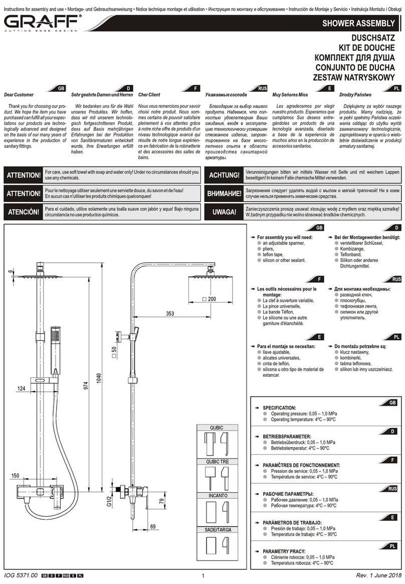
#SPECIFICATION:
Operating pressure:
Operating temperature:
#BETRIEBSPARAMETER:
Betriebsüberdruck:
Betriebstemperatur:
#PARAMČTRES DE FONCTIONNEMENT:
Pression de service:
Température de service:
#PАБОЧИЕ ПАРАМЕТРЫ:
Рабочее давление: MПа
Рабочая температура:
#PARÁMETROS DE TRABAJO:
Presión de trabajo:
Temperatura de trabajo:
#
l
l
l
l
l
l
l
l
l
l
l
l
0,05 – 1,0 MPa
4ºC – 90ºC
0,05 – 1,0 MPa
4ºC – 90ºC
0,05 – 1,0 MPa
4ºC – 90ºC
0,05 – 1,0
4ºC – 90ºC
0,05 – 1,0 MPa
4ºC – 90ºC
PARAMETRY PRACY:
Ciśnienie robocze: 0,05 – 1,0 MPa
Temperatura robocza: 4ºC – 90ºC
VIVA / PERFEQUE
TANGO
ECO
ATRIA
5
Rev 4 September 2017
