manuals.online logo
Brands
  1. Home
  2. •
  3. Brands
  4. •
  5. Graff
  6. •
  7. Bathroom Fixture
  8. •
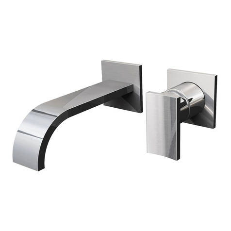
  9. Graff C14U-WS Series User manual

Graff C14U-WS Series User manual

1
ATTENTION! ATENCIÓN!
your expectations by offering you a wide range of technologically advanced
products which directly result from our many years of experience in faucet
Muchas gracias por elegir nuestro producto. Estamos seguros que podemos
atisfacer completamente sus expectativas ofreciéndole una amplia variedad
de productos tecnológicamente avanzados que resultan directamente de
muchos años de experiencia en grifos y su producción apropiada.
Dear Customer Estimado Cliente
For care, use soft towel with soap and water only! Under
no circumstances should you use any chemicals. Please be
the installation and cleaning!
Para el cuidado, utilice solamente una toalla suave con jabón
.socimíuqsotcudorpesuonaicnatsnucricanugninojaB!auqay
Hay que tener un cuidado especial para no dañar, arañar o des-
truir el acabado durante su instalación o limpieza!
IOG 2800.40 Rev. 1 July 2010
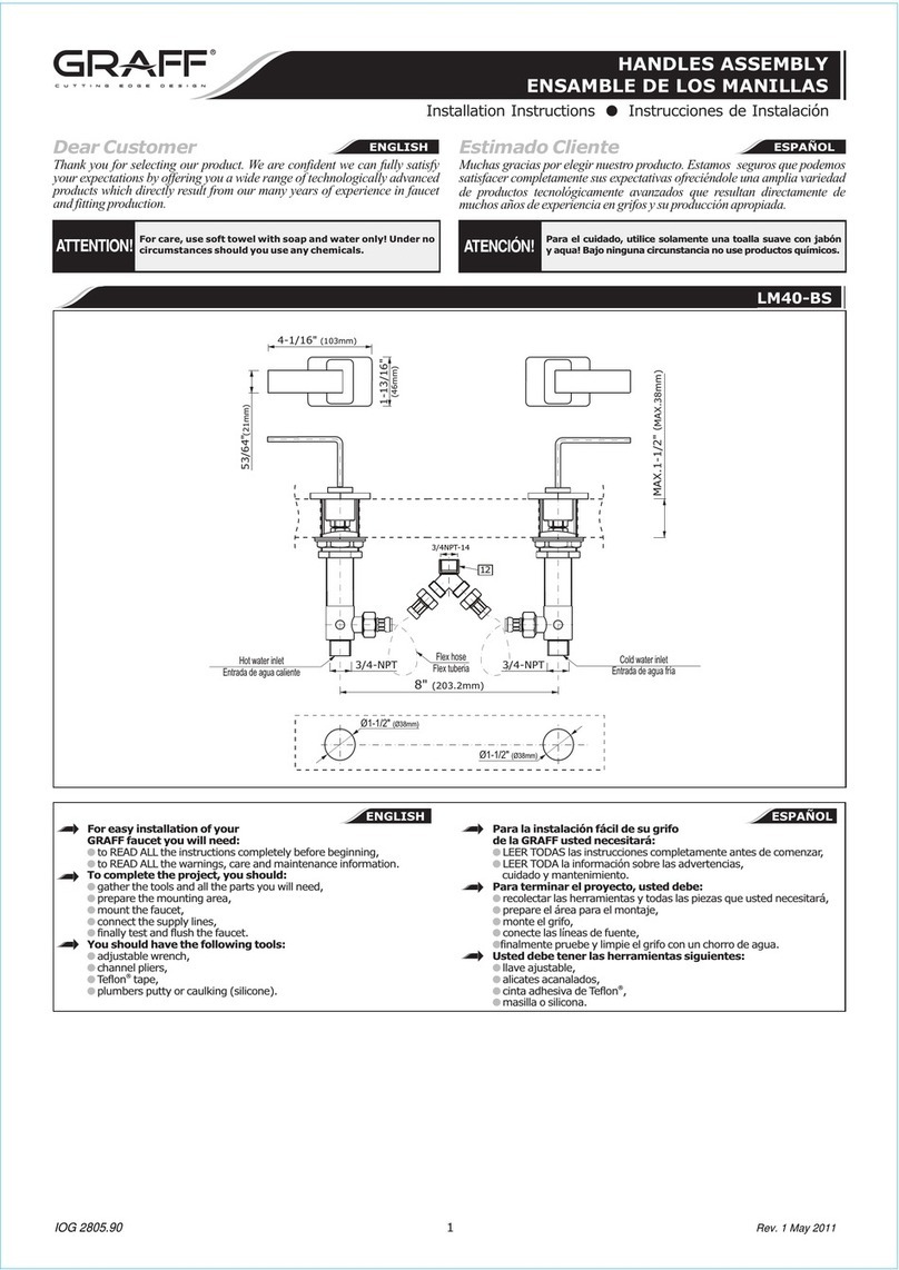
Installation Instructions ●Instrucciones de Instalación
HANDLES ASSEMBLY
ENSAMBLE DE LOS MANILLAS
C14U-WS-**
C14U-VS-**
C14U-BS-**
A-A
A
1/2 NPT
MIN. 3-1/32" (77mm)
MAX. 5-1/8" (130mm)
2-33/64" (64mm)
1-57/64" (48mm)
A
Handles assembly
Ensamble de los manillas
For easy installation of your GRAFF product you will need:
• to READ ALL the instructions completely before beginning,
•
to READ ALL the warnings, care and maintenance information.
You should have the following tools:
• Tape Measure
• Pencil
• Blade Screwdriver
• Philips Screwdriver
• Hex Wrenches
• Level
• Silicone Sealant
Para la instalación fácil de su producto de la GRAFF
usted necesitará:
LEER TODAS las instrucciones completamente antes de comenzar,
LEER TODAS la información sobre las advertencias, cuidado
y mantenimiento.
Usted debe tener las herramientas siguientes:
• Cinta para media
• Lápiz
• Destornillador plano
• Destornillador de punta de cruz o Phillips
• Llave hexagonales
• Nivel
• Sellador de silicona
ESPAÑOL
ENGLISH
1
2 3
4
5 6
89
7
K1 K2
K3
OFF OFF
ON ON
1/4 TURN
1/4 DE VUELTA
COUNTERCLOCKWISE OPENING
SE ABRE HACIA LA IZQUIERDA
1/4 TURN
1/4 DE VUELTA
COUNTERCLOCKWISE OPENING
SE ABRE HACIA LA IZQUIERDA
1-7/8" (48mm)
1-7/8" (48mm)
2-1/2" (64mm)
1-7/8" (48mm)
1-7/8" (48mm)
2-1/2" (64mm)
1
* - tipo de acabado
ATTENTION! ATENCIÓN!
2
IOG 2800.40 Rev. 1 July 2010
Installation Instructions ●Instrucciones de Instalación
HANDLES ASSEMBLY
ENSAMBLE DE LOS MANILLAS
1VALVE (with counterclockwise opening cartridge) (2 PCS.) VÁLVULA (con cartucho que se abre hacia la izquierda) (2 PIEZAS)
2STEM EXTENSION (2 PCS.) EXTENSIÓN DE ESPIGA (2 PIEZAS)
3SCREW (2 PCS.) TORNILLO (2 PIEZAS)
4PROTECTION SLEEVE (2 PCS.) CASQUILLO DE PROTECCIÓN (2 PIEZAS)
5PROTECTION CAP (2 PCS.) TAPÓN DE PROTECCIÓN (2 PIEZAS)
6HANDLE BASE (2 PCS.) BASE DE LA MANILLA (2 PIEZAS)
7HEX SET SCREW (2 PCS.) TORNILLO DEL BOQUENO (2 PIEZAS)
8SLEEVE (2 PCS.) CASQUILLO (2 PIEZAS)
9HANDLE ASSEMBLY (2 PCS.) JUEGO DE MANILLA (2 PIEZAS)
K1 7/64” (2,5mm) HEX KEY LLAVE ALLEN 7/64” (2,5mm)
K2 35/64” (14mm) SPECIAL HEX KEY LLAVE ALLEN ESPECIAL 35/64” (14mm)
K3 SPECIAL KEY (for cartridges) LLAVE ESPECIAL (para los cartuchos)
ESPAÑOLENGLISH
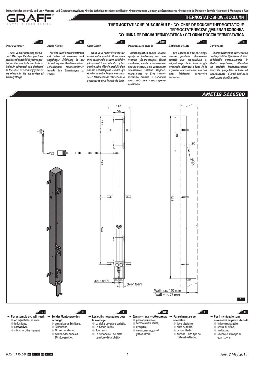
1. Prepare the recess in the wall for the valve pipe work
taking into account the maximum and minimum depth
allowed. Place valve (1) with the protection sleeve (4)
with cap (5) into the wall recess. Recommended depth
for valve in wall measured from center of valve inlet/
3-1/32”
(77mm) WALL MIN. – 5-1/8” (130mm) WALL MAX.
NOTE:
installation. Smaller diameter piping upstream or downstream
of the valve will reduce the performance of the valve.
2.
sleeve (4) together with cap (5) by turning and pulling –
3. Unscrew the screw (3), take off the stem extension (2) from
a cartridge stem. Cut the stem extension (2) at the marked-
up place using hack-saw so that the extension protrude from
after cutting. Measure the length (D) of the cut-off part of
stem extension (2), mark off from the screw end (3) the
same distance (D) and cut the screw (3) using hack-saw
4. Replace the stem extension (2) on the cartridge stem and
screw in the screw (3)
5. Turn the stem of a cartridge in a valve (1) to “OFF” position
6. Insert handle base (6) to mounting hole until snug against
(6) so that hex set screw
(7) is located at the bottom of handle base (6). The handle
7. Measure from the end of sleeve (8) the same length (D) as
in stem extension (2) and screw (3), then cut the sleeve
(8) using hack-saw at the marked-up place. Screw the
sleeve (8) into valve (1) using provided hex key (K2),
make sure that the handle base (6) is correctly located on
the wall, tighten the sleeve (8)
1. Para el trabajo de la tubería de la válvula prepare la hen-
didura en la pared, considerando la profundidad máxima y
mínima permitida. Ponga la válvula (1) junto al casquillo de
protección (4) y el tapón (5) en la hendidura de la pared.
La profundidad recomendada para el cuerpo de la válvula en
la pared medida del centro de la entrada/salida de la válvu-
3-1/32” (77mm)
WALL MIN. y 5-1/8” (130mm) WALL MAX. (ver dis. 2.1
y 2.1.1).
NB: En la instalación se recomienda usar los tubos y accesorios
de cobre del tamaño nominal de 1/2”. Un diámetro más peque-
ño de los tubos de entrada y salida de la válvula puede causar
Averigue si en la válvula no hay fugas. Termine el acabado de
la pared.
2. Al terminar el acabado de la pared quite el casquillo de pro-
tección (4) y el tapón (5) girando y tirandólos - ver dis. 2.2.
3. Destornille el tornillo (3), quite la extensión de la espiga (2)
del cartucho. Corte la extensión de espiga (2) en el lugar
marcado con un serrucho para metal de tal modo que la ex-
tremidad emerja de la cara interior de la pared de acabado
de unos 0.2” (5mm); elimine todas las rebabas que se pue-
dan producir en el momento de cortar. Mida la extremidad
cortada (D) de la extensión de la espiga (2), mida la misma
distancia (D) (3) y corte el
tornillo (3) en el lugar marcado con un serrucho para metal
(ver dis. 2.3 y 2.3.1).
4. Inserte de nuevo la extensión de espiga (2) en el cartucho
y apriete el tornillo (3) - ver dis. 2.4.
5. Ponga la espiga del cartucho en la válvula (1) en la posición
“cartucho cerrado” - “OFF” (a la derecha) - ver dis. 2.5.
6. Coloque la base de la manilla (6) en el agujero de montaje
hasta que toque la pared de acabado. Coloque la base de
la manilla (6) de tal modo que el tornillo haxagonal (7) se
encuentre en la parte baja de la base de la manilla (6). La
base de la manilla debe instalarse tal como se indica en el
dis. 2.5.
7. (8) la misma distancia (D)
que en caso de la extensión de espiga (2) y tornillo (3),
luego corte el casquillo (8) en el lugar marcado con un se-
rrucho para metal. Enrosque el casquillo (8) en la válvula
(1) con una llave allen (K2) adjuntata prestando atención a
la posición correcta de la base de la manilla (6) en la pared,
apriete el casquillo (8) - ver dis. 2.6.
ESPAÑOLENGLISH
VALVE & HANDLE INSTALLATION •INSTALACIÓN DE LA VÁLVULA Y LA MANILLA
ATTENTION! ATENCIÓN!
3
IOG 2800.40 Rev. 1 July 2010
Installation Instructions ●Instrucciones de Instalación
HANDLES ASSEMBLY
ENSAMBLE DE LOS MANILLAS
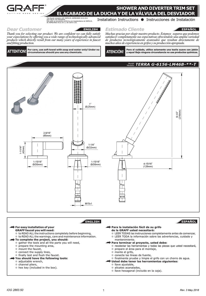
8. Put the hex key (K1) into the hole of the slide ring (S) in
handle (9) and rotate the ring (S) so that the hole in the
ring is in bottom position facing the hex set screw (7) in the
handle base (6) (K1)
from the hole and push in the handle assembly (9) onto
stem extension (2) (9) as on
9. Block carefully the handle (9) with a set screw (7) using the
screw
pin should enter the hole in the slide ring (S). In case
handle loosen up the set screw (7) by a 1⁄4 turn.
Repeat steps for second valve and handle.
8. Ponga la llave hexagonal (K1) en el agujerito del anillo de
deslizamiento (S) en la manilla (9) y gire todo el anillo (S)
hasta el punto donde el agujerito del anillo se encuentre al
frente del tornillo hexagonal (7) en la base de la manilla
(6) - ver dis. 2.7. Quite la llave hexagonal del agujerito y
ponga el juego de manilla (9) en la extensión de espiga (2)
- ver dis. 2.7. Ponga la manilla (9) como en el dis. 1 en la
posición “OFF”.
9. Bloquee con cuidado la manilla (9) con el tornillo (7) usan-
do la llave hexagonal (que va junto con el grifo) - ver dis.
2.8. El gorrón del tornillo tiene que entrar en agujerito del
anillo de deslizamiento (S) de la manilla. En el caso de una
-
(7) a 1⁄4 de su rotación.
Repita los pasos descritos para otra válvula y manilla.
ESPAÑOLENGLISH
VALVE & HANDLE INSTALLATION •INSTALACIÓN DE LA VÁLVULA Y LA MANILLA
2.3.1
1
4 5
1
4 5
2.22.1
2 3
2.3
2.1.1
1
2
3
1
6
7
2.4 2.5 2.6
ATTENTION! ATENCIÓN!
4
IOG 2800.40 Rev. 1 July 2010
Installation Instructions ●Instrucciones de Instalación
HANDLES ASSEMBLY
ENSAMBLE DE LOS MANILLAS
S
K1 9
1
2
9
6
7
K1
2.7 2.8
by turning the handle in counterclockwise direction. The
0° ÷ 90° angle.
Para abrir la salida de ajuste de temperatura use la manilla.
La apertura completa/maxima obtiene girando la manilla a la
sucede en las posiciones entre 0° ÷ 90°.
ESPAÑOLENGLISH
OPERATING INSTRUCTIONS •DESCRIPCIÓN DEL FUNCIONAMIENTO
Your Graff product is designed and engineered in accordance
with the highest quality and performance standards.Be sure
extremely durable, it can be damaged by harsh abrasives or
polish. Never use abrasive cleaners, acids, solvents, etc. to
clean any Graff product. To clean, simply wipe gently with
a damp cloth and blot dry with a soft towel.
Warranty conditions and warranty registration card are outlined
on a separate sheet.
Su producto de la Graff esta diseñado y dirigido acuerdo con los
estándares de funcionamiento y calidad más altos. Este seguro
no dañar las terminaciones del grifo durante la instalación. Cu-
ide el producto manteniendolo siempre limpio. Aunque su aca-
bado es extremadamente durable, puede ser dañado por los
abrasivos o pulientes ásperos. Nunca utilice limpiadores abrasi-
vos, ácidos, solventes, el etc. para limpiar cualquier producto de
la Graff. Para limpiar, simplemente use un paño húmedo y seque
con una toalla suave.
Las condiciones de la garantía y la tarjeta del registro de la ga-
rantía se encuentran en una pagina separada.
ESPAÑOLENGLISH
CARE AND MAINTENANCE / WARRANTY •CUIDADO Y MANTENIMIENTO / GARANTÍA
All dimensions and drawings are for reference only. For details, please refer to actual products.
Todas las dimensiones y dibujos sirven únicamente de referencia. Para consultar detalles, ver los productos.
www.graff-designs.com

This manual suits for next models

2

Other Graff Bathroom Fixture manuals

Graff E-7057 Operator's manual

Graff

Graff E-7057 Operator's manual

Graff 8618 User manual

Graff

Graff 8618 User manual

Graff FIN92 User manual

Graff

Graff FIN92 User manual

Graff SENTO-6355-T User manual

Graff

Graff SENTO-6355-T User manual

Graff EX-11170 Operator's manual

Graff

Graff EX-11170 Operator's manual

Graff Ametis G-6430-LM43PC User manual

Graff

Graff Ametis G-6430-LM43PC User manual

Graff E-11900-LM69 Operator's manual

Graff

Graff E-11900-LM69 Operator's manual

Graff Ametis G8750WTBK User manual

Graff

Graff Ametis G8750WTBK User manual

Graff M.E.25 6156-LM41B-T User manual

Graff

Graff M.E.25 6156-LM41B-T User manual

Graff G-8231 User manual

Graff

Graff G-8231 User manual

Graff EX-1872-LM31W Operator's manual

Graff

Graff EX-1872-LM31W Operator's manual

Graff TEP92 User manual

Graff

Graff TEP92 User manual

Graff E-11557 L1 Series Operator's manual

Graff

Graff E-11557 L1 Series Operator's manual

Graff G-8220 User manual

Graff

Graff G-8220 User manual

Graff Vignola E-7045-LM60N Operator's manual

Graff

Graff Vignola E-7045-LM60N Operator's manual

Graff E-9901 Operator's manual

Graff

Graff E-9901 Operator's manual

Graff SOLAR Operator's manual

Graff

Graff SOLAR Operator's manual

Graff Harley E-8714-HS2 Operator's manual

Graff

Graff Harley E-8714-HS2 Operator's manual

Graff AMETIS G User manual

Graff

Graff AMETIS G User manual

Graff ME E-6140 Series Operator's manual

Graff

Graff ME E-6140 Series Operator's manual

Graff Incanto E-11202 Series User manual

Graff

Graff Incanto E-11202 Series User manual

Graff ONDA E-6354-LM61N Series Operator's manual

Graff

Graff ONDA E-6354-LM61N Series Operator's manual

Graff ONDA E-6315-LM61N-T Operator's manual

Graff

Graff ONDA E-6315-LM61N-T Operator's manual

Graff E-6910-C16B-PC Operator's manual

Graff

Graff E-6910-C16B-PC Operator's manual

Popular Bathroom Fixture manuals by other brands

Luxier SP20-SS manual

Luxier

Luxier SP20-SS manual

Jula 434-036 installation instructions

Jula

Jula 434-036 installation instructions

Fleurco LA06 installation manual

Fleurco

Fleurco LA06 installation manual

Sanipex BAGNODESIGN BRISTOL BDM-BIS-315 Series installation guide

Sanipex

Sanipex BAGNODESIGN BRISTOL BDM-BIS-315 Series installation guide

Blaufoss ORION installation guide

Blaufoss

Blaufoss ORION installation guide

Agua VITO II Installation

Agua

Agua VITO II Installation

poolstar formidra DADA Curve installation guide

poolstar

poolstar formidra DADA Curve installation guide

Axor One 45711 1 Series Installation/User Instructions/Warranty

Axor

Axor One 45711 1 Series Installation/User Instructions/Warranty

Triton Jade 3 Installation and operating instructions

Triton

Triton Jade 3 Installation and operating instructions

MAAX 102886 installation instructions

MAAX

MAAX 102886 installation instructions

Mirabelle St. Martin MIRSM4RTGCP quick start guide

Mirabelle

Mirabelle St. Martin MIRSM4RTGCP quick start guide

Grohe Geneva 20 801 quick start guide

Grohe

Grohe Geneva 20 801 quick start guide

Luxart smart surround LXSS1010 manual

Luxart

Luxart smart surround LXSS1010 manual

Gessi ANELLO 63469 Bath Mixing Program

Gessi

Gessi ANELLO 63469 Bath Mixing Program

Spectrum Brands Pfister Saxton LG89-XGL1 Maintenance & Care Guide

Spectrum Brands

Spectrum Brands Pfister Saxton LG89-XGL1 Maintenance & Care Guide

PHARO Steuerung Poolmaster V1 Service

PHARO

PHARO Steuerung Poolmaster V1 Service

Mirabelle MIRBE9005CP quick start guide

Mirabelle

Mirabelle MIRBE9005CP quick start guide

ERLIT ER 10109V user manual

ERLIT

ERLIT ER 10109V user manual

manuals.online logo
manuals.online logoBrands
  • About & Mission
  • Contact us
  • Privacy Policy
  • Terms and Conditions

Copyright 2025 Manuals.Online. All Rights Reserved.