manuals.online logo
Brands
  1. Home
  2. •
  3. Brands
  4. •
  5. Graff
  6. •
  7. Bathroom Fixture
  8. •
  9. Graff EX-1872-LM31W Operator's manual

Graff EX-1872-LM31W Operator's manual

QUBIC TRE
QUBIC
Rev. 1 June 2018
353
200q
1040
974
69
G1/2
124
6
50q
79
150
INCANTO
SADE/TARGA
IOG 5371.00
Rev. 1 June 2018IOG 5371.00
2
1
2
3
4
5
6
7
8
9
10
10
11
11
12
13
14
15
16
17
19
21
22
24
25
18
20
23
26
27
28
29
30
31
A
B
30
29
13
Rev. 1 June 2018IOG 5371.00
3
Shower body assembly
(complete)
Shower body
Mixer Ø40mm
Mixer nut
Decorative cap
Lever
Screw
Connector
Hole plug
O-ring
Nut G3/4
Flat washer
Dog-leg connector
G3/4-G1/2
Screw
Rosette ring
Shower arm - lower assembly
Shower arm - lower
Switch
Connector G1/2 for shower hose
Screw
Shower arm - upper assembly
Shower arm - upper
O-ring
Connector G1/2 for shower
head
Support for arm
Screw
Connector
Rosette for support unit
Screw
Screw
Slide mechanism
Wall plug
Flat washer
Shower head
2 mm hexagon key
2.5 mm hexagon key
1A
1
2
3
4
5
6
7
8
9
10
11
12
13
14
15A
15
16
17
18
19A
19
20
21
22
23
24
25
26
27
28
29
30
31
A
B
Duschkörper kpl. (komplett)
Duschkörper
Wassermischer Ø40mm
Mutter Wassermischer
Zierkappe
Hebel
Schraube
Verbinder
Blindplatte
O-Ring-Dichtung
Mutter G3/4
Flachdichtung
Exzenterverbinder
G3/4-G1/2
Schraube
Rosette
Duscharm - unten kpl.
Duscharm - unten
Umschalter
Anschluss des Duschschlauches G1/2
Schraube
Duscharm - oben kpl.
Duscharm - oben
O-Ring-Dichtung
Anschluss der Überkopfbrause
G1/2
Armbefestigung
Schraube
Verbinder
Griffrosette
Schraube
Schraube
Duschstangen-mechanismus
Spreizdübe
Flachdichtung
Überkopfbrause
Innensechskantschlüssel 2 mm
Innensechskantschlüssel 2,5 mm
Colonne de douche (kit complet)
Colonne de douche
Mitigeur Ø40mm
Écrou du mitigeur
Capuchon décoratif
Levier
Vis
Raccord
Obturateur
Joint de type o-ring
Écrou G3/4
Joint plat
Raccord excentré
G3/4-G1/2
Vis
Rosace
Bras de douche
(partie basse- complčte)
Bras de douche (bas)
Commutateur
Commutateur G1/2 du tuyau de douche
Vis
Bras de douche
(partie haut e compl čte)
Bras de douche haut
Joint de type o-ring
Raccord G1/2 du pommeau de
douche
Fixation du bras de douche
Vis
Raccord
Rosace du point de fixation
Vis
Vis
Mécanisme de douche coulissante
Cheville expansible
Joint plat
Tęte de douche
Clef Allen 2 mm
Clef Allen 2,5 mm
Koрпус душа компл. (комплект)
Корпус душевого крана
Смеситель Ø40мм
Гайка смесителя
Декоративный колпачок
Рукоятка крана
Болт
Соединитель
Заглушка
Уплотнение типа o-ring
Гайка G3/4
Плоская прокладка
Эксцентриковый соединитель
G3/4-G1/2
Болт
Декоративный элемент
Кронштейн душа - нижний
компл.
Кронштейн душа - нижний
Переключатель
Присоединение G1/2 шланга душа
Болт
Кронштейн душа - верхний
компл.
Кронштейн душа - верхний
Уплотнение типа o-ring
Присоединение G1/2 головки
душа
Крепление кронштейна
Болт
Соединитель
Декоративный элемент держателя
Болт
Болт
Механизм душевой колонны
Распорный колышек
Плоская прокладка
Душевая головка
Шестигранный ключ 2мм
Шестигранный ключ 2,5мм
Cuerpo ducha juego (completo)
Cuerpo ducha
Mezclador Ø40mm
Tuerca mezclador
Caperuza ornamento
Palanca
Trnillo
Pieza de unión
Obturador
Junta tórica
Tuerca G3/4
Junta plana
Pieza de unión excéntrica
G3/4-G1/2
Tornillo
Roseta
Brazo ducha - inferior juego
Brazo ducha - inferior
Conmutador
Racor G1/2 manguito ducha
Tornillo
Brazo ducha superior juego
Brazo ducha superior
Junta tórica
Racor G1/2 cabezal ducha
Sujeción brazo
Tornillo
Pieza de unión
Roseta mango
Tornillo
Tornillo
Mecanismo barra deslizante
Pasado
Junta plana
Cabezal ducha
La llave allén 2 mm
La llave allén 2,5 mm
Korpus natrysku (kompletny)
Korpus natrysku
Mieszacz Ø40mm
Nakrętka mieszacza
Kołpak ozdobny
Dźwignia
Wkręt M4x4 z gniazdem 6kt
Łącznik
Zaślepka
Uszczelka typu o-ring
Nakrętka G3/4
Uszczelka płaska
Łącznik mimośrodowy
G3/4-G1/2
Wkręt
Rozeta
Ramię natrysku - dolne kpl.
Ramię natrysku - dolne
Przełącznik
Przyłącze G1/2 węża natrysku
Wkręt
Ramię natrysku - górne kpl.
Ramię natrysku - górne
Uszczelka typu o-ring
Przyłącze G1/2 głowicy
natrysku
Mocowanie ramienia
Wkręt
Łącznik
Rozeta uchwytu
Wkręt
Wkręt
Suwak słuchawki prysznicowej
Kołek rozporowy
Uszczelka płaska
Głowica natryskowa
Kluczyk imbusowy 2 mm
Kluczyk imbusowy 2,5 mm
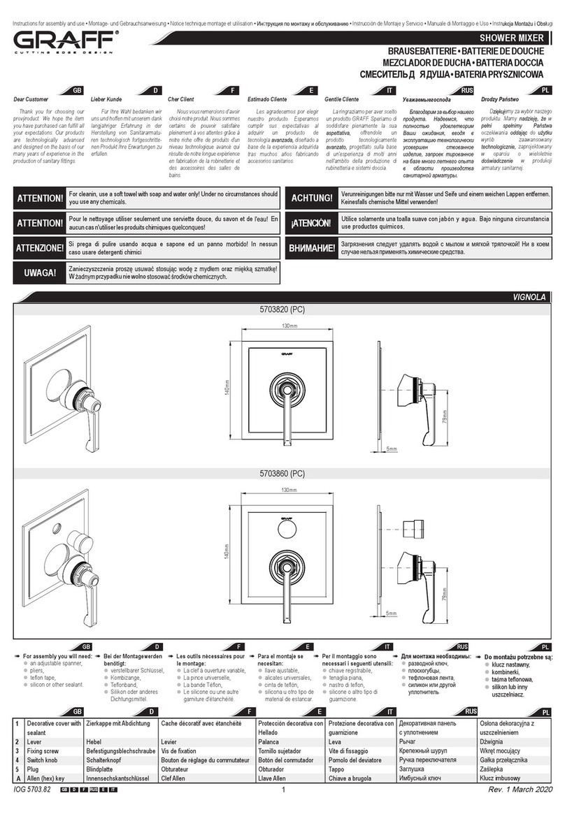
SHOWER BODY ASSEMBLY
See fig. 2.1-2.4
The hot and cold water supply system should be installed and the mixer tap connected observing the following recommendations:
The hot water coupling should be located on the right and the cold water coupling should be located on the left,
Coupling spacing: 150 ± 14 mm,
Recommended installation height for the mixer tap: 900-1000mm from the finished floor .
Fit the dog-leg connectors (12) to the pipe sections where they exit the wall, first sealing them with teflon tape or other sealant, making sure that the dog-leg connector outlets are set at equal height with the
end faces at equal distances from the wall and that the distance between openings matches the distance between those of the connecting nuts (10) of the shower body (1A).
Screw the rosette rings (14) onto the dog-leg connectors (12) until a visible resistance is felt.
Insert the gaskets (11) into the connecting nuts (10) and screw them onto the dog-leg connectors (12). Check the tightness of the connection after assembly.
MONTAGE DES DUSCHKÖRPERS
Siehe Zeichnung 2.1-2.4
Installieren Sie die Warm- und Kaltwasseranlage an der für die Batteriemontage vorgesehenen Stelle gemäß den unten genannten Hinweisen
der Warmwasseranschluss ist links und der Kaltwasseranschluss rechts anzubringen,
der Abstand der Anschlüsse sollte im Bereich: 150±14mm liegen,
die empfohlene Höhe der Batteriemontage sollte 900-1000mm vom Fußbodenausbau betragen.
In die mit dem Innengewinde G1/2” abgeschlossenen Strecken sind die Exzenterverbinder (12) einzudrehen und die Verbindungen mit dem PTFE-Band (oder mit einem anderen Dichtmittel) abzudichten zu
beachten ist, dass die Öffnungsachsen der Exzenter (12) von der Gewindeseite G3/4” auf derselben Höhe liegen, die Stirnflächen im gleichem Abstand von der Wand liegen, und der Öffnungsabstand dem
Abstand der Achsen der Anschlussmutter (10) des Duschkörpers (1A) entspricht.
Auf die Exzenterverbinder (12) die Rosetten (14) bis zum spürbaren Widerstand aufschrauben.
In die Anschlussmuttern (10) Dichtungen (10) einlegen und sie auf die Exzenterverbinder aufschrauben, nach der Montage die Verbindungen auf Dichtigkeit prüfen.
GB
D
Rev. 1 June 2018IOG 5371.00
4
2
Assembly dimensions • Einbaumasse • Côtes de montage • Монtaжная выcota
Dimensiones de montaje • Wymiary montażowe
1,65 m- 1,75 m
M~2,12 m
>P> M~2,02 m
1,65 m
≥PM~1,92 m
P≥M
185 m ~2,22 m
>P> 1,75 m- 1,85 m
1,65 m- 1,75 m
H~1,15 m
>P> H~1,05 m
1,65 m
≥PH~0,95 m
P≥H
185 m ~1,25 m
>P> 1,75 m- 1,85 m
P
M
H~702mm
MONTAGE DE LA COLONNE DE DOUCHE
Voire la figure 2.1-2.4
Installez les arrivées d'eau chaude et d'eau froide à l'emplacement où vous souhaitez installez les robinets, en respectant les consignes suivantes:
la sortie d'eau chaude doit se trouver du côté gauche, celle d'eau froide du côté droit,
la distance entre les deux sorties doit être comprise entre: 150±14mm,
il est conseillé de monter les robinets à une hauteur de: 900-1000mm à partir du sol posé.
Vissez les raccords excentrés (12) dans les segments de l'installation terminés par un filetage intérieur G1/2”, en garnissant les raccords de bande en téflon (ou d'un autre produit assurant
l'étanchéité) vérifiez que les axes des orifices des raccords excentrés (12) situés du côté du filetage G3/4” se trouvent à hauteur identique, que les surfaces frontales sont à distance égale du
mur et que la distance entre les orifices est égale à la distance entre les axes des écrous de raccordement (10) de la colonne
de douche (1A).
Visser les raccords excentrés (12) sur les manchons décoratifs (14) jusqu'à ce que vous sentiez une nette résistance.
Placez les joints (11) à l'intérieur des écrous de raccordement (10) et vissez-les sur les raccords excentrés (12); après avoir effectué ce montage, vérifiez l'étanchéité des raccordements.
F
Rev. 1 June 2018IOG 5371.00
5
MOНТАЖ КОРПУСА ДУШЕВОГО КРАНА
См. рис. 2.1-2.4
Подвести шланги для горячей и холодной воды к месту монтажа смесителя в соответствии с указаниями:
подсоединение горячей воды должно быть с левой стороны, подсоединение холодной воды с правой стороны,
расстояние между подсоединениями должно составлять не более 150±14мм,
рекомендуется устанавливать смеситель на высоте 900-1000мм oт окончательного уровня пола.
На концы с внутренней резьбой G1/2”, ввинтите эксцентриковые соединители (12), уплотняя соединение тефлоновой лентой (или другим уплотняющим материалом) обращайте внимание
на то, чтобы оси отверстий эксцентриков (12) со стороны резьбы G3/4” располагались на одной высоте, торцевые поверхности на одинаковом расстоянии от стены, а расстояние между
отверстиями равнялось расстоянию между осями гаек (10) в корпусе смесителя (1A).
Навинтите декоративный элемент (14) на эксцентриковые соединители (12) до упора.
Вложите в гайки (10) уплотнительные прокладки (11) и навинтите их на эксцентриковые соединители (12), по окончании проверьте герметичность соединений.
RUS
INST ALACIÓN DEL CUERPO DE DUCHA
Ver fig. 2.1-2.4
Conecte la instalación del agua caliente y fría al lugar de instalar la batería siguiendo las recomendaciones:
la acometida del agua caliente por el lado izquierdo, la acometida de la fría, por el derecho,
la distancia ente las acometidas debe caber dentro de los límites: 150±14mm,
la altura recomendada de la instalación de la batería: 900-1000mm sobre el nivel del suelo.
En las secciones de la instalación acabadas con rosca interna G1/2” enrosque las piezas de unión excéntricas (12), aislando las uniones con la cinta de teflón (u otro tipo de guarniciones) haga
caso que los ejes excéntricos (12) por el lado de la rosca G3/4” se encuentren en la misma altura, las superficies frontales tengan la misma distancia de la pared, y el espacio entre los huecos
sea igual que la distancia entre los ejes de las tuercas (10) del cuerpo ducha (1A).
En las piezas de unión excéntricas (12) meta las rosetas (14) hasta el momento de sentir la resistencia.
Meta dentro de las tuercas (10) las juntas (11) y enrósquelas en las piezas de unión excéntricas (12), tras instalar compruebe la estanquidad de las uniones.
E
MONTAŻ KORPUSU NATRYSKU
Zob. rys. 2.1-2.4
Doprowadź instalację ciepłej i zimnej wody w miejsce montażu baterii zgodnie z zaleceniami:
przyłącze wody ciepłej wykonaj po stronie lewej, przyłącze wody zimnej po prawej,
rozstaw przyłączy musi się mieścić w zakresie: 150±14 mm,
zalecana wysokość montażu baterii: 900-1000mm od wykończonej podłogi.
Do odcinków instalacji zakończonych gwintem wewnętrznym G1/2” wkręć łączniki mimośrodowe (12), uszczelniając połączenia taśmą teflonową (lub innymi uszczelniaczami) - zwrócić uwagę na to,
aby osie otworów mimośrodów (12) od strony gwintu G3/4” były na jednej wysokości, powierzchnie czołowe w jednakowej odległości od ściany, a odstęp otworów był równy odległości osi nakrętek przyłącze-
niowych (10) korpusu natrysku (1A).
Na łączniki mimośrodowe (12) nakręć rozety (14) do momentu odczucia wyraźnego oporu.
Włóż do nakrętek przyłączeniowych (10) uszczelki (11) i nakręcić je na łączniki mimośrodowe (12), po zmontowaniu sprawdź szczelność połączeń.
PL
Rev. 1 June 2018IOG 5371.00
6
LOWER AND UPPER ARM ASSEMBLY AND THE SHOWER HEAD
See fig. 3.1-3.6
Insert the connector pipes with the o-rings of the upper arm of the shower (19) into the lower pipe of
the shower (15). Set the parts (19) and (15) in the correct position and fit the screws (18) using a
hexagon key. Set the fixing element (22) in the correct position.
Slide the assembly holder (23) onto the connector (24). Slide the lower end of the arm of the shower
(15) onto the connector pipe with the o-ring (7) of the shower body (1A).
Set the installation holder (23) correctly on the wall (see fig.3.4) and mark the point for installing the
wall plug. Slide out the complete shower arm from the connector pipe (7) of the shower body and
place it on the side, slide the installation holder (23) from the connector (24).
Drill Ø6mm holes (see fig.3.4), insert wall plug (29) to the holes and attach the rosette (25) to the
wall (27).
Screw the assembly holder (23) on the rosette (25). Slide the lower end of the arm of the shower (15)
onto the connector pipe with o-ring (7) of the shower body (1A) and slide the connector (24) into the
installation holder (23) Set the complete shower arm in the correct position and screw in the screws
(18) using a hexagon key.
Screw the shower head nut (31) onto the connector (21) in the upper shower (19). Pay attention to
the correct position of the flat gasket (30) in the shower head nut (31).
D
3.1 3.2 3.3
18
19
22
23
23
Ø18mm
Ø6mm
Den Stutzen mit den O-Ringen des oberen Duscharmes (19) in den unteren Duscharm (15)
einschieben. Die Teile (19) und (15) in richtiger Stellung (18) positionieren und mit dem Innensech-
skantschlüssel festziehen. Das Befestigungselement (22) in richtiger Lage positionieren.
Auf den Verbinder (24) den Montagehalter (23) aufschieben. Die untere Endung des Duscharmes
(15) auf den Stutzen mit dem O-Ring (7) des Duschkörpers (1A) aufschieben.
Den Montagehalter (23) in richtiger Stellung an der Wand (gemäß Abb. 3.4) positionieren und
Punkte für die Montagedübel markieren. Aus dem Stutzen (7) des Duschkörpers den kompletten
Duscharm aufschieben und zur Seite ablegen, aus dem Verbinder (24) den Montagehalter (23)
herausschieben.
Bohren Sie Öffnungen Ø6mm (gemäß Abb. 3.4), legen Sie die Spreizdübel (29) in die Öffnungen
und befestigen Sie den Rosette (25) mittels Schrauben (30) an der Wand.
Anschrauben die Montageöffnung (23) auf die Rosette (25). Die untere Endung des Duscharmes
(15) auf den Stutzen mit dem O-Ring (7) des Duschkörpers (1A) aufschieben, den Verbinder (24) in
die Montageöffnung (23) einschieben. Den kompletten Duscharm in richtiger Stellung positionieren,
anschließend die Schrauben (18) mit dem Innensechskantschlüssel zudrehen.
Auf den Anschluss (21) im oberen Duscharm (19) die Mutter der Überkopfbrause (31) aufdrehen.
Beachten Sie die richtige Lage der Flachdichtung (30) in der Kopfmutter (31).
MONTAGE DES UNTEREN UND OBEREN ARMES UND DER ÜBERKOPFBRAUSE
Siehe Zeichnung 3.1-3.6
GB
Rev. 1 June 2018IOG 5371.00
7
3.4 3.5 3.6
29 25
27 23 26
23
2425
13
13
30
21
RUS
MONTAGE DU BRAS SUPÉRIEUR, INFÉRIEUR ET DE LA TĘTE DE LA DOUCHE
Voire la figure 3.1-3.6
Introduisez le manchon avec les o-rings du bras supérieur de la douche (19) dans le bras inférieur
de la douche (15). Placez les pièces (19) et (15) dans la bonne position et serrez les vis (18) à l'aide
d'une clef Allen. Placez la fixation du bras de douche dans la bonne position (22).
Enfilez le point de montage (23) sur le raccord (24). Enfilez l'extrémité basse du bras de la douche
(15) sur le manchon équipé d'un o-ring (7) de la colonne de douche (1A).
Placez la fixation du bras de douche au bon endroit sur le mur (23) (conformément au dessin 3.4) et
faite marques, indiquant les point où doivent se trouver les chevilles de montage. Sortez le bras de
douche complet du manchon (7) de la colonne de douche et mettez-le de côté, sortez la fixation du
bras de douche (23) en la faisant glisser du raccord (24).
Percer trous de Ø6 mm (conformément au dessin 3.4), mettez dedans les chevilles expansibles
(29) et installez la fixation de rosace (25) sur le mur à l'aide des vis (27).
Placez la rosace (25) avec le point de montage (23). Enfilez l'extrémité du bras de la douche (15)
sur le manchon équipé du o-ring (7) de la colonne de douche (1A), placez le raccord (24) dans la
fixation du bras de douche (23). Placez le bras de la douche complet dans la bonne position, puis
serrez les vis (18) à l'aide d'une clef Allen.
Vissez l'écrou de la tête de douche (31) sur le raccord (21) du bras supérieur de la douche (19) puis
vissez l'écrou de la tête de douche. Assurez-vous du bon positionnement du joint plat (30) dans
l'écrou de la tête de douche (31).
Вставьте патрубок верхнего кронштейна душа (19) с уплотнениями o-ring в нижний кронштейн
душа (15). Отрегулируйте установку элементов (19) и (15) в нужном положении и затяните
болты (18) с помощью шестигранного ключа. Установите в нужном положении крепежный
элемент (22).
На соединитель (24) наденьте монтажный держатель (23). Нижний конец кронштейна душа
(15) наденьте на патрубок с уплотнением o-ring (7) на корпусе душевого крана (1A).
Установите в нужном положении на стене монтажный держатель (23) (в соотв. с рис. 3.4) и
разметьте пункта под монтажные колышки. Извлеките из патрубка (7) корпуса душа
кронштейн душа и отложите сбоку, снимите с соединителя (24) монтажный держатель (23).
Высверлите oтверстия 6мм (в соотв. с рис. 3.4), вставьте в отверстия распорные колышки
(29), с декоративный элемент держателя (27) прикрепите монтажный держатель (30) к стене.
Привинтить соединитель (24) на декоративный элемент (25). Нижний конец кронштейна
душа (15) наденьте на патрубок с уплотнением o-ring (7) на корпусе душевого крана (1A),
соединитель (24) вставьте в монтажный держатель (23). Отрегулируйте установку
комплектного кронштейна душа в нужном положении, а затем затяните болты (18) с
помощью шестигранного ключа.
На подсоединение (21) в верхнем кронштейне душа (19) навинтите гайку душевой головки
(31). Обращйте внимание на правильное положение плоской уплотнительной прокладки (30)
в гайке головки (31)
MOНТАЖ НИЖНЕГО И ВЕРХНЕГО КРОНШТЕЙНА И ДУШЕВОЙ ГОЛОВКИ
См. рис. 3.1-3.6
F
Rev. 1 June 2018IOG 5371.00
8
INST ALACIÓN DE LOS BRAZOS INFERIOR, SUPERIOR Y EL CABEZAL DE DUCHA
Ver fig. 3.1-3.6
Meta el racor con las juntas tóricas del brazo superior de ducha (19) en el brazo interior de ducha
(15). Coloque las piezas (19) y (15) en la posición adecuada y enrosque los tornillos (18) usando la
llave allén. Coloque en la posición adecuada el elemento de sujeción (22).
En la pieza de unión (24) meta el mango de instalación (23). El extremo inferior del brazo de ducha
(15) meta en el racor con la junta tórica (7) del cuerpo ducha (1A).
Coloque el mango de instalación (23) en la posición adecuada en la pared (ver la fig. 3.4) y marque
puntos para pasadores. Quite del racor (7) del cuerpo de ducha el brazo completo y póngalo a lado,
quite de la pieza de unión (24) el mango de instalación (23).
Taladrar agujeros Ø6mm (ver la fig. 3.4), meta dentro los pasadores (29), sujete el roseta (25) en la
pared usando los tornillos (27).
Enroscar la roseta (25) a mango de instalación (23). El extremo inferior del brazo de ducha (15)
meta en el racor con la junta tórica (7) del cuerpo de ducha (1A), meta la pieza de unión (24) en
el mango de instalación (23). Coloque el brazo completo de ducha en la posición adecuada, luego
enrosque los tornillos (18) usando la llave allén.
En el racor (21) en el brazo superior de la ducha (19) enrosque la tuerca del cabezal de ducha (31).
Fíjese en la posición adecuada de la junta plana (30) en la tuerca del cabezal 31).
PL
MONTAŻ RAMIENIA DOLNEGO, GÓRNEGO I GŁOWICY NATRYSKU
Zob. rys. 3.1-3.6
Wsuń króciec z o-ringami górnego ramienia natrysku (19) do dolnego ramienia natrysku (15). Ustaw
części (19) i (15) we właściwej pozycji i dokręć wkręty (18) kluczykiem imbusowym. Ustaw we
właściwej pozycji element mocujący (22).
Na łącznik (24) nasuń uchwyt montażowy (23). Dolną końcówkę ramienia natrysku (15) nasuń na
króciec z o-ringiem (7) korpusu natrysku (1A).
Ustaw we właściwej pozycji na ścianie uchwyt montażowy (23) (zgodnie z rys. 3.4) i odznacz punkt
pod kołek montażowy. Wysuń z króćca (7) korpusu natrysku kompletne ramię natrysku i odłóż je na
bok, zsuń z łącznika (24) uchwyt montażowy (23).
Wywierć otwór Ø6mm (zgodnie z rys. 3.4), włóż kołki rozporowe (29) do otworów, przymocuj rozetę
uchwytu (25) do ściany wkrętem (27).
Łącznik (23) nakręć na rozetę (25). Dolną końcówkę ramienia natrysku (15) nasuń na króciec z
o-ringiem (7) korpusu natrysku (1A), łącznik (24) wsuń w uchwyt montażowy (23). Ustaw kompletne
ramię natrysku we właściwej pozycji, następnie dokręć wkręty (18) kluczem imbusowym.
Na przyłącze (21) w górnym ramieniu natrysku (19) nakręć nakrętkę głowicy natryskowej (31).
Zwróć uwagę na poprawne ułożenie uszczelki płaskiej (30) w nakrętce głowicy (31).
E
30
29
17
4
28
SHOWER SET
See fig.4
GB
Screw the shower hose nut (29) onto the connector (17). Screw the second conic shower hose nut onto the handset connector
pipe (30). Remember to fit the flat gaskets inside the both nuts of shower hose.
Place the handset (30) inside the holder (28).
MONTAGE DES DUSCHSATZES
Siehe Zeichnung 4
D
Die Mutter des Duschschlauches (29) auf den Anschluss (17). Die zweite Kegelmutter des Duschschlauches auf den Stutzen
des Handduschkopfes (30) aufdrehen. Vergessen Sie nicht, die Flachdichtungen in beide Muttern des Duschschlauchs
einzusetzen.
Den Duschkopf (30) im Halter (28) anbringen.
MONTAGE DU KIT DE DOUCHE
Voire la figure 4
F
Vissez l'écrou du tuyau de douche (29) sur le raccord (17). Visser le second écrou conique du tuyau de la douche sur le
manchon du pommeau de douche (téléphone) (30). N'oubliez de placer des joints plats ŕ l'intérieur des deux écrous du tuyau de
douche.
Placez le pommeau de douche (30) sur le support de la douche (28).
MOНТАЖ ДУШЕВОГО КОМПЛЕКТА
См. рис. 4
RUS
Навинтите гайку душевого шланга (29) на присоединение (17). Вторую конусную гайку на душевом шланге навинтите на
конец ручного душа (30). Не забудьте проложить плоские уплотнительные прокладки в обеих гайках душевого шланга.
Поместите ручной душ (30) в держатель (28).
INSTALACIÓN DEL JUEGO DUCHA
Ver fig. 4
E
Enrosque la tuerca del manguito de ducha (29) en el racor (17). La otra tuerca cónica del manguito enrosque en el racor del
auricular de ducha (30). Recuerde poner las juntas planas en ambas tuercas del manguito.
Coloque el auricular de ducha (30) en el mango (28).
MONTAŻ ZESTAWU NATRYSKOWEGO
Zob. rys. 4
PL
Nakręć nakrętkę węża natryskowego (29) na przyłącze (17).Drugą nakrętkę stożkową węża natrysku nakręć na króciec
słuchawki natryskowej (30). Pamiętaj o założeniu uszczelek płaskich do obydwu nakrętek węża natrysku.
Umieść słuchawkę natryskową (30) w uchwycie (28).
Rev. 1 June 2018IOG 5371.00
9
GB D
OPERATION
Pulling the lever upwards initiates the water discharge and enables smooth flow regulation. Pushing the
leverdownwards stops the water discharge.
The left-side rotation of the lever increases the water temperature and the right-side rotation decreases
it. The final position of the lever on the left-side ensures discharge of only the hot water and the final
positionon the right-side – only thecoldwater.
The change-over valve enables to choose the working mode: pulling the knob of the change-over valve
initiates the water flow through the handshower.



BEDIENUNG
Das Öffnen des Wasserauslaufs und stufenlose Einstellung des auslaufenden Wassers erfolgt mittels
Ausschwenkungdes Griffes nach oben.DieSenkung des Griffes schließtden Wasserstromab.
Durch Drehen des Griffs nach links wird die Wassertemperatur erhöht; durch Drehen des Griffs nach
rechts wird die Wassertemperatur gesenkt. Die linke Endstellung des Griffs verursacht denAustritt von
ausschließlichheißemWasser,die rechte Endstellung von ausschließlich kaltem Wasser.
Der Brauseumschalter dient zur Auswahl der Funktionen: das Ziehen des Umstellers verursacht
Wasseraustritt aus der Handbrause.



E
F RUS
UTILISATION
L'ouverture de l'eau et la régulation du débit s'effectue en levant la poignée de commande. Son
abaissementpermet de fermer l'arrivée d'eau.
L'augmentation de la température de l'eau s'effectue en tournant la poignée de commande vers la
gauche et la diminution de la température en tournant la poignée de commande vers la droite. La
poignée de commande positionnée complètement à gauche permet de sélectionner uniquement l'eau
chaude,complètement à droite uniquement l'eau froide.
La vanne de sélection permet de choisir le mode de fonctionnement : en tirant le poussoir de sélection,
l'eau s'écoule par la pomme de douche.



USO
El flujo del agua y un control corriente de su consumo se obtiene por inclinar la manilla hacia arriba. La
bajadade la manilla causa el cierredelflujo del agua.
El aumento de la temperatura del agua se hace por girar la manilla a la izquierda y su bajada (reducción)
por girar la manilla a la derecha. La posición extrema a la izquierda causa el flujo del agua calinete y a la
derecha– el flujo del agua fría
La válvula del desviador sirve para elegir el modo de funcionamiento: por tirar la manilla del desviador
se obtiene el flujo del agua por la regadora de la ducha.



ОБСЛУЖИВАНИЕ
Вода начинает течь, а ее расход можно плавно регулировать, если передвинуть ручку вверх.
Опуская рычаг, закрываем исток воды.
Чтобы увеличить температуру воды, поворачиваем ручку влево, а чтобы уменьшить - вправо.
Крайнее левое положение ручки приводит к тому, что льется только горячая вода, а крайнее
правое -только холодная.
Переключающий клапан предназначен для выбора режима работы: если потянуть головку
переключателя, вода потечет из душевой трубки.



PL
OBSŁUGA
Otwarcie wypływu wody oraz płynna regulacja jej wydatku następuje w wyniku wychylenia uchwytu do
góry. Opuszczenie uchwytu powoduje zamknięcie wypływu wody.
Zwiększenie temperatury wody następuje przez obrót uchwytu w lewo, a zmniejszenie przez obrót
uchwytu w prawo. Skrajne lewe położenie uchwytu daje wypływ tylko wody gorącej, skrajne prawe –
wypływ tylkowody zimnej
Zawór przełączający jest przeznaczony do wyboru trybu pracy: pociągnięcie gałki przełącznika
powoduje wypływ wody przez słuchawkę natryskową.



MAINTENANCE WARTUNG
GB D
КОНСЕРВИРОВАНИЕ
Гарантией правильной работы смесителей,оснащенных керамическими регуляторами
протекания,является чистая вода,т.е.которая не содержит таких загрязнений,как :песок,
накипь,и т.п.В связи с вышесказанным,требуется оснащение водопроводной системы
сетчатыми фильтрами,а если это невозможно,индивидуальными запорными клапанами
с фильтром,предназначенными для смесителей.
В случае повышенного сопротивления при регулировании запрещается увеличивать силу
нажима на рычаг т.к.это может привести к повреждению регулятора протекания.В этой
ситуации необходимо демонтировать регулятор и очистить его от загрязнений.
Уплотнения консервировать вазелином или силиконовым маслом.
загрязнение или пятна,возникшие в результате оседания камня на внешних поверхностях
смесителя,смывать исключительно водой с мылом,для растворения камня применять уксус,
затем промыть поверхность чистой водой и досуха вытереть мягкой тряпочкой,
ни в каком случае нельзя чистить поверхность смесителя шероховатыми тряпочками или
чистящими средствами с содержанием абразивных компонентов и кислот,
для чистки элементов,выполненных из пластмассы или лакированных,запрещается
использовать средства,содержащие алкоголь,дезинфицирующие средства или растворители.
Очистканаружных поверхностей:
ENTRETIEN
La garantie du fonctionnement correct de la robinetterie équipée en régulateurs de flux céramiques est
l'eau propre, c'est-à-dire une eau qui ne contient pas de polluants tels que : sable, tartre, etc. Pour cette
raison, il est exigé d'équiper les installations d'eau en crépines et, en cas d'absence d'une telle
possibilité,envannes d'arrêt individuelles avec unfiltredestiné à la robinetterie.
En cas de résistance accrue de la commande, il est interdit d'exercer un plus grand appui sur le levier
car cela peut provoquer l'endommagement du régulateur de flux. Dans ce cas, il faut démonter le
régulateuret enlever les polluants qui s'y sontrassemblés.
Entretenirles joints d'étanchéité avec de lavaselineou de graisse silicone.
éliminer les salissures ou les taches apparues suite au dépôt du tartre sur les surfaces externes de la
robinetterie en la lavant uniquement avec de l'eau et du savon ; pour dissoudre le tartre, utiliser du
vinaigre,rincerensuite la surface avec de l'eaupropre et essuyer avec un chiffonsec et doux,
en aucun cas, il ne faut nettoyer la surface de la robinetterie avec des chiffons rugueux ou des produits
denettoyage contenant des matériaux abrasifs etdesacides,
il est interdit d'utiliser, pour le nettoyage des parties réalisées en matière plastique et vernies, des
produitscontenantde l'alcool, des substances de désinfectionou des dissolvants.
Nettoyagedes couchesexternes:
F RUS
be careful to prevent dirt or cleaning agents from entering inside of the switch, otherwise it may
result in seizure or damage.
Es ist darauf zu achten, dass kein Schmutz und keine Reinigungsmittel ins Innere des Umschalthebels
gelangen. Dies könnte zu dessen Verstopfung oder Beschädigung führen.
veillez à ce que les contaminants et les produits de nettoyage ne pénètrent pas à l’intérieur du
commutateur – car ils peuvent entraîner son grippage ou endommagement. будьте осторожны, следите за тем, чтобы загрязнения ичистящие средства не попали внутрь
переключателя – это может привести к его заеданию или повреждению.
Clean water guarantees that a mixer equipped with ceramic flow regulators will work correctly, i.e. the
water should not contain any impurities such as sand, boiler scale etc. Because of this, the pipe system
should be equipped with sieve filters or, if there is no such possibility, with individual cut-off valves with
filtersdesigned for such units.
In the event of increased steering resistance, greater pressure should not be exerted on the handle, as
this may cause damage to the flow regulator. In such a situation, the regulator should be removed and
cleanedofthe dirt and impurities which haveaccumulated on it.
Theseals should be maintained with vaseline orsilicon oil.
Cleaningthe outer coating:
dirt or stains on the external surfaces of the mixer resulting from scale deposits should be removed by
washing the unit with soapy water only. Scale deposits should be dissolved with vinegar then the surface
rinsedwith clean water and rubbed drywitha soft cloth,
under no circumstances should the surface of the mixer should be cleaned with coarse cloths or cleaning
agents containing abrasive materials or acids
plastic or lacquered parts must not be cleaned with chemicals containing alcohol, disinfectants or
solvents.
Reinigungder äußeren Oberflächen:
Garant für das korrekte Funktionieren von Armaturen mit Keramik-Durchflussregler ist sauberes
Wasser, das heißt Wasser ohne Verunreinigungen, wie: Sand, Kesselstein, etc. Deswegen wird
empfohlen, die Wasserversorgung mit Gitterfiltern zu versehen, und sollte dies nicht möglich sein,
sollten im System Absperrventile montiert werden, die diese Filter enthalten.
Bei vergrößertem Einstellungswiderstand soll kein höherer Druck auf die Griffe ausgeübt werden, da
dies eine Beschädigung des Durchflussreglers verursachen kann. In diesem Falle sollte der Regler
ausgebaut werden, um die Verunreinigungen, die sich dort angesammelt haben, zu entfernen.
Die Dichtungen sollen mit Vaseline oder Silikonöl gewartet werden.
Schmutz oder Flecken, welche durch Kalkablagerungen entstanden sind, können durch Abspülen mit
Seifenwasser entfernt werden, Kalk mit Essig lösen, danach die Oberfläche mit sauberem Wasser
abspülen und mit weichem Lappen trocknen.
Die Armatur auf keinen Fall mit Scheuerlappen, -mittel oder säurehaltigen Reinigungsmitteln säubern.
Für die Reinigung der Kunststoff- oder Lackteile keine Reinigungsmittel mit Alkohol, Desinfektions-
oder Lösungsmittel benutzen.
Regularly wipe the lower part of the rainshower head thoroughly (with your palm or a soft
cloth), once every 1-2 months, in order to remove any dirt from the nozzles. Failing to do so may
result in damage to the casing of the rain shower head.
Die Kopfbrause muss regelmäßig (einmal im Monat bzw. in 2 Monaten) und gründlich von der
Unterseite abgewischt werden (mit der Hand oder einem weichen Tuch), um Verunreinigungen
zu entfernen, die sich in den Strahldüsen ansammeln. Das Unterlassen dieser Tätigkeit kann zur
Beschädigung der Strahlscheibe führen.
Périodiquement (tous les 1-2 mois), essuyez soigneusement le fond du pommeau de douche (à
la main ou avec un chiffon doux) pour éliminer la saleté accumulée dans les buses. Le
manquement à cette opération peut conduire à l’endommagement du revêtement extérieur du
pommeau de douche.
Периодически (один раз в1-2 месяца) следует тщательно протереть дождеватель снизу
(рукой или мягкой тряпкой) сцелью устранения загрязнений, скопленных всоплах.
Невыполнение этой операции может привести к повреждению кожуха дождевателя.
Rev. 1 June 2018IOG 5371.00
10
CONSERVACIÓN
el flujo es necesaria
el agua limpia, Por
eso es imprescindible equipar la instalación de cañerías en filtros de tela metálica, y en caso de la falta
detales posibilidades
Para el buen funcionamiento de las baterías equipadas en reguladores cerámicos d
,en válvulas particulares cortadoras con elfiltroadecuadas para la batería.
En caso de una resistencia aumentada del mando no se puede ejercer una presión mayor en la palanca
porque esto puede provocar una avería del regulador de flujo. En este caso hay que desmontar el
reguladory quitar toda la basura agrupada.
Conservarlas empaquetaduras con la vaselina oel aceite de silicona.
la suciedad o las manchas que se produjeron a causa de depositar el sarro en las superficies exteriores
de la batería , para diluir el sarro use
vinagre,despuésenjuague la superficie con elagualimpia y séquela con untraposuave,
en cualquier caso no se puede limpiar la superficie de la batería con trapos ásperos o productos
Limpiezade las superficiesexteriores:
E
que quiere decir el agua sin residuos tales como arena, piedras de caldera etc.
para limpiar las partes compuestas con material plástico o barnizadas, no se puede usar productos
que contengan alcohol, sustancias desinfectante o disolventes.
de limpieza que contengan sustancias abrasivas o disolventes.
hay que eliminarlas limpiando la batería solo con agua y jabón
evitar que las impurezas y detergentes entren en el interior del selector, dado que podrán causar su
bloqueo o deterioro.
Periódicamente (1-2 veces al mes), limpie la parte inferior del rociador de ducha (con la mano
o con un paño suave) para eliminar la suciedad acumulada en las boquillas. La falta de limpieza
periódica puede provocar el deterioro de su suerficie.
GUARANTEE
IN THE EVENT OF A PROBLEM:
:
The guarantee conditions are contained on a separate sheet.
e-mail: [email protected]
GARANTIE
EN CAS DE PROBLEME:
:
e-mail: graff@graff-mixers.
Les conditions de garantie se trouvent dans une feuille séparée.
com
GARANTÍA:
EN CASO DE PROBLEMAS:
com
Las condiciones de la garantía se encuentran en otra hoja
e-mail: graff@graff-mixers.
GARANTIE:
SOLLTEN PROBLEME AUFTRETEN wenden Sie sich an uns
e-mail: [email protected]
ГАРАНТИЯ
ЕСЛИ ВОЗНИКНЕТ ПРОБЛЕМА:
:
Гарантийные условия на отдельном листе.
e-mail: [email protected]
GB D
F RUS
E
Die Garantiebedingungen sind auf einem separaten Blatt beigefügt.
Gwarancją prawidłowegodziałania baterii wyposażonych w ceramiczne regulatory przepływu jest
czysta woda, to znaczy nie zawierająca takich zanieczyszczeń, jak: piasek, kamień kotłowy itp. W
związku z powyższym wymagane jest wyposażenie instalacji wodociągowej w filtry siatkowe, a w
przypadku braku takich możliwości w indywidualne zawory odcinające z filtrem przeznaczone do
baterii.
W przypadku zwiększonego oporu sterowania nie wolno wywierać większego nacisku na dźwignię,
gdyż może to spowodowaćuszkodzenie regulatora przepływu. W takiej sytuacji należywymontować
regulatori usunąć zanieczyszczenia w nim zgromadzone.
Uszczelkikonserwowaćwazelinąlubolejem silikonowym.
:
Brud lub plamy, powstałe w wyniku osadzania siękamienia na powierzchniach zewnętrznych baterii,
usuwać przemywając baterię wyłącznie wodązmydłem, do rozpuszczania kamienia użyć octu,
następnieprzepłukać powierzchnięczystąwodąiwytrzećdo sucha miękką szmatką.
Wżadnym przypadku nie wolno czyścić powierzchni baterii chropowatymi ściereczkami lub środkami
czyszczącymizawierającymimateriałyścierneikwasy.
Do czyszczenia części wykonanych z tworzywa sztucznego i lakierowanych nie wolno używać środków
zawierającychalkohol,substancje dezynfekujące lub rozpuszczalniki.
KONSERWACJA
Czyszczeniepow okzewntrznychł ę
PL
Należy uważać, aby zanieczyszczenia oraz środki czyszczące nie dostały się do wnętrza
przełącznika – może to powodować jego zatarcie lub uszkodzenie.
Okresowo (raz na 1-2 miesiące) należy dokładnie przetrzeć od spodu deszczownicę (dłonią lub
miękką szmatką) wcelu usunięcia zanieczyszczeń zgromadzonych wdyszach. Nie wykonywanie
tej czynności może doprowadzić do uszkodzenia płaszcza deszczownicy.
GWARANCJA
GDY POJAWI SI PROBLEM:
:
e-mail: graff@graff-mixers.
Warunki gwarancji sązawarte na osobnej kartce.
com
Ę
PL

Other Graff Bathroom Fixture manuals

Graff PHASE G-6610-LM45B-BNI User manual

Graff

Graff PHASE G-6610-LM45B-BNI User manual

Graff Incanto E-11202 Series User manual

Graff

Graff Incanto E-11202 Series User manual

Graff MUS92 User manual

Graff

Graff MUS92 User manual

Graff 5307900 User manual

Graff

Graff 5307900 User manual

Graff AMETIS E-8750-T Operator's manual

Graff

Graff AMETIS E-8750-T Operator's manual

Graff AMETIS G-8760 User manual

Graff

Graff AMETIS G-8760 User manual

Graff E-6190-LM41R User manual

Graff

Graff E-6190-LM41R User manual

Graff 7150 Series User manual

Graff

Graff 7150 Series User manual

Graff ME25 6101-LM41 User manual

Graff

Graff ME25 6101-LM41 User manual

Graff 8500 User manual

Graff

Graff 8500 User manual

Graff AQUA-SENSE G-8201-SP User manual

Graff

Graff AQUA-SENSE G-8201-SP User manual

Graff LMB40-BS User manual

Graff

Graff LMB40-BS User manual

Graff ONDA E-7080-LM61N-T Operator's manual

Graff

Graff ONDA E-7080-LM61N-T Operator's manual

Graff E-9901 Operator's manual

Graff

Graff E-9901 Operator's manual

Graff E-6910-C16B-PC Operator's manual

Graff

Graff E-6910-C16B-PC Operator's manual

Graff ONDA E-6335-LM61W Series Operator's manual

Graff

Graff ONDA E-6335-LM61W Series Operator's manual

Graff E-11610-C20B Operator's manual

Graff

Graff E-11610-C20B Operator's manual

Graff ME E-6140 Series Operator's manual

Graff

Graff ME E-6140 Series Operator's manual

Graff Canterbury 3800-C2 User manual

Graff

Graff Canterbury 3800-C2 User manual

Graff HARLEY E-11469-C19B Operator's manual

Graff

Graff HARLEY E-11469-C19B Operator's manual

Graff Immersion 2357-LM31N-T User manual

Graff

Graff Immersion 2357-LM31N-T User manual

Graff Ametis G-6430-LM43PC User manual

Graff

Graff Ametis G-6430-LM43PC User manual

Graff E-11557 L1 Series Operator's manual

Graff

Graff E-11557 L1 Series Operator's manual

Graff E-9960-T Operator's manual

Graff

Graff E-9960-T Operator's manual

Popular Bathroom Fixture manuals by other brands

BELLOSTA Edward 0800/M Installation instruction

BELLOSTA

BELLOSTA Edward 0800/M Installation instruction

Oceanic OCEACDKI001 Instruction booklet

Oceanic

Oceanic OCEACDKI001 Instruction booklet

AQUAESTIL FLAT Mounting instructions

AQUAESTIL

AQUAESTIL FLAT Mounting instructions

ZANKER KRAK88FS user manual

ZANKER

ZANKER KRAK88FS user manual

Kohler Mira AGILE installation guide

Kohler Mira

Kohler Mira AGILE installation guide

INDA Styl 6000 Mounting instructions

INDA

INDA Styl 6000 Mounting instructions

Spectrum Brands Pfister McAllen R89-XMCA Maintenance & Care Guide

Spectrum Brands

Spectrum Brands Pfister McAllen R89-XMCA Maintenance & Care Guide

Gessi RETTANGOLO J manual

Gessi

Gessi RETTANGOLO J manual

Panasonic M Series operating instructions

Panasonic

Panasonic M Series operating instructions

Wedi Fundo Assembly instruction

Wedi

Wedi Fundo Assembly instruction

Hans Grohe Raindance Select S 240 2jet 27129 Series Instructions for use/assembly instructions

Hans Grohe

Hans Grohe Raindance Select S 240 2jet 27129 Series Instructions for use/assembly instructions

Panasonic DH-3ND1 operating instructions

Panasonic

Panasonic DH-3ND1 operating instructions

Fantini Rubinetti ACQUADOLCE L101AU instructions

Fantini Rubinetti

Fantini Rubinetti ACQUADOLCE L101AU instructions

ProFlo PF6870CP installation instructions

ProFlo

ProFlo PF6870CP installation instructions

Toto YB990 Installation and owner's manual

Toto

Toto YB990 Installation and owner's manual

Cassellie SEA008 quick start guide

Cassellie

Cassellie SEA008 quick start guide

Mirabelle MIRBS6040ECP manual

Mirabelle

Mirabelle MIRBS6040ECP manual

April Identiti Matrix Wetroom Panel installation instructions

April

April Identiti Matrix Wetroom Panel installation instructions

manuals.online logo
manuals.online logoBrands
  • About & Mission
  • Contact us
  • Privacy Policy
  • Terms and Conditions

Copyright 2025 Manuals.Online. All Rights Reserved.