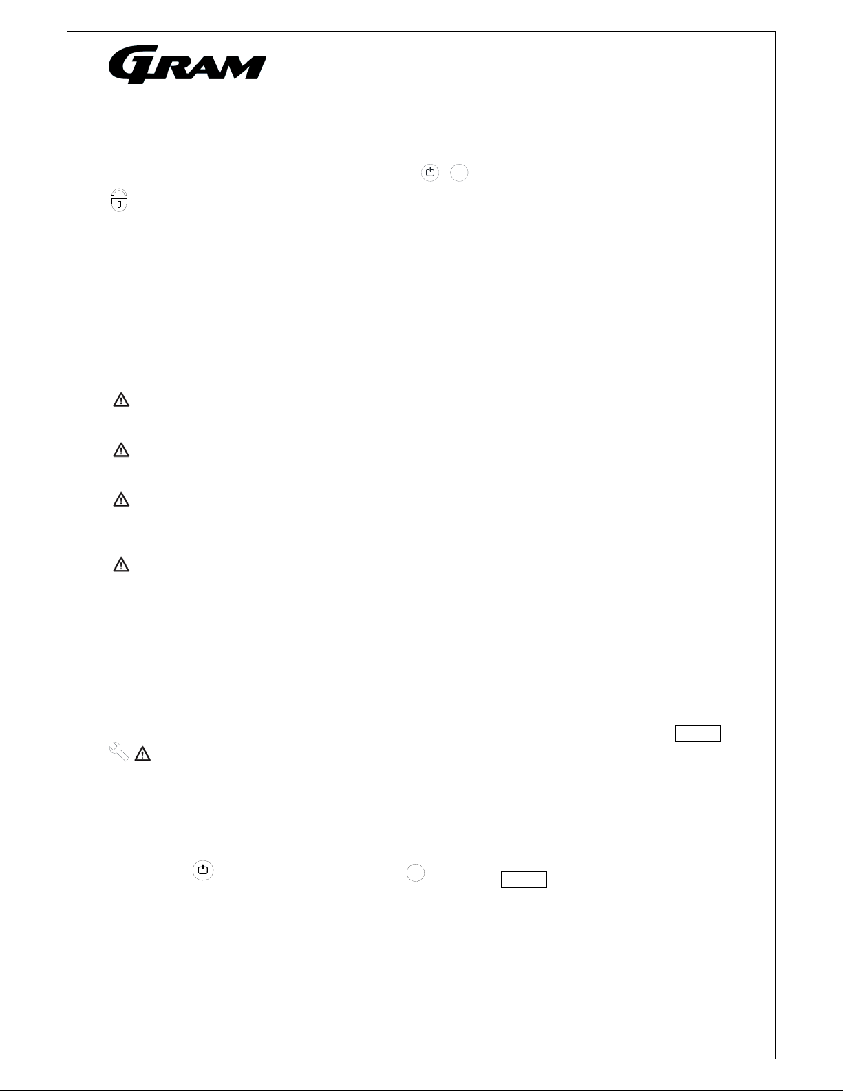
Gram ECO Service manual

765041642 1
Operating- and servicemanual
Gram Eco / Superior

765041642 2
Content
MPC 46 and the menus. 3
When servicing the product. 4
Start-up sequence 4
Defrosting 7
Temperature control and regulation: 7
Keylock 8
Error codes 8
Reminder of cleaning the condenser air filter 8
Resetting the FILTER alarm 8
Compressor counter time setting 9
Reset to factory setting 9
User menu 10
Visual and acoustic settings 12
Settings for running cycle 13
Test program for relays and electrical components 15
Display of current sensor inputs 16
Reset the controller to factory setting 16
Parameter settings in commercial program variants 17
Changing door hinge side. 18
Plug connections onboard the controller 28

765041642 3
MPC 46 and the menus.
The menus are divided up in two main menus.
A menu for presentations of values in the display and
settings for alarms parameters, and another menu for
technical, practical or physical settings to a normal
refrigerator or freezer.
In each main menu there exist smaller submenus.
These submenus are divided up in specific menu for kind of
cycles as defrosting or the settings for running the
evaporator fan.

765041642 4
When servicing the product.
Make sure the appliance is switched off at the socket before service is performed on electrical
parts. It is not sufficient to switch off the cabinet by the START/STOP key as there will still be
voltage to some electrical parts of the cabinet.
Start-up sequence
When the product switches ON, the software is loaded into the MPC-46.
The display shows multiple informations, see below:
TextDisplay
Second0‐3:
Softwareisloaded
intoMPC‐46on
start‐up
Allsegmentslightupwhite.Control,iseverythingok?
Thedisplayhasrecognizedversion3.0andawaitsmoreinformation….
Approx.3rdsecond
and3‐4seconds
forward:
NowtheMaxidisplayrecognizesprogrammevariantF3+version3.0.
Thedisplayrecognizesthattheproductisequippedwithone
compressor.
Approx.7thsecond
and3‐4seconds
forward:
Thedisplayrecognizeswhichcontrollampsareneededaccordingto
theprogrammevariantF3+,andtheappropriatelampsarelit.The
versionnumberisdisplayed.
Approx.10th
secondand3‐4
secondsforward:
Allcontrollampsareturnedoff,exceptthecompressorlamp.The
largedisplayisdisplayedreadyforuse.

765041642 5
Start up after power on – hot product.
On hot products or if the product has just been unpacked and connected to mains power, the temperature is
so high that the defrosting cycle is cancelled, and refigeration starts immediately.
Because the product has not been running before, the setpoint is displayed and not the current temperature.
TextDisplay
Normaloperation
afterstart‐upphase
hasended
Only+5°Cisdisplayed,whichisthestandardsetpointfora
refrigerator.
Situation1:
Refrigerator
Lessthanasecond
latercompressor
starts.
Thecompressorstarts.Thecoloriscyan,andlightsconstantly.
Situation2:
Extended
refigerator
Lessthanasecond
latercompressor
starts.
Thecompressorstarts.Thecoloriscyan,andlightsconstantly.
Situation3:
Freezer
Lessthanasecond
latercompressor
starts.
Standardsetpointforafreezeris‐18°C.Thecompressorstarts.The
coloriscyan,andlightsconstantly.

765041642 6
Start up after power on – cold product.
On cold products, or if the product has been turned off for a short while, and the evaporator temperature is
still below the freezing point, a defrosting cycle will be activated, and refrigeration starts later.
Because the product has not been running before, the setpoint is displayed and not the current temperature.
TekstMaxiDisplay
Normaloperation
afterstart‐upphase
hasended
Only+5°Cisdisplayed,whichisthestandardsetpointfora
refrigerator.
Situation1:
Refrigerator
Lessthanasecond
later,defrosting
starts,andusesthe
evaporatorfanfor
thedefrosting
process.
Becausedefrostingisrunning,butwithevaoratorfan,bothcontrol
lampsarelit.
Defrostmode:Air(Evaporatorfanrunning100%)
Situation2:
Extended
refrigerator
Lessthanasecond
later,defrosting
starts,andusesthe
evaporatorfanfor
thedefrosting
process.
Becausedefrostingisrunning,butwithevaoratorfan,bothcontrol
lampsarelit.
Defrostmode:Automatic(Controllerselectsacc.tosetpointwhether
fanorelectricalheateristobeused.)Ifelectricaldefrostingis
selected,thecontrollampforfanwillnotlightup
Situation3:
Freezer
Lessthanasecond
later,defrosting
starts,andusesthe
electricalheater.
Defrostmode:Electrical(Heaterbelowevaporator)

765041642 7
Defrosting
The defrosting cycle runs 4 times each day. If the cabinet is operating under severe load (frequent door
opening and frequent replenishment) manual defrosting can become necessary.
To start manual defrosting: Push for more than 3 seconds.
Refrigerator: Control lamps for fan and defrosting light up.
Extended refrigerator: Control lamp for defrosting light up, and lamp for fan light up depending on
setpoint.
Freezer: Control lamp for defrosting light up.
Shortly after defrosting has ended, the compressor starts, and the compressor symbol lights blue.
The number defrosts can be changed. See chapter ”User menu”.
Temperature control and regulation:
Keep pressed. When doing this, the setpoint temperature is displayed. While is kept
pressed, the setpoint can be changed by pressing or .
Each time or is pressed the temperature will change one degree. The new value flashes in
the display
When the required setpoint has been set, let go of the keys, a short beep sounds, and the settings
are saved.
P +
P P
+-
+-

765041642 8
Keylock
The keypad can be locked by simultaneously pushing for more than 5 seconds.
lights to indicate that the keys are locked, and a short beep sounds. Now it is not possible to use the
keys for temperature setting etc.
The same code is to be used for unlocking the keypad again.
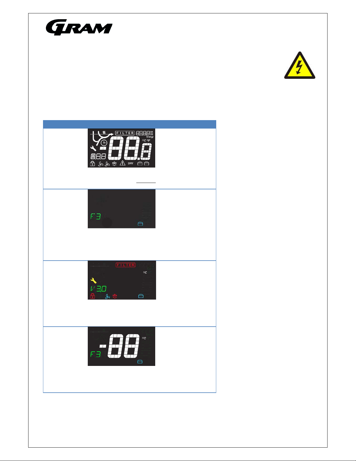
Error codes
OP
The door is open. The alarm system is activated, if the door is not closed within a certain time. The user
is reminded that the door is not properly closed.
F1
Cabinet sensor error. In the meantime the cabinet itself will maintain the set temperature by the
memory of the controller. Service assistance is required.
F2
Evaporator sensor error.
The cabinet will keep running until the error has been mended. Service assistance is required.
F3/F4
Condenser sensor error. The cabinet will keep running, until the error has been mended. Service
assistance is required.
Applies only to cabinets with built-in compressor.
F7
Indicates that the condenser temperature is too high. The cause might be a clogged condenser, or too
high ambient temperature.
If the condenser or air filter needs cleaning, the cabinet must be disconnected at the mains power.
Cleaning of the condenser is done with a brush or a vacuum cleaner.
The air filter can be removed and cleaned in a dishwasher at max. 50C.
If the ambient temperature is too high, the placement of the cabinet might be wrong, and an alternative
place should be found. Ventilation might help.
If this does not help, request service assistance.
Applies only to cabinets with built-in compressor.
Reminder of cleaning the condenser air filter
After 600 compressor running hours the filter must be cleaned and it is indicated by warning lights: FILTER
.
If the cleaning is not completed within 650 hours, the warnings continue, and an acoustic alarm sounds.
Resetting the FILTER alarm
After cleaning the air filter, the controller must be reset to remove the alarms.
It can only be reset by using a certain key combination.
Push three times followed by pushing three times. FILTER alarm will disappear after 1
minute.
+1
P

765041642 9
Compressor counter time setting
The default time value for the compressor counter is 600 hours.
The value can be changed i intervals of 50 hours.
Minimum value = 200 hours
Maximum value = 2000 hours
To change the value, proceed as follows:
Keep keys and pressed for 3 seconds.
The FILTER indicator flashes, and the value 600 is displayed.
Press the key, until the right value is displayed.
Press to confirm the setting.
The FILTER indicator is turned off.
Reset to factory setting
To reset the controller to factory setting:
Press + + for at least 5 seconds.
RES flashes in the display.
Press to confirm, RES lights up for 2-3 seconds, and the buzzer gives a short signal.
The controller then returns to normal display.
+
P

765041642 10
User menu
Push on and buttons at the same time in more than 3 sec. and the first Setup menu appears in the
display.
With and buttons its possible to look through each menu items in the “User menu”. Push on button
to activate the desired item and adjust the setting with and buttons.
To confirm the new setting, push button. Leave the menu item and user menu with the button.
Menu access P+1
Dry refrigeration DC Activation of dry refrigeration. [ON/OFF]
Rapid thaw UF Activation of rapid thaw. [ON/OFF]
Local alarm setting LAL LHL [° C] Setting the upper alarm limit. At alarm, the display shows: [
A
2].
LLL [° C] Setting the lower alarm limit. At alarm, the display shows: [
A
3].
Lhd [min.] Time delay for the upper alarm limit.
LLd [min.] Time delay for the lower alarm limit.
DA On/off Activation of local door alarm. At alarm, the display shows: [
A
1]. [on/off]
DAd [min.] Time delay for the door alarm.
BU On/off Activation of buzzer. The buzzer sounds at alarms [ A1], [
A
2], [
A
3].
[1=on / 0=off]
External alarm
setting
EAL EhL [° C] Setting the upper alarm limit At alarm, the display shows: [
A
4].
ELL [° C] Setting the lower alarm limit . At alarm, the display shows: [
A
5].
Ehd [min.] Time delay for upper alarm.
ELd [min.] Time delay for lower alarm.
DA On/off Activation of local door alarm. At alarm, the display shows: [
A
1]. [on/off]
DAd [min.] Time delay for the door alarm.
BU On/off Activation of buzzer. The buzzer sounds at alarms [ A1], [
A
4], [
A
5].
[1=on / 0=off]
ALL Activation of escorting alarm limits. [FAS]= fixed limits / [ESC] = limits following
the setpoint.
DEF Number of defrosts in 24 hours.

765041642 11
User menu overview:
PP
+/-
5
+
-
P
LAL
P
+/-
+
-
P
5
LHL 5
25
5
LHd 5
5
5
24
5
4
P
+/-
P
5
DA 5
OFF 5
On
+
-
P
+/-
P
5
DAd 5
55
4
+
-
P
+/-
P
5
BU 5
OFF 5
On
PP
+/-
5
+
-
P
EAL
P
+/-
+
-
P
5
EHL 5
25
5
ELL 5
25
5
24
5
24
P
+/-
P
5
EHd 5
55
4
+
-
P
+/-
P
5
ELd 5
55
4
PP
+/-
5P
CAL 5
CA 5
051
PP
+/-
5
ALL 5
FAS 5
ESC
PP
+/-
5
DEF 5
45
5
PP
+
P>3 sek.
1++/-
5
DC 5
OFF 5
ON
DRY
PP
+/-
5
UF 5
OFF 5
ON
1 x 2 x
2 x
3 x
2 x
2 x
2 x
3 x
3 x
3 x
3 x
3 x
3 x
3 x
3 x
+
-
+
-
+
-
+
-
+
-
+
-

765041642 12
Visual and acoustic settings
Push on and buttons at the same time in more than 6 sec. and the menu item [ A ] appears in the
display.
With and buttons it’s possible to look through the main menu item [ A ] and [ P ]. Push on button to
enter the submenu from the main menu items.
With and buttons it’s possible to look through the submenus menu items. Push on button to enter
the desired menu item and adjust the setting with and buttons.
To confirm the new setting, push button. Leave the menu item and submenu with the button.
Menu access P+2
Alarm setup A A1 [° C] In case of condenser overheat, compressor protection cycle is started.
A2 [° C] Condenser temperature, which disconnects the compressor protection
cycle.
A3 [min]. Re-enter time for acoustic alarm (min.)
Display
presentation
P P1 [min.] Temperature freeze after defrosting end.
P2 [° K] Temperature freeze around setpoint. Temperature fluctuation filter.
P3 [sec.] Display updating frequency.
P4 Selection of Celsius or Fahrenheit temperature scale.
+
P>6 sek.
2+
1 x
PP
+/-
5
+
-
P
A
P
+/-
+
-
P
5
A1 5
65
5
A2 5
40
5
64
5
41
P
+/-
P
5
A3 5
55
4
3 x
3 x
3 x
PP
+/-
5
+
-
P
P
P
+/-
+
-
P
5
P1 5
30
5
P2 5
3
5
31
5
4
P
+/-
P
5
P3 5
10 5
11
3 x
3 x
3 x
+
-
P
+/-
P
5
P4 5
C5
F
3 x
+
-

765041642 13
Settings for running cycle
Push on and buttons at the same time in more than 6 sec. and the menu item [ C ] appears in the
display.
With and buttons it’s possible to look through the main menu item [ C ], [ F ] and [ d ]. Push on
button to enter the submenu from the main menu items.
With and buttons it’s possible to look through the submenus menu items. Push on button to enter
the desired menu item and adjust the setting with and buttons.
To confirm the new setting, push button. Leave the submenu and main menu item with the button..
Menu access P+3
Compressor setup C C1 [° K] Differential for compressor cut-in and cut-out.
C2 [° C] Highest allowed temperature limit for the cabinet.
C3 [° C] Lowest allowed temperature limit for the cabinet.
C4 [min] Forced pause time for compressor between cut-out and cut-in.
C5 Number of condenser sensors connected.
C6 [min] Compressor stop by open door.
C7 [° K] Soft differential for cool/heat cut-out (kelvin)
C8 [° C] Setpoint for condenser fan
C9 [° K] Cut-out differential for condenser fan (kelvin)
Evaporator fan F F1 [° C] Temperature allowing the evaporator fan to start after defrosting.
F2 [min.] Pause time of evaporator fan, while the compressor is stopped.
F3 [sek.] Running time of evaporator fan, while the compressor is stopped.
F4 [° K] Stop temp. of LT compressor i cascade evaporator (celcius)
Display presentation D D1 Number of defrosts / 24h
D2 [° C] Defrost stop temperature measured at the evaporator.
D3 On/off Activation of defrost by start-up sequence [1=on / 0=off].
D4 [min.] Maximum defrosting time.
D5 Selection between automatic- [1], air- [2] or electric defrosting [3].
D6 [min.] Dripping time after defrosting
D7 [° C] Temperature limit deciding the defrosting method, when d5 = [1]
D8 [° C] Evaporator temperature starting an extra defrosting cycle.

765041642 14
+
P>6 sek.
3+
1 x
PP
+/-
5
+
-
P
C
P
+/-
+
-
P
5
C1 5
5
5
C2 5
12
5
4
5
13
P
+/-
P
5
C3 5
25
3
3 x
3 x
3 x
PP
+/-
5
+
-
P
F
P
+/-
+
-
P
5F1 5-1
5
F2 5
5
5-1
5
4
P
+/-
P
5
F3 5
60 5
50
3 x
3 x
3 x
+
-
+
-
P
+/-
P
5
C4 5
55
4
3 x
+
-
P
+/-
P
5
C5 5
152
3 x
+
-
P
+/-
P
5
C6 5
15
2
3 x
+
-
P
+/-
P
5
C7 5
-5
-
3 x
+
-
P
+/-
P
5
C8 5
35 5
35
3 x
+
-
P
+/-
P
5
C9 5
55
4
3 x
PP
+/-
5
+
-
P
D
P
+/-
+
-
P
5
D1 5
4
5
D2 5
7
5
5
5
8
P
+/-
P
5
D3 5
05
1
3 x
3 x
3 x
+
-
P
+/-
P
5
D4 5
30 5
31
3 x
+
-
P
+/-
P
5
D5 5
25
3
3 x
+
-
P
+/-
P
5
D6 5
05
1
3 x
+
-
P
+/-
P
5
D7 5
253
3 x
+
-
P
+/-
P
5
D8 5
-35 5
-34
3 x
+
-

765041642 15
Test program for relays and electrical components
Push on and buttons at the same time for more than 6 sec. and the menu item [ tC ] appears in the
display.
Note: When this test program is started, all outputs are de-activated, which means the cabinet is turned off.
It might be experienced that the compressor does not start again after leaving the program, because the
compressor protection “forced pause” takes effect.
With and buttons its possible to look through each menu items in the “Service program”. Push on
button to activate the desired relay and the display glows with [ on ]. The desired relay conducts now power
to the electrical component.
Push the button to switch off the power from the electrical component. Leave the service program with the
button.
Menu access P+4
P-key [on]
Compressor TC Comressor is running, and if a condenser fan is present, it runs too.
Evaporator fan TF Evaporator fan is running
Defrost heater Td Defrost heater is turned on. Warning: the heater might be very hot. Danger of
burn!
Light Tl Light is switched on.
Alarm output TA Activation of voltage free contact. Alarm output.
Display test TdP All LED’s light up for 1 sec. and the buzzer sounds. Then the software revision
number is displayed.
+
P>3 sek.
4
+
-
P
+
-
P
5
TC 5
ON
5
TF 5
ON
P
5
Td 5
ON
+
-
P
5
TL 5
ON
+
-
P
5
TA 5
ON
+
-
P
5
TdP 5
ON

765041642 16
Display of current sensor inputs
Push on and buttons at the same time in more than 6 sec. and the menu item [ P-A ] appears in the
display.
With and buttons its possible to look through each menu items to check each sensor in the cabinet.
Push on button to activate the actual sensor and the display shows the actual temperature.
Leave the program with the button.
Menu access P+5
P-key [° C] Display message and
cause
Room senso
r
P-
A
Room sensor measurement is displa
y
ed F1 Room sensor error
Evaporator sensor P-b Evaporator sensor measurement is displayed F2 Evap.sensor error
Condenser sensor
1
P-C Condenser sensor 1 measurement is displayed F3 Condenser sensor 1
error
Condenser sensor
2
P-d Condenser sensor 1 measurement is displayed F4 Condenser sensor 2
error
*
An overheated condenser could be caused by a clogged air filter. Can be
triggered by both C and d sensor.
F7 Overheated
condenser 1 and 2
By open door this symbol is displayed. In event of a too long door opening,
an alarm is triggered [ A1].
-0- Open door symbol
Reset the controller to factory setting
To reset the controller to factory settings:
Push + + for more than 6 seconds. The display shows [ RES ].
Push , and a beep sounds for confirmation”.
+
P>6 sek.
5
+
-
P
+
-
P
5
P-A 5
5
5
P-b 5
5
P
5
P-C 5
5
+
-
P
5
P-d 5
5

765041642 17
Parameter settings in commercial program variants

765041642 18
Changing door hinge side.
The door can be changed from left hand-hinged to right hand hinged or vice versa.
Example: Changing from right hand to left hand hinged door.
Disconnect the cabinet from mains power !
1

765041642 19
2

765041642 20
3
Other manuals for ECO
1
This manual suits for next models
11
Table of contents
Other Gram Refrigerator manuals

Gram
Gram KF 3255-93/1 User manual

Gram
Gram KF 4386-90 FN/1 User manual

Gram
Gram KF 310-01 User manual

Gram
Gram KFI 401754 N/1 User manual

Gram
Gram Compact 210 User manual

Gram
Gram FSI 110 User manual

Gram
Gram KS 4476-90/1 User manual

Gram
Gram KF 4376-90 FN X User manual

Gram
Gram KSU 3136-50 /1 User manual

Gram
Gram KS 220 User manual

Gram
Gram KF3135-90 User manual

Gram
Gram KS 32265-63 User manual

Gram
Gram KS 220 User manual

Gram
Gram FS 230 User manual

Gram
Gram KS 3215-93 X/1 User manual

Gram
Gram KS 3135-90 User manual

Gram
Gram FB 4200-90 User manual

Gram
Gram KF 3255-90 User manual

Gram
Gram KS 3215-50 User manual

Gram
Gram KFI 401754 N User manual