Grandview CB-MRC User manual

GRANDVIEW REPRODUCING GENUINE COLORS
ISO9001:2000
International Certification
Grandview Crystal Screen Canada Ltd.
#11- 3751 North Fraser Way,
Marine Way Business Centre,
Burnaby, BC, Canada V5J 5G4
Tel: 1-604-412-9777 Fax: 1-604-412-9796
Website: www.grandviewscreen.ca
Guangzhou Grandview Crystal Screen Co., Ltd.
P.O. 511400 Federal Ind. Zone No. 363, Yushan West Road,
Shiqiao, Panyu District, Guangzhou, Guangdong, China
Tel: +8620-8489-9499 Fax: +8620-8480-3343
Website: www.grandviewscreen.com
www.grandviewscreen.com.cn
GRANDVIEW REPRODUCING GENUINE COLORS
Thank you for purchasing a Grandview projection screen.
Before use, please read instructions carefully. After installation, store instructions for future reference.
Instruction Manual of
Mini Recessed Motorized Screen
Model:CB-MRC

Please read the below attention points before using
1-2mm >4 m m
Warnings Adjustment
Warning Constraint
Forbidden
1. Please hand over the screen to qualified professional for installation, non-qualified individual could cause damage
to the product or injury of people.
2. Please make sure that the installation position can suffer from at least 50 Kg, otherwise there could be a potential
dropping problem causing damage to the product or injury of people.
3. It is forbidden to connect the power before the installation is finished, otherwise it could cause damage to the
product or injury of people.
4. Wrong wiring of malfunction of the wire could cause damage to the product or inquiry of people, please hand over
the electric work to electric professionals.
5. The product is using Single-phase AC power, please use a socket with earth wire and make sure the earth wire is
well connected.
6. Please make sure the screen is installed in a level status, otherwise it could cause damage to the product.
7. For screen with IR control, please do not use it in places with strong light or laser. For screen with remote control,
please do not get close to fluorescent lamp, led lamp or other device or environment with strong electromagnetic
radiation, to avoid damage to the product.
8. In order to lower down the possibility of fire or electric shock, please do not expose the product in damp places.
9. Please keep the screen away from heating device such as heater, stove, etc.
10. As long as the plug is still in socket, the screen is still connected with AC power, please remove the plug during
lightening, thunderstorm or not used for extended periods.
11. Please retract the fabric fully in the case after using to avoid damage to the fabric by dust and dirt.
12. If the surface of fabric is dirty or being cut, it will affect the image quality, so please pay attention to below points:
A. Please do not touch the fabric with your hand
B. Please do not write or draw on the fabric
C. Please do not cut or poke the fabric to avoid damages
D. Please do not clean the surface with chemical cleaner, you can use dry cloth and soap water instead.
13. To avoid unnecessary damage, please use and manage the product by adult.
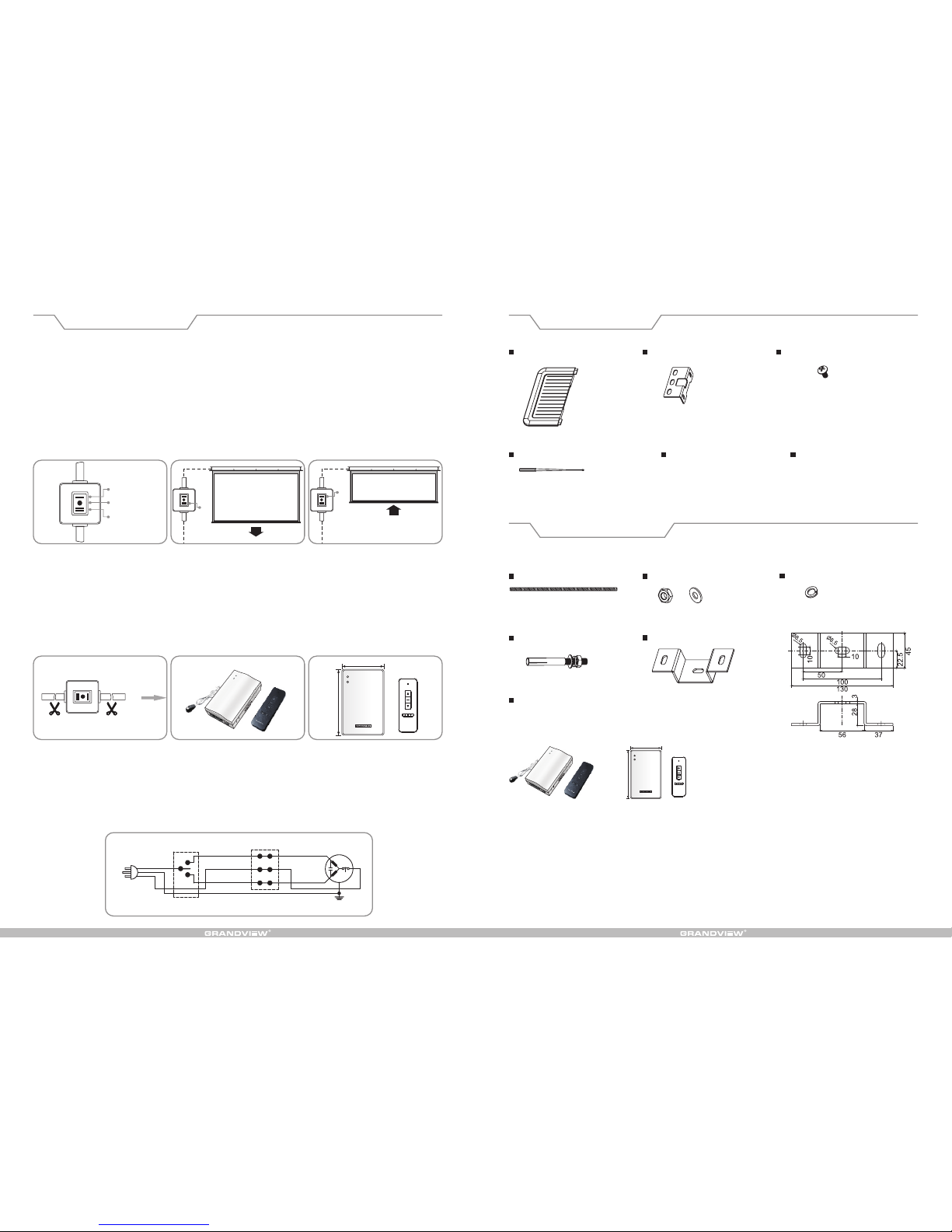
14. Please choose only the accessories from original factory.
15. Please do not hang any items under the case to avoid potential damages.
16. There are no spare parts inside for replace or repair, please contact the after sales team for after sales service.
17. Lubricant is not required for the motor.
Warning Constraint
Warning
Warning
Warning
Warning
Warning
Warning
Warning
Warning
Warning
Warning
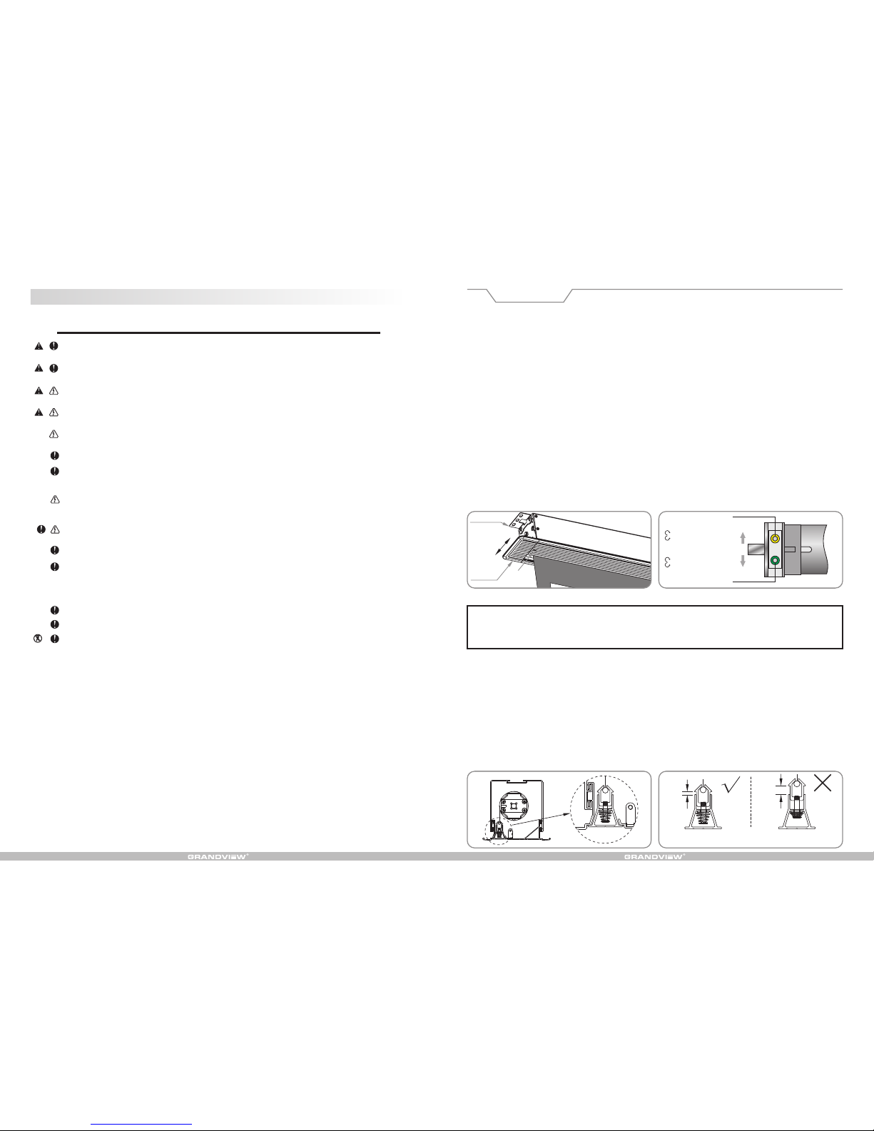
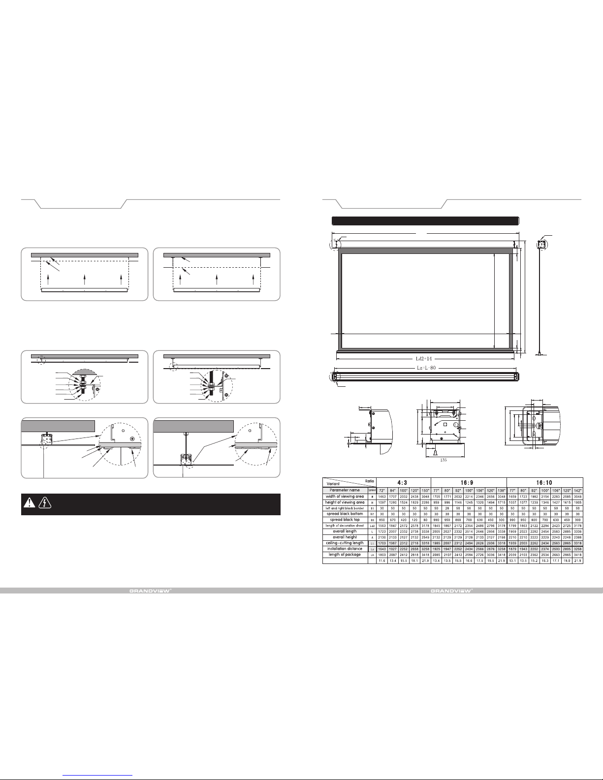
Instruction of adjusting the retraction and extension limit
1. The default retraction limits are perfect settings, we do not recommend adjustment to avoid potential damage to
the product, please talk to after sales team for further advice.
2. If you do need adjust the extension limit, you can do that through the slot underneath the right hand side of the
screen, with below instructions:
WARNING
Please pay attention when adjusting retraction. Over-retraction is avoided in order not to spoil the motor and
screen; please also pay attention when adjusting extension. The fabric should be rolled at least one and a half
rounds onto the shaft to avoid the fabric fall off. After the adjustment is done, the difference of retraction and
extension limit might not be found at once until the screen is operated for several times.
Adjustment of retraction (upper limit).
Press the "up" button of the controller and the screen would retract. When the fabric rod goes nearby or enters the
case, please insert the adjuster key (slight adjustment on direction is needed when insert adjuster key until the key
enter correctly into the green hole) into the positioner adjusting hole in green color on motor to make adjustment.
Stand opposite to positioner adjusting hole and turn adjuster key clockwise to make fabric extend slightly, while
turn counter clockwise to make fabric a little retraction for adjustment.
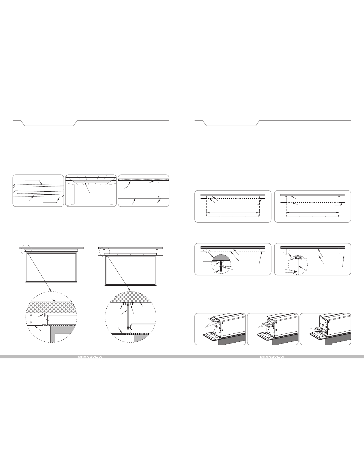
Note on upper limit adjustment:
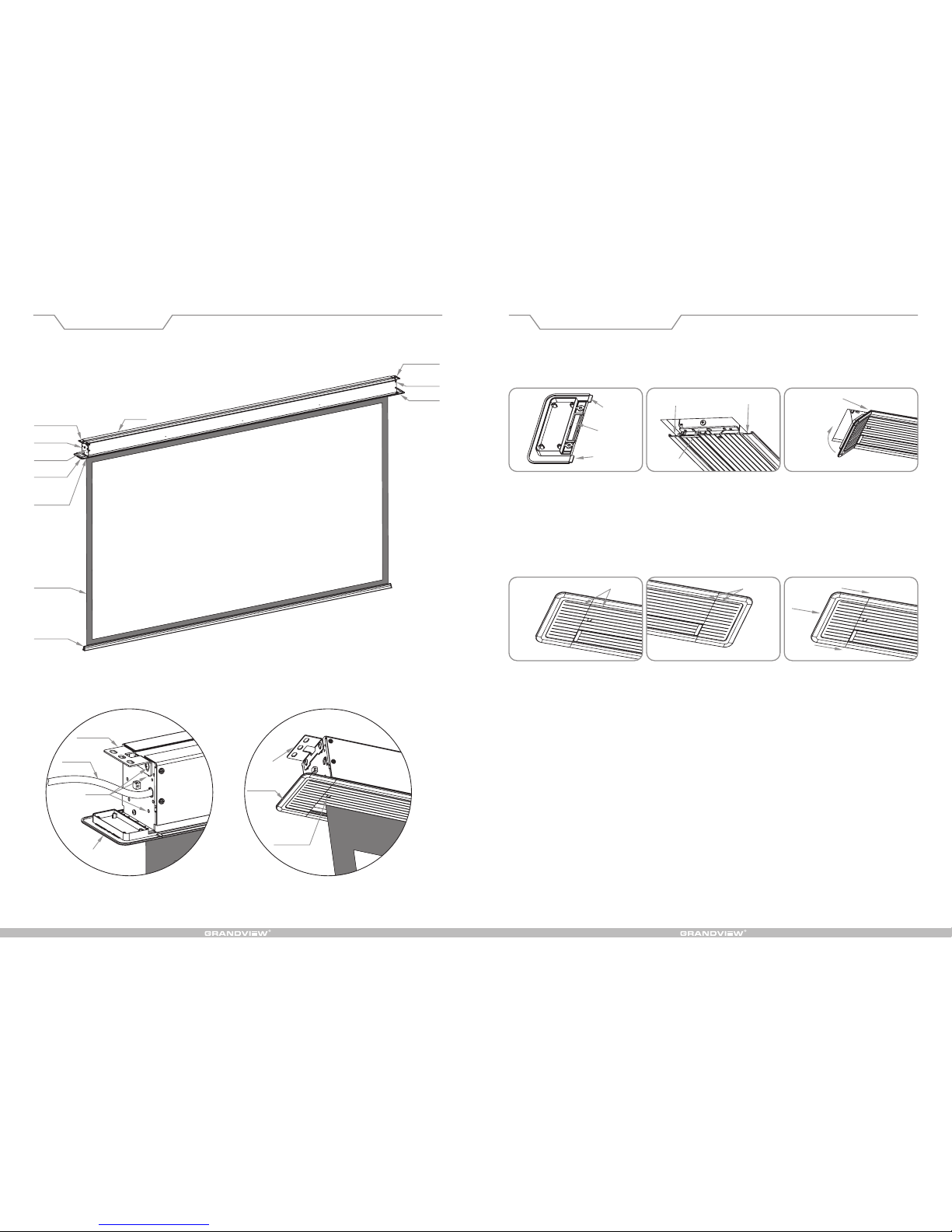
The decoration board of this product can completely cover the exit of the case and there is springs installed on the
integration of fabric rod, which is different from other series of screens.
When adjusting the upper limit, please make sure decoration board could be completely closed. Enough space is
needed for decoration board to move freely. Setting the upper limit to be too high would come to damage the
fabric or motor.
Adjustment of extension (lower limit).
Press the "down" button of the controller and the screen would extend. Insert the adjuster key into the positioner
adjusting hole in yellow color on motor to make adjustment. Stand opposite to positioner adjusting hole and turn
adjuster key clockwise to make fabric retract slightly, while turn counter clockwise to make fabric a little extension
for adjustment.
Due to the special structure of the product, default of "retraction limit" has been perfectly set and it is not
recommended to make adjustment by user so as not to damage the screen because of improper
adjustment on retraction limit. Any damage out of this operation is not under warranty for the product.
Diagram 32 Diagram 33
Ceiling bracket Yellow key hole
Front
Rear
Position of extension ( lower limit)
Adjust clockwise to m ove upward
Adjust clockwise to m ove downward
Adjust counter clockwise to
move upward
Adjust counter clockwise to
move downward
Position of retraction (upper limit)
Green key hole
Left
decoration
cap Lower limit
adjusting
hole
Front
Rear
Diagram 34
Proper
height
Improper
height
(upper
limit is set
too high)
Status of lower bar when retraction
(seen from side view) Diagram 35

AC 220~230V
50~60Hz,115 W
M
K1
78mm
128mm
18
上升
停止
下降
上升
停止
下降
Accessories Pack(s)
Optional Accessories
Operation Instruction
The motorized screen is standard with inline switch control, while external remote control is for your option.
1. Inline switch control (diagram 25)
Extension (diagram 26) Press "down" button on inline switch then the fabric would extend slowly till it reaches
the default position before it stops automatically.
Retraction (diagram 27) Press "up" button on inline switch then the fabric would retract slowly till it completely
enters the case before it stops automatically.
Stop Press "stop" button on inline switch in the course of retraction or extension to make
fabric stop at the position required.
2. External remote control and RS232/485 control:
If remote control or RS232/485 control is needed, please upgrade the control system by installing external remote
control kits (need to cut off the inline switch and reinstall the external remote control kits manually for alternative),
see diagram 28-30. Please turn to the manual for external remote control kits to know more details on usage and
wiring connection method.
Model available: External IR remote control kits (Third Generation)---Model: 1GD-IRAnⅢ
External RF remote control kits (Third Generation)—Model: 1GD-868MnⅢ.
;
Note:
Make sure the fabric is clean before retraction.
It is not recommended that continuous operation of retraction or extension be over 50 seconds. Over heat of the
motor due to operated continuously above 4 minutes would result the screen in protection status (stop working for
a while). In this situation, please stop operating the screen for a moment until motor is cool.
3. Circuit diagram
3. Circuit diagram
Decoration cap*2 pcs
(left and right)
Ceiling bracket*2 pcs M5*10 thumb head screw*4 pcs
M4 hexagonal adjuster key*1 pc
M8*500 extended bolt*2 pcs
M8*60 Expansion bolt*4 pcs
Spring gasket*6 pcs
External remote control kits ( with RS232/485 control function)
External IR remote control kits (Third Generation)---Model: 1GD-IRAnⅢ;
External RF remote control kits (Third Generation)—Model: 1GD-868MnⅢ.
Hook*2pcs
Dimension for installation of hook
M8 nut*8 pcs, gasket*8 pcs
Qualification certificate*1 copy Manual*1 set
Diagram 25
Up
Stop
Down
Diagram 27Diagram 26
Down
Up
Diagram 28 Diagram 30
Diagram 31
Diagram 29
Up
Common
Down
Yellow green
Brown
Blue
Black
7 8 m m
128mm

72
Product structure Installation Instruction
Case
Installation plate
Right trestle
Right cap
Left trestle
Power line
Left cap
Limit
adjusting
Fabric
Installation plate
Installation
plate
Power line
Left cap
lower limit
adjusting hole
Mounting hole
Left cap
Fabric rod
integration
Installation plate
10. Installation of left/right decoration cap. Insert the fixing legs (diagram 19) of decoration cap aslope into slots
from the two edges of decoration board (diagram 20). Please push upward tightly (diagram 21) and the decoration
cap would be attached to left/right trestles by magnet (see diagram 19-21).
Note:
Please make it clear the left and right decoration caps. Please pay attention to the decoration strip. After the
decoration caps are fixed, the decoration strips should be in line with those on the decoration board (diagram 22-
23)
If the seam seems too big at the joint, please push the decoration cap toward the screen to make it in position.
Fixing leg
Slot 1.Insertion into slot
2.Push
upward
tightly
left/right
trestles
Slot
Magnet
Fixing leg
Decoration strips in line Decoration strips in line Push the middle forward if seam is
too big at
the joint
Left decoration cap Right decoration cap
Diagram 19
Diagram 22
Diagram 21
Diagram 24
Diagram 20
Diagram 23

W
H
B1 B1
B3 B2
A
34
30
Ht=H+B2+B3
14
15
70
4
40
40
30
105
135
80
40
8.5
14.5
105
60
15
60
10.5
120
4
36
Installation Instruction Framework and Dimension
6. Lift the screen and put it into the mounting holes pre-drilled. The fixing holes on two ends of installation plate
should align to the expansion bolts or extended bolts on ceiling, see diagram 13-14.
Note: This step must be completed by two installers who should hold two ends of screen respectively when
installation.
7. Please put gasket, spring gasket and nut through the bolt, twist the nut for several rounds but not fasten it
(diagram 15-16), and adjust the position of the nuts above and below the installation plate to get the front and
back part of decoration board close enough to the decoration ceiling. Then please fasten the nut below the
installation plate, see diagram 15-18.
Warning:
Any installation of the screen related to electrical operation must be done by qualified electrician,
or it is likely to damage the product or property lost and casualty.
Note:
Before connecting the products to power supply, please make sure the put-in voltage is in conformity with rated
voltage of the product. It is recommended that supply power should be 2 times or above as much as the rated
power of the product. Any improper power supply would lead to abnormal performance or even spoil the product.
8. Please fix the inline switch or external remote control receiving box where it is convenient to get access to. Then
plug in the socket to connect to power supply.
9. Operate the screen to complete retraction and extension for once or twice to see if it is working normally before
moving to next step of installation.
Note:The screen must be operated in level condition. Please make necessary adjustment for screen to be
horizontal when installing, or it would be likely to do damage to the screen.
Concrete ceiling
Mounting hole
Lift upward
Fabric
Nut
Decoration ceiling Decoration ceiling
Back part of
decoration board
Front part of
decoration board
Front part of
decoration board
Adjust to be flat
and smooth
Adjust to be flat
and smooth
Nut
Installation plate Installation plate
Nut Nut
Expansion bolt Extended bolt
Gasket Gasket
Gasket Gasket
Spring gasket Spring gasket
Fabric
Mounting hole
Lift upward
Concrete ceiling
L
Check to details A
Check to details B
Check to details C
Installation distance: Lz=overall length(L)-80mm
Ceiling-cutting dimension: length (Lt)=overall length(L)-20, 115mm in width, 120mm plus in height
Electrical data: AC220-230V/50-60Hz, 0.48A, 115W.
Any change on function, structure or specification is without prior notice due to improvements on the product.
Please refer to the specific product included.
Details B
Details A Details C
Mounting hole-1
Mounting hole-2
GND hole
Power cable
Mounting hole-3
33(reference range
changed according
to height of fabric)
Diagram 13 Diagram 14
Diagram 15
Diagram 17
Diagram 16
Diagram 18
Gross Weight (kg)

H
H
54
Installation Instruction Installation Instruction
This product is fit to install into all types of decoration ceilings. User could install the product according to different
environments. The screen should be installed at the most proper place where it can work with projector. It is more
convenient and safer for use when the screen is installed right and correctly.
Please unpack the packages and check if the fittings are correct in number and types. Please install the screen at
proper place according to the installation instructions below.
1.Ceiling-cutting should be done at the position where the screen would be installed (diagram 1). The dimension of
ceiling-cutting is 115mm in width, while it is 20mm shorter than the overall length. As to the grille ceiling, please
take some pieces out of the ceiling (diagram 2) and cut them into pieces that would fit to the ceiling for re-
installation after installation of the screen is finished.
2.Please measure the height between surfaces of concrete ceiling and decoration ceiling (diagram 3) for optional
installation modes:
A. If the “H” is about 120mm, please install the screen directly onto concrete ceiling, see diagram 4;
B. If the “H” is above 120mm, optional accessories including the hook and extended bolt are needed
to complete installation, see diagram 5.
Concrete ceiling
Ceiling-cutting
Concrete ceiling
Expansion bolt
Concrete ceiling
Extended bolt
(optional
accessory)
Extended bolt
and hook
(optional accessory)
Expansion
bolt
Decoration
ceiling
Screen
Diagram 4 For installation to low ceiling Diagram 5 For installation to high ceiling
Diagram 1
Screen
Decoration ceiling
Removing some pieces
of decoration ceiling
Surface of ceiling
Surface of
decoration ceiling
Decoration ceiling
Concrete ceiling
Diagram 2 Diagram 3
Decoration
ceiling
Note: Please make sure the concrete ceiling is strong enough to be bear the weight of 50kg or above before
starting installation in order to avoid any damage on product or property lost and casualty due to insufficient
bearing.
Note: Installation of the product must be completed by qualified technician(s), or it would result in damage,
property lost and casualty.
3.According to the installation modes, please drill holes on concrete ceiling and fix expansion bolt (
not included) in model of M8*80 or longer one into the holes, see diagram 6 and 8; for high ceiling
installation, hooks and extended bolts are needed to work with M8*60 expansion blot (optional
accessories), see diagram 7 and 9;
4.Both of the installation modes need to put the extra M8 nuts and gaskets for adjustment on the height of
installation, see diagram 8-9;
5.Choose the sets of mounting holes for fixture according to the installation mode selected. Please use the M5*10
screws included in fitting pack to fix the screen. If the extended bolts are not needed in installation, please choose
the first set of mounting holes for fixture, see diagram 10; for installation to high ceiling where extended bolts are
applied, please choose the second or third set of mounting holes according to installation environment. It is
recommended to choose the third set of mounting holes if the extended bolts are long enough to reach because it
is easier for installation, see diagram 11-12.
Note: The center distance of two holes drilled for suspending purpose should strictly follow the actual dimension of the product, or the
installation is not likely to be done; the distance from the two holes drilled for suspending purpose to both ends of the decoration
ceiling should be the same. The suspending (installation) distance equals overall length of screen minus 80mm, please refer to the
specification diagram for details.
Concrete ceiling Concrete ceiling
Ceiling-cutting (slot) Ceiling-cutting (slot)
Suspending (installation) distance Suspending (installation) distance
Decoration
ceiling
Decoration
ceiling
Diagram 6 Use screws for installation to low ceiling Diagram 7 Use hook for installation to high ceiling
Gasket
Spring gasket
Nut
Expansion bolt
Nut Nut
Concrete ceiling
Expansion
bolt
Hook and
bolt
(optional
accessory)
Concrete ceiling
Ceiling-cutting
(slot)
Extended bolt
(optional accessory)
Ceiling-cutting
(slot)
Decoration ceiling
The first set
of mounting
holes
The second set
of mounting
holes
The third set
of mounting
holes
Gasket Gasket
Diagram 8 Use screen for installation to low ceiling
Diagram 10 Diagram 12Diagram 11
Diagram 9 Use hook for installation to high ceiling
Decoration
ceiling
Table of contents
Other Grandview Accessories manuals

Grandview
Grandview FA-MIxx II User manual

Grandview
Grandview CN Series User manual

Grandview
Grandview CNV Series User manual

Grandview
Grandview FA-MIxx II User manual

Grandview
Grandview Large Stage Series User manual

Grandview
Grandview CB-MI Series User manual

Grandview
Grandview FA-MR series User manual

Grandview
Grandview CR-Mxx User manual

Grandview
Grandview FANCY Series User manual

Grandview
Grandview GRIPRC92H User manual