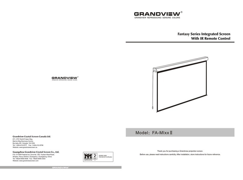
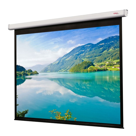
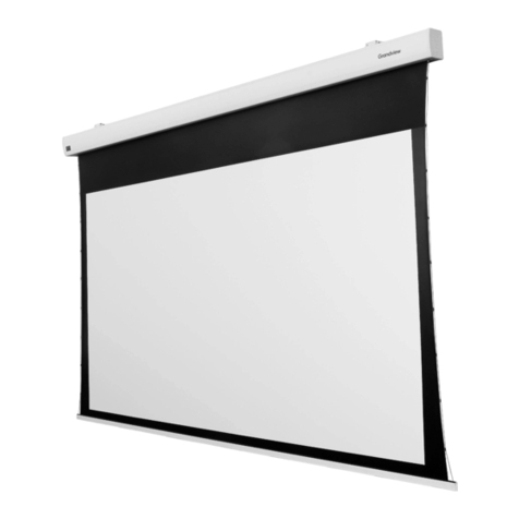
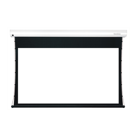
Grandview FA-MIxx II User manual


230V/120V/100V 50Hz/60Hz 90W/80W
Motorized Screen Power Specifications
Voltage Frequency Watts Application
Applies to motorized screen up to 120"
Allen key (1pc)
Remote
(1pc)
Controller
External IR receiver (1 )pc
Description
Accessories
Trigger line ( 1pc )
Floating mounting bracket (2pcs)
5 40mm Tapping screw & cap (8sets)
M5x10 Screw (6pcs)
Ceiling hanger (2pcs)
Floating mounting bracket
Aluminum casing
Screen fabric
Bottom Rod
Top panel
Upper groove
Locking piece
Lower groove
Locking screw
Please read theseimportant safety instructions
Read and understandall instructions beforeinstalling and usingthe projection screen.
Always connect thisprojection Screen toa grounded outlet.The power outletshould be located
near the Screenand shall beeasily accessible.
This equipment mustbe supplied froma power systemproviding a PROTECTIVEEARTH
connection and havinga neutral connection,which can bereliably identified.
Always ensure thatthe unit isproperly earthed andpower connections correctlymade.
Toreduce the riskof electric shock,do not disassemblethis projection screen,but take itto a
qualified serviceman whenservice or repairis required. Incorrectreassembly can resultin
electric shock whenused.
Close supervision isnecessary when Projectionscreen is inuse by ornear children. Donot
leave Screen unattendedwhile is use.
Installer must ensurethat the mountingstructures and fastenersmust be ofadequate strength
to securely supportthe screen sothat vibrations oreven abusive pullingon the screensurface
will not causethe housing towork loose orfall.
Do no operatescreen with adamaged cord orif the screenhas been droppedor damaged untilit
has been examinedand repaired bya qualified serviceman
DO not placeor attach anythingto metal casingor viewing surfaceof the screen.
Position cord sothat it willnot be trippedover, pulledor in contactwith hot surfaces.
DO not plugthe cord withwet hands; electricshock could occur.
Save those instructions
10

2
Installation
Figure 1
Wood wall installation Wood ceiling installation Concrete wall installation Concrete ceiling installation
Figure 2 Figure 3 Figure 4 Figure 5
Wall and Ceiling MountInstallation
Installation Steps:
1.Wood wall and ceiling installation: Drill in the 5 x 40 screws through the appropriate holes in the bracket
(figure 2-3)
2.Drywall and ceiling installation: Install the anchors and drill in the 5 x 40 screws into the appropriate
bracket holes (figure 4-5)
Take out all the parts from the package and following the accessories guideline ensure all the parts are there.
There are three different types of installation available for this product: wall mount, ceiling mount or ceiling hang.
Depending on the installation environment, the floating mounting brackets can be installed at various points for your
convenience. However, the ideal position for the mounting brackets is closer to the endcap as this will reduce
vibration and noise.
1.According to the surface of installation, choose the appropriate screws needed for mounting (regular screws for
wood surfaces, tapping screws for concrete surfaces)
2.Mount the brackets onto the surface, ensuring it is level (tip: draw a erasable level line when mounting the
brackets). See below for picture description (figure 1):
9
When the plug on power cord is used as disconnect device, the socket-outlet shall be installed near the
equipment and shall be easily accessible
Attention:
> Please make sure there isno dust or dirt on thefabric surface before rolling it backto the casing
> The recommened working timeis less than 50 seconds.The motor will enter overheating protection
status and stop working for everycontinuous 4 minuters operation, user wouldneed to wait for a
while until the motor cool downbefore operating again.
> There is no lubeneeded for the motor.Please be noticed that the appropriatesetting is optimized
which requires no further adjustment, pleaseconsult the after sales team beforeadjusting the limits.

3
Up groove
Down groove
Figure 8 Figure 9 Figure 10
Figure 11
Figure 6 Figure 7
Figure 12
Locking screw Locking piece
3.Loosen the lockingscrew to lowerthe locking piecedown all theway (figure 6-7)
4.When mounting thescreen onto thefloating mounting brackets,ensure the grooveson the screen
casing match upwith the upperand lower groveson the brackets.Simply slide in,and bracket's grooves
will hold thecasing in place.Horizontal adjustments canstill be made(figure 8-10).
5.Tolock the screenin place, closeand tighten thelocking screw onthe mounting brackets.This will keep
the screen casinglocked firmly inplace (figure 11-12).
8
Other Options Connection Diagram
. Function Destription for convertion from FM to IR Control
When you insert the Wireless Synchro Convertor Receiver into EXTIR plug of the screen(Figure 45), you can
use FM wireless remote control device. The Intelligent Synchro Power Supply Control Adapter(for all projectors),
with 12V wireless trigger (for projectors with trigger output), can synchronously control the screen. (Figure 46-47)
Wireless Synchro
Convertor Receiver
Figure 45
Intelligent Synchro Power
Supply Control Adapter
. External Wall Switch
Manual control for screen up/stop/down.
Figure 48
Intelligent control for screen up/stop/down when
connected to the intelligent interface of the screen.
Intelligent control for screen up/stop/down when
connected to the computer's RS232 or USB
interface
Figure 49
Figure 46 Figure 47
External Intelligent Wall Switch Connection

7
Externd IR sensor
Automatic Trigger Control Description
3.You can remove the 12V trigger wire if there is no need.
1.Insert one end of trigger into the trigger jack at left side of screen's end cap TRIG (Figure 22),, and insert another
end into 12V output hole.
2.When the projector is running, screen fabric will go down automatically; when the projector is closed, screen fabric
will retreat automatically.
External Controls (Central Control or RS232, Grandview Wall Switch) Function
Plug one side of the signal cord into the computer output jack at left side of the screen's end cap, the other side of
the singal cord to the Central Control jack, RS232 or Grandview Wall Switch (Figure 41-42), and then you can
control the up/stop/down of the screen via central control or computer.
IR Remote Control Function
1.When nothing blocks the sight of IR window, you can use the controller to control the screen (Figure43).
2.For hidden installation or IR window is blocked by something, please take out the External IR Receiver and plug
its head to the revelant hole, and then fix it at the position where IR signal is available. (Figure 44)
Figure 41 Figure 42
Figure 43 Figure 44
Figure 39 Figure 40 4
A
12
Figure 13
Figure 14 Figure 15
Figure 16 Figure 17
Figure 18
4.After completing steps2 and 3,check to seewhether the wallbracket is securelyfixed onto thehousing
of the screenbefore hanging. Hangscreen as shownbelow. (figure18)
Ceiling Hang Installation
Choose tapping screwswith hangers (orother screws withhangers, not provided)according to your
ceiling material. 5x 40mm forwood ceilings andtapping screws forconcrete ceilings arerecommended.
1.Drill two identicalholes with anelectrical drill andensure it ishorizontal with the
Wall. Fasten hangers(not provided) intothe ceiling (figure13).
2.Use the M5x 10 screwsprovided in theaccessory package tofix the ceilinghanger into thewall bracket.
Ensure the tighteningscrews on thewall bracket aretightened and secure.(figure 14-15)
3.After inserting theceiling hanger,ensure the grooveson the casehousing match upwith the mounting
bracket. To secure thecase housing intothe brackets, tightenthe locking screws.(figure 16-17)
56
How to install the battery:
1.Turn the controller around,push to open the cover asguide arrow.
2.Put the battery in accordingthe guide of cathode and anode.
3.Close the cover.
UP
DOWN
STOP
LED
remote controller
Controller button instruction
1.To raise screen press "UP .
2.To hold screen at desired position press STOP .
3.To lower screen press DOWN .
1.
2 will
3 will if
4
5
67
"
""
""
Caution:
The shortest distance between receiver and controller is 0.5 meter.
.Controller workwithin30degree awayhorizontally from the center of receiver
point within 8 meters from the screen.
.The controller not work the signal was coveredby something.
.Keep the controller far away from high temperature and humid situation.
.Please change the battery when the signal is weak.
.Please take the battery out if the controller was not being used for long time.
.Pleasechoose the same type battery as original supplied.
4. To raise the screen little at your desired position press MICRO-UP
5. To lower the screen little at your desired position press MICRO-DOWN
1GD IRan
MICRO-UP MICRO-DOWN
Instructions
5. Fasten the Fixing screw onthe bracket, to fix tightly onto the brackets.( Figure 33-34)casing
Figure 33 Figure 34
Refer to Page3 for Suspensionhanging.
LAN
End cap lid
Function Description
Press down and open the end cap door before using the control interface. Cover up the door if you do not need the
external function.
Manual Control Switch
Trigger Jack
Connecting
External IR
Central controller
Projector
Manual control switch description
Switch control follows such proirity: Down-Stop-Up-Stop-Down.
Figure 35 Figure 36
Figure 37
How to use the Manual/Remote Control Switch Button (Figure 20-21)
This motorized screen has 4 types on control options: infrared (IR) remote control, manual control, triggered control,
and external control (central control or RS232/USB).
Operating Instructions
Power cord
This manual suits for next models
1
Table of contents
Other Grandview Accessories manuals

Grandview
Grandview LF-MixxFII User manual

Grandview
Grandview FA-MR series User manual

Grandview
Grandview CB-MRC User manual

Grandview
Grandview Large Stage Series User manual

Grandview
Grandview CN-MRxx User manual

Grandview
Grandview FANCY Series User manual

Grandview
Grandview FA-MIxx II User manual

Grandview
Grandview CNV Series User manual

Grandview
Grandview Large Stage Series User manual

Grandview
Grandview CB-MI Series User manual