manuals.online logo
Brands
  1. Home
  2. •
  3. Brands
  4. •
  5. Grohe
  6. •
  7. Bathroom Fixture
  8. •
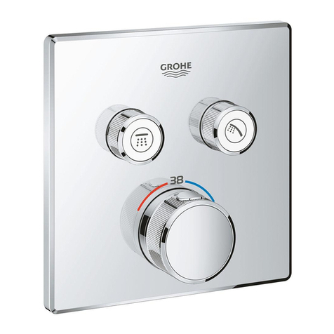
  9. Grohe Talia 19 685 User manual

Grohe Talia 19 685 User manual

página .... 3
English
Français
Español
page....... 1
page....... 2
19 685 (°F) 19 687 (°C)
95.051.131/ÄM 30 197/10.00
Talia
página .... 3
English
Français
Español
page....... 1
page....... 2
950511.book : t95051.fm Seite 1 Freitag, Oktober 6, 2000 12:47 PM
I
C
MOP
N
B
4
C
B
A
C1
1
E
GHJ
B
D
2
L
K
100 °F
(38 °C)
3
5S
B
R
19 687
19 685
S.v.p remettre cette instruction àl'utilisateur de la robinetterie!
Sirvanse pasar ese instrucción al utilizador de la grifería!
Please pass these instructions on to the end user of the fitting!
6
1.
2.
T
L
Kl950511.fm Seite 2 Montag, März 20, 2000 9:08 AM
II
34 900
34 902
19 685 (°F) 19 687 (°C)
Kl950511.fm Seite 3 Montag, März 20, 2000 9:08 AM
1
English
Installation
Trim set installation
- Finish plaster wall and tile up to the fitting template.
When doing so, seal wall openings against water
splashes.
•In the case of tiles laid in mortar, pointing must be
bevelled outwards.
•In the case of prefabricated walls, seal with
elastic sealing compounds.
- Remove fitting template (A), see fig. [1].
Mounting escutcheon, see figs. [1] and [2].
1.Push sleeve (B) with the mark (C) upward onto the
mixer shank, make sure that the marking point (C1)
snaps into the sleeve (B), see fig. [1].
2.Grease seal (D) with the grease provided.
3.Slide the escutcheon (E) over the sleeve (B),
see fig. [2].
4.Slide snap inserts (G) over screws (H) and secure
escutcheon (E) to the valve.
Do not use excessive force to tighten the screws.
5.Cover the srews with cover caps (J).
6.For assembly of the thermostat handle, see chapter
"Adjustment".
If thermostat is installed too deep, the fitting depth can
be increased by 27,5mm (1 1/8") with extension set
Part No. 47 328, see fold-out page II.
Adjustment
Temperature setting, see figs. [3] and [4].
•Before the mixer is put into service, if the mixed water
temperature measured at the point of discharge varies
from the specified temperature set on the thermostat
handle.
•After each service on the thermostat mixer.
1.Open volume control (K) and measure the temperature
of the water emerging with a thermometer, see fig. [3].
2.Turn the green regulator nut (L) clockwise - counter-
clockwise with a screwdriver until the water emerging
has reached a temperature of 100

F (38

C).
3.Fit the thermostat handle (M) so that the 100

F
(38

C) mark on the thermostat handle lines up with the
mark (C) on the sleeve (B), see fig. [4].
4.Insert fixing ring (N).
5.Push on handle (O) and screw on handle cap (P).
Reversed union (hot on right - cold on left).
Replace thermoelement (47 450) or (47 582), see
replacement parts fold-out page II, ref. No.: 47 282 (1/2”)
and 47 379 (3/4”)..
Temperature limitation
When in proper calibration, the temperature range is
limited to 110

F (43

C). There is a safety check
at 100

F (38

C).
If a higher temperature is desired, one can
exceed 100

F (38

C) by overriding the safety check.
Prevention of frost damage
When the domestic water system is drained, the
thermostat mixers must be drained separately, since
check valves are installed in the hot and cold water
connections.
The complete thermostat assembly and check valves
must be unscrewed and removed.
Maintenance
For Maintenance, see fig. [5], [6] and fold-out page II.
I. Thermostat cartridge
1. Turn thermostat handle (47 570, 47 572) to the 100

F
(38

C) safety check, see fold-out page II.
2. Remove handle cap (P) and handle (09 698).
3. Take out fixing ring (N).
4. Pull off thermostat handle (M).
5. Pull sleeve (B) from the mixer shank by pressing
down the tongue (R), see fig. [5].
6. Extract clamp (S).
7. Pull stop ring (T) until resistance is encountered
(approximately 10mm [3/8"]), see fig. [6].
8. Unscrew stop ring (T) complete with regulator nut (L).
9. Remove escutcheon (47 492), see fig. [2] and
installation on page 1, Points 3 - 5, in reverse order.
10. Close both service stops (47 017, 47 467), see fold-
out page II.
11. Unscrew thermostat cartridge (47 450, 47 582) with
24mm (15/16") open-ended wrench.
Reassembly should be carried out in reverse order.
Temperature adjustment is necessary after each service of
the thermostat cartridge (see Adjustment).
II. Check valve
1.Proceed as for maintenance of thermostat cartridge,
points 1 - 4 and 9 - 10.
2.Unscrew check valve (14 116, 47 466) with 17mm
(11/16") socket wrench or 10mm (3/8") allen key.
Reassembly should be carried out in reverse order.
Check, clean and if necessary, replace parts.
Grease with special valve grease (Cat. No. 18 012)
Only original Grohe replacement parts may be used!
Replacement parts, see fold-out page II (* = special
accessories)
Care
Instructions for care of this thermostat mixer will be found
in the Limited Warranty supplement.
950511.book : I95051us.fm Seite 1 Freitag, Oktober 6, 2000 12:47 PM
2
Français
Installation
Installation façade
- Reboucher complètement le mur et le carreler jusqu'au
gabarit d'encastrement en étanchant les ouvertures du
mur pour les protéger contre les éclaboussures.
•En cas de carrelage posédans du mortier, jointoyer
en biseautant vers l'extérieur.
•En cas de murs préfabriqués, étancher avec du
mastic élastique.
- Enlever le gabarit d'encastrement (A), voir fig. [1].
Montage de la rosace, voir les figs. [1] et [2].
1.Pousser le manchon(B) avec la marque (C) vers le haut
dans l'axe du mitgeur thermostatique. Assurez vous que
la marque (C1) s'enclenche dans le manchon (B), voir
fig. [1].
2.Lubrifier les joint (D) avec la graisse àrobinet ci-jointe.
3.Glisser la rosace (E) sur la doille (B), voir fig. [2].
4.Glisser les inserts (G) sur les vis (H) et fixer la
rosace (E) sur le corps.
Ne pas trop serrer les vis.
5.Placer les enjoliveurs (J) sur les vis.
6.Pour le montage de la poignée graduée, veuillez vous
reporter au chapitre "Réglage".
Si le thermostat est encastrétrop profondèment, il est
alors possible d’augmenter la profondeur d’encastrement
de 27,5mm (1 1/8") àl'aide du set de rallonge 47 328, voir
le volet II.
Réglage
Réglage de la température, voir les figs. [3] et [4].
•Avant la mise en service si la température de l'eau
mitigée, mesurée au poste d'utilisation, est différente de
la température de consigne réglée au thermostat.
•Après tout travail de maintenance exécutésur l'élément
thermostatique.
1.Ouvrir le robinet d'arrêt (K) et mesurer la température de
l'eau mitigée àl'aide d'un thermomètre, voir àce sujet la
fig. [3].
2.A l'aide d'un tournevis, tourner l'écrou de réglage
vert (L) vers la droite ou vers la gauche jusqu'àce que
l'eau mitigée ait atteint 38 °C (100 °F).
3.Placer la poignée graduée (M) de telle sorte que le
repère de 38 °C (100 °F) se trouvant sur la poignée
graduée coïncide avec le repère (C) qui est sur l'an-
neau (B), voir fig. [4].
4.Inserez l'anneau de fixation (N).
5.Pousser la poignée (O) et visser le capuchon de la
poignée (P).
Raccordement interverti (eau chaude àdroite - eau
froide àgauche).
Remplacer l'élément thermostatique (47 450) ou
(47 582), voir pièces de rechange volet II,
réf. : 47 282 (1/2”) et 47 379 (3/4”).
Limite de température
Calibrée correctement, la température est limitée à43 °C
(110 °F). La manette est pourvue d'un verrou de securitéà
38 °C (100 °F).
Au cas oùune température supérieure à38 °C (100 °F)
est désirée, il est possible de passer outre le blocage de
sécurité.
Prévention des dommages dûs au gel
Quand le système d'eau domestique est purgé, les
mitigeurs thermostatiques doivent être purgés
séparément, car des clapets de non-retour sont installés
dans les raccords d'eau chaude et d'eau froide.
L'ensemble du thermostatet les clapetsde non-retour doit
être dévisséet déposé.
Maintenance
Maintenance, voir les figs. [5], [6] et le volet II.
I. Elément thermostatique
1. Tourner la poignée graduée (47 570, 47 572) sur la
verrou de sécuritéde 38 °C, voir le volet II.
2. Enlever le capuchon de la poignée (P) et la
poignée (09 698).
3. Enlever la bague de fixation (N).
4. Enlever la poignée graduée (M).
5. Enlevez le manchon (B) de la tige du mélangeur
thermostatique en pressant vous le bas la langu-
ette (R), voir fig. [5].
6. Enlever l'agrafe (S).
7. Tirer sur la bague de butée (T) jusqu'àce que l'on
perçoive une résistance (environ 10mm [3/8"]), voir
fig. [6].
8. Dévisser la bague de butée (T) complètement avec
l'écrou de réglage (L).
9. Démonter la rosace (47 492), voir àce sujet la fig. [2],
et installation page 3 points 3 à5dans le sens inverse
des opérations.
10. Fermer les deux pointeau d'arrêt (47 017, 47 467),
voir le volet II.
11. Dévisser l'élément thermostatique (47 450, 47 582) à
l'aide d'une cléàfourche de 24mm (15/16").
Le montage s'effectue dans l'ordre inverse.
Le réglagede la température est nécessaire après chaque
entretien de l'élément thermostatique, voir Réglage.
II. Clapet de non-retour
1.Même méthode que pour la maintenance de l'élément
thermostatique, points 1 - 4 et 9 - 10.
2.Dévisser le clapet de non-retour (14 116, 47 466) à
l'aide d'une cléàdouille de 17mm (11/16"), voire une clé
mâle coudée pour vis àsix pans creux de 10mm (3/8").
Le montage s'effectue dans l'ordre inverse.
Verifier, nettoyer et le cas échéant, remplacer les pièces.
Graisser avec la graisse àrobinets spéciale (réf. 18 012).
Seules les pièces de rechange d'origine Grohe peuvent
être utilisées.
Pièces de rechange, voir volet II ( * = accessoires
spéciaux).
Entretien
Voir l'annexe concernant la Garantie Limitée pour les
instructions de maintenance de ce mitigeur
thermostatique.
950511.book : I95051f.fm Seite 2 Freitag, Oktober 6, 2000 12:47 PM
This manual suits for next models

1

Other Grohe Bathroom Fixture manuals

Grohe 27 032 User manual

Grohe

Grohe 27 032 User manual

Grohe 27 469 User manual

Grohe

Grohe 27 469 User manual

Grohe 49 113 User manual

Grohe

Grohe 49 113 User manual

Grohe Atrio 20 138 User manual

Grohe

Grohe Atrio 20 138 User manual

Grohe EUROSMART COSMOPOLITAN E 36325001 User manual

Grohe

Grohe EUROSMART COSMOPOLITAN E 36325001 User manual

Grohe TECTRON 38 759 User manual

Grohe

Grohe TECTRON 38 759 User manual

Grohe EUROSMART COSMOPOLITAN E 36 458 User manual

Grohe

Grohe EUROSMART COSMOPOLITAN E 36 458 User manual

Grohe AQUASYMPHONY 26 373 User manual

Grohe

Grohe AQUASYMPHONY 26 373 User manual

Grohe EUPHORIA 26 314 User manual

Grohe

Grohe EUPHORIA 26 314 User manual

Grohe COSTA trend User manual

Grohe

Grohe COSTA trend User manual

Grohe 27 374 User manual

Grohe

Grohe 27 374 User manual

Grohe Chiara 19 206 User manual

Grohe

Grohe Chiara 19 206 User manual

Grohe Tectron 37749 User manual

Grohe

Grohe Tectron 37749 User manual

Grohe Grohtherm F 35 029 User manual

Grohe

Grohe Grohtherm F 35 029 User manual

Grohe EUROSTYLE 33 635 User manual

Grohe

Grohe EUROSTYLE 33 635 User manual

Grohe Allure 19316 User manual

Grohe

Grohe Allure 19316 User manual

Grohe Rainshower 28 368 User manual

Grohe

Grohe Rainshower 28 368 User manual

Grohe GET E 36 366 User manual

Grohe

Grohe GET E 36 366 User manual

Grohe Talia 19 263 User manual

Grohe

Grohe Talia 19 263 User manual

Grohe EUPHORIA SYSTEM 26 240 User manual

Grohe

Grohe EUPHORIA SYSTEM 26 240 User manual

Grohe Essence E 36 252 User manual

Grohe

Grohe Essence E 36 252 User manual

Grohe 27062 User manual

Grohe

Grohe 27062 User manual

Grohe EUROPLUS E 36 207 User manual

Grohe

Grohe EUROPLUS E 36 207 User manual

Grohe Aquatower 3000 User manual

Grohe

Grohe Aquatower 3000 User manual

Popular Bathroom Fixture manuals by other brands

Kohler Mira Sport Max J03G Installation and user guide

Kohler

Kohler Mira Sport Max J03G Installation and user guide

Moen 186117 Series installation guide

Moen

Moen 186117 Series installation guide

Hans Grohe Raindance Showerpipe 27235000 Instructions for use/assembly instructions

Hans Grohe

Hans Grohe Raindance Showerpipe 27235000 Instructions for use/assembly instructions

Signature Hardware ROUND SWIVEL BODY SPRAY 948942 Install

Signature Hardware

Signature Hardware ROUND SWIVEL BODY SPRAY 948942 Install

fine fixtures AC3TH installation manual

fine fixtures

fine fixtures AC3TH installation manual

LIXIL HP50 Series quick start guide

LIXIL

LIXIL HP50 Series quick start guide

KOLO ATOL PLUS installation manual

KOLO

KOLO ATOL PLUS installation manual

Hans Grohe PuraVida 15073000 Instructions for use/assembly instructions

Hans Grohe

Hans Grohe PuraVida 15073000 Instructions for use/assembly instructions

Toto TS111B8 Installation and owner's manual

Toto

Toto TS111B8 Installation and owner's manual

Kohler K-1158-H2 Homeowner's guide

Kohler

Kohler K-1158-H2 Homeowner's guide

Coram Showers OFFSET QUADRANT manual

Coram Showers

Coram Showers OFFSET QUADRANT manual

baliv DU-2010 manual

baliv

baliv DU-2010 manual

odass OD-1710 instruction manual

odass

odass OD-1710 instruction manual

Oxygenics Evolution Easy installation instructions

Oxygenics

Oxygenics Evolution Easy installation instructions

Bradley Express SS Series installation instructions

Bradley

Bradley Express SS Series installation instructions

Helvex TH-974 installation guide

Helvex

Helvex TH-974 installation guide

DURAVIT C.1 C15240 0090 Instructions for mounting and use

DURAVIT

DURAVIT C.1 C15240 0090 Instructions for mounting and use

Sunshower PURE SOLO manual

Sunshower

Sunshower PURE SOLO manual

manuals.online logo
manuals.online logoBrands
  • About & Mission
  • Contact us
  • Privacy Policy
  • Terms and Conditions

Copyright 2025 Manuals.Online. All Rights Reserved.