8
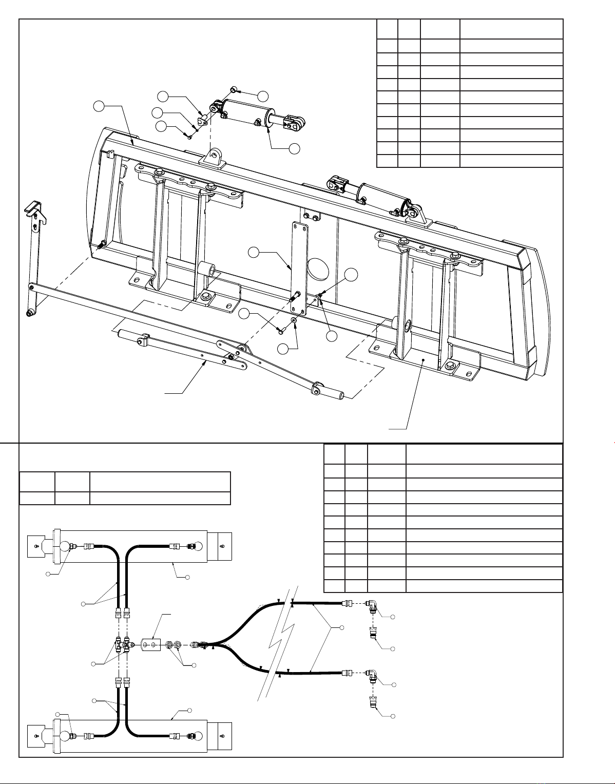
Assembling Lift Components
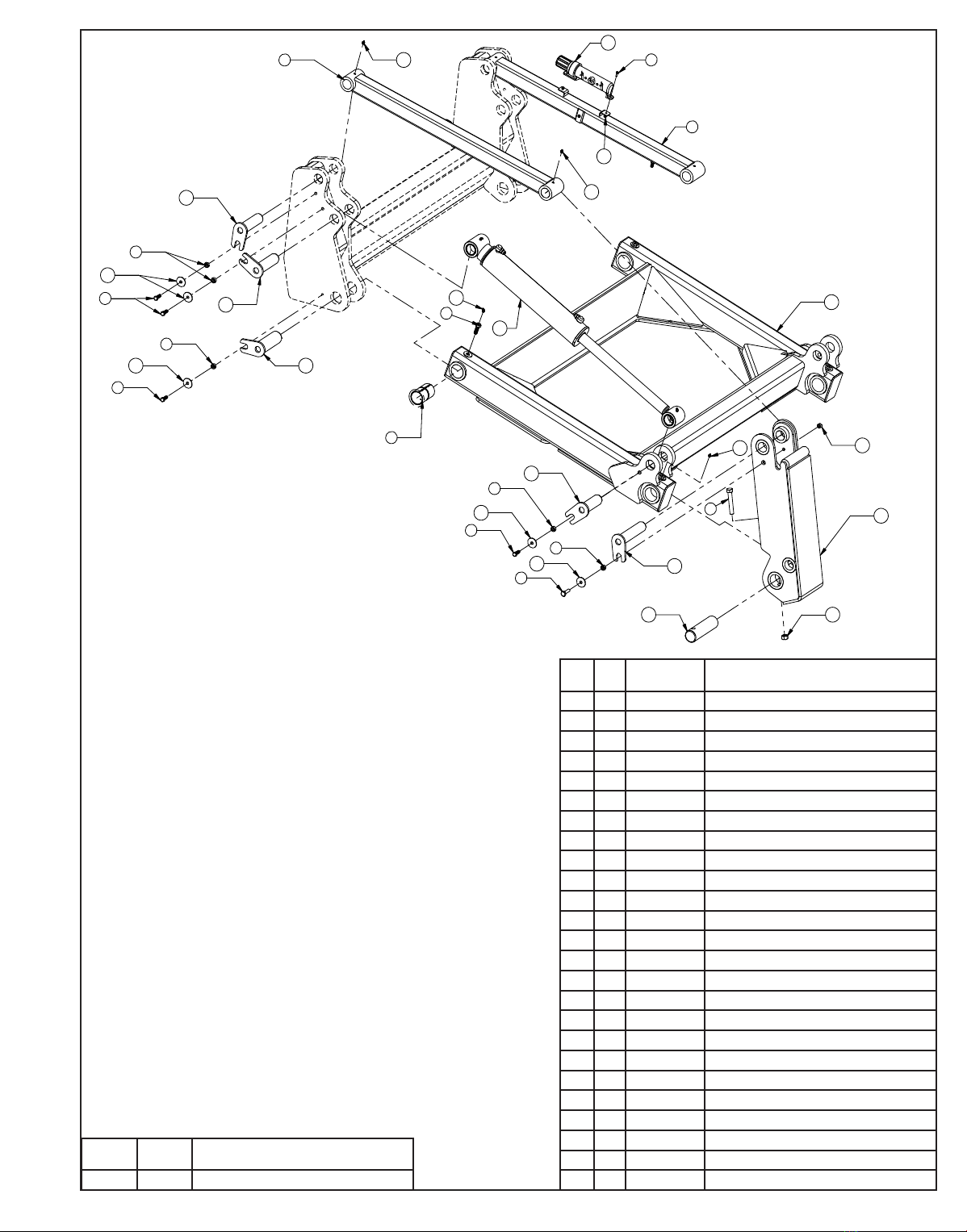
Install undercarriage per the tractor specic mounting instructions. Some assembly of Lift system components
is necessary. Follow the steps listed below. Refer to Page 9 for the correct hardware and orientation of parts.
Remove all pins on each side of the undercarriage.
Position the lift frame between the two plates on both sides of the undercarriage.
Align the lift frame to the bottom holes of the undercarriage and attach with the proper pins and hardware.
Lift the end of the cylinders up and attach to the undercarriage with the proper pins and hardware.
Attach the top arms to the top of the undercarriage with the proper pins and hardware.
Remove the male quick attaches that are in the female quicks on the blade, angle frame, or tilt frame.
Attach the male quick attaches to the lift frame and top arms with the proper pins and hardware.
Install lift cylinders and attach hoses to the cylinders. Refer to Page 10 for lift system hydraulics.
Attach the coupler mounting bracket to each top arm for Angle and Tilt connections. See pages 16-19 for
correct hardware.
Take the long hoses and attach each one to their designated tting from the coupler mount on the top arms
and also attach some to the bulkhead tee tting at the center of the undercarriage for lift. See pages 10, and
16-19 for the correct hose lengths.
Continue to route the hoses thru the tractor. Keep away from all moving parts.
Note: Installer is responsible to route hoses in a practical manner. The hoses need to be routed away
from sharp corners and moving parts and need to be secure.
If applicable, attach the wire harness to the left top arm. Hold in place with a zip tie. Run the other end of the
wire harness up into the cab of the tractor.
Locate the fused power supply. Connect the red wire to power and the black to ground. Install provided switch
into an open switch hole in the right overhead console or another convenient place in the tractor. Connect the
wire harness to the switch.
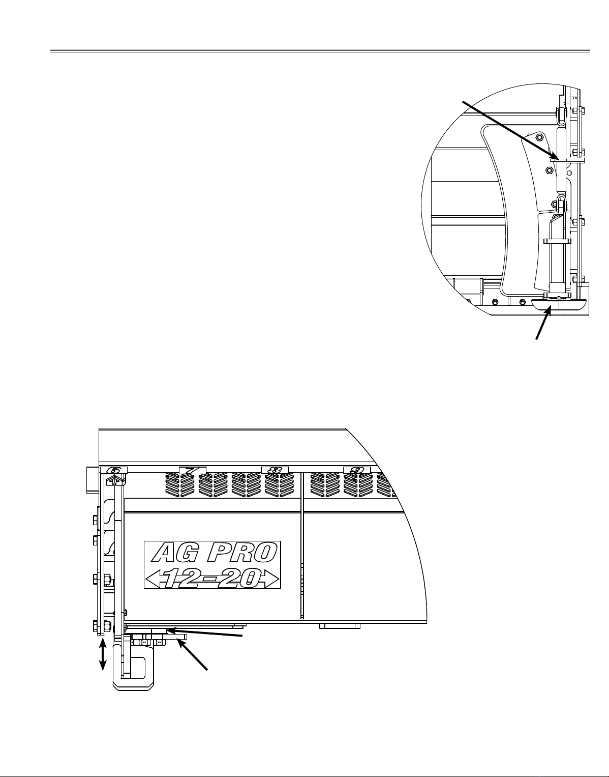
Pull the pin puller handle on the left side of the quick attach system towards the outside of the blade to open
the quick attach system. Refer to Page #12-13 for further clarication on the quick attach system.
Drive the tractor forward slowly until the top edge of the male quick attach is under the top lip of the female
quick attach already on the blade assembly.
Lift the male quick up till the blade is off the ground and the female quick attaches are against the front of the
male quick attaches.
Shut off machine and set the parking brake.
Move the pin puller handle on the left side of the blade assembly towards the center of the blade to lock the
blade in place and use the latch to the lock the handle in place. If applicable, turn up the blade stands on the
blade.
Plug the male couplers into the female couplers on the top arms. If applicable, plug the male blade break away
end of the wire harness into the female blade break away end of the wire harness on the top arm.
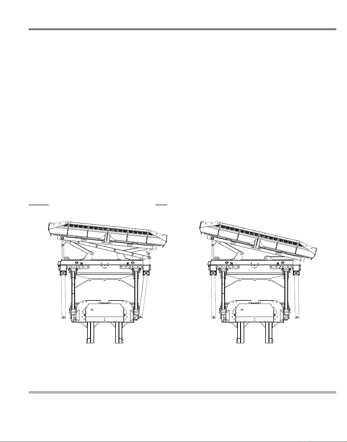
Initial System Startup
Start the tractor and run the blade thru all the functions. If any function does not work properly, bleeding of the
system may be required. If problem still persists, call Grouser Products.
1.
2.
3.
4.
5.
6.
7.
8.
9.
10.
11.
12.
13.
14.
15.
16.
17.
18.
19.