Halls SILVERLINE 86 LEAN TO User manual

SILVERLINE LEAN -TO
86, 106,
126
86Lean-To
126Lean-To
Please refer to website for the most up to date instructions.
www.hallsgreenhouses.com
04/03/20

Introduction
You now own a greenhouse that is believed to be amongst the best in value on the market, and by carefully
following these assembly instructions, it will give you years of trouble-free use. We hope you will find the following
hints and explanations useful.
Your greenhouse is made of aluminium because it is the best all-round material within the price limits the average
householder can afford. It will not swell, shrink, warp or rust. In service, it should become a dull whitish-grey colour,
sometimes with a slightly rough surface on the outside which forms a self-protecting layer.
If you have the horticultural glass, the small panes are less likely to crack due to movement of the greenhouse, are
easier to transport and cheaper to replace in the event of accidental damage.
The acrylic sheet has been selected for its flexibility to form the curved part of the roof, its weather resistance and
lasting clarity.
We recommend that you give your greenhouse all round protection by including it in your house insurance.
Maintenance
To keep your greenhouse clean, occasionally wash the glass and aluminium frame thoroughly with a mild detergent
solution. For difficult stains, white spirit may be used.
The acrylic may be cleaned using warm soapy water applied with a soft cloth. If this does not remove foreign matter
then paraffin or white spirit may be used. Take care not to use any abrasive material that may scratch the acrylic.
Selecting a Site
Choose a sunny spot for your greenhouse where it will receive a fair amount ofsunlight.
Note that the ridge height of your greenhouse without the base is2350mm.
Tools Required
1 – Screwdriver
1 – Spanner 10mm Across Flats
1 – No. 10 Masonry Bit and Drill
1 – Knife
1 – Spoon
1 – Pair of Pliers
1 – SpiritLevel
Important
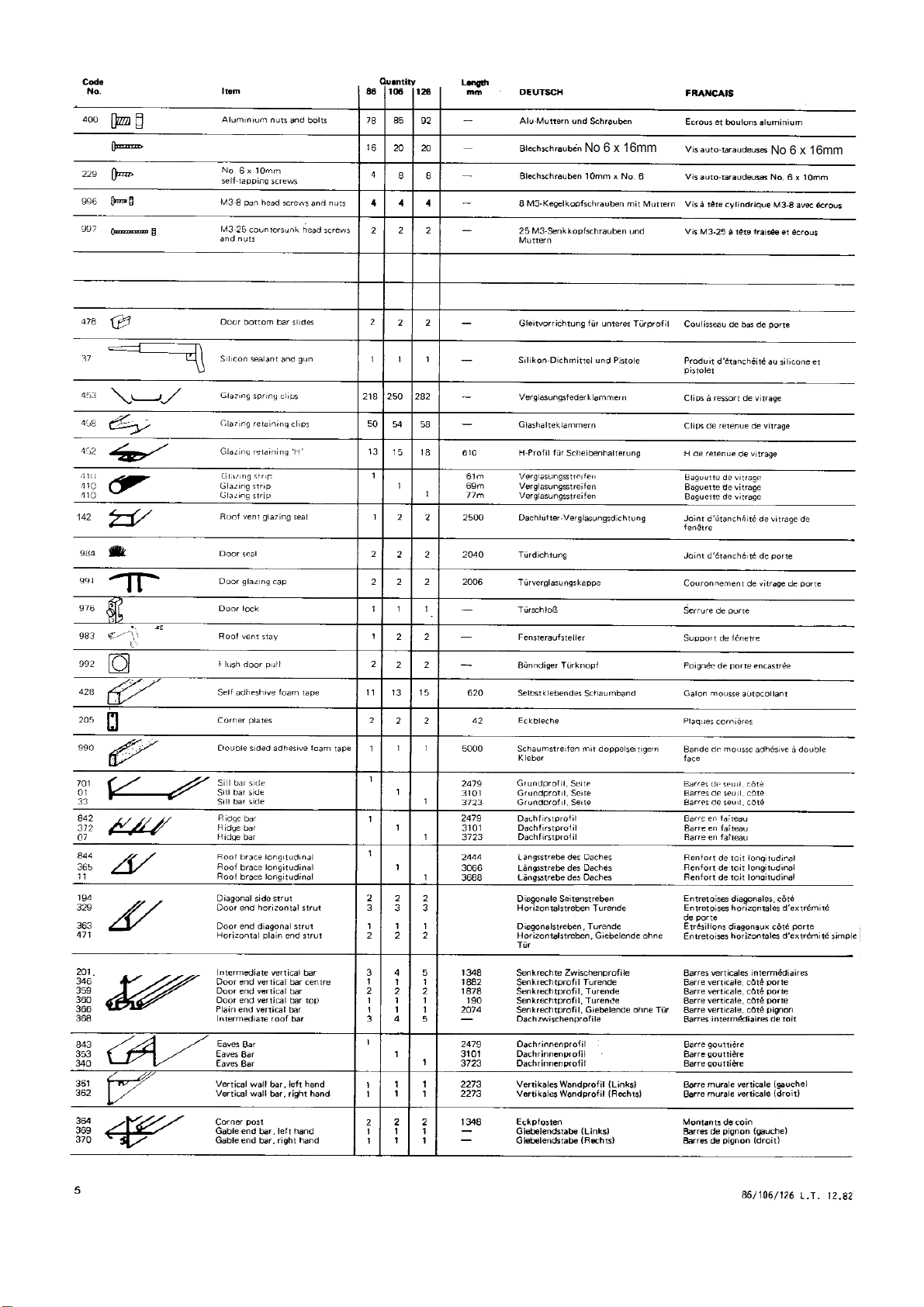
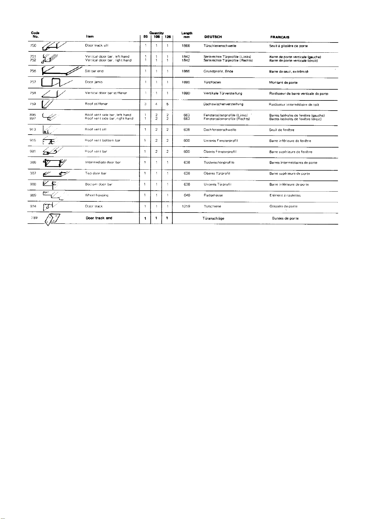
Before starting the assembly of your greenhouse, please check all the contents against the parts list. The parts for
each section are bundled together, so to avoid mixing them up, open each bundle separately. If anything is missing,
please contact Customer Service Dept., using the reply form included in these instructions.
1. Carefully read these instructions before unpacking and do not start to assemble until you fully understand
them.
2. Assistance will be necessary during assembly.
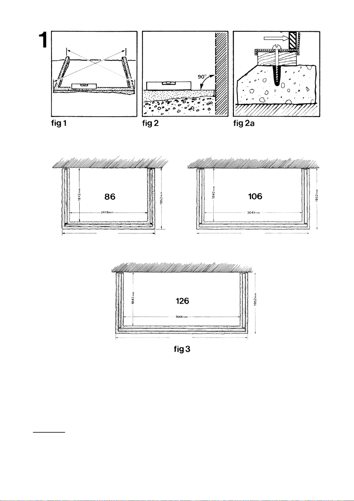
3. Considerable care should be taken in the preparation of a level and square base.
4. Before fixing frame to base, check for squareness and tighten all nuts and bolts. Weatherseal the join
between frame and base, frame and house and all other corner joints.
5. Glazing should not be hurried, but completed in one go, giving great care and attention to sealing the joints
between roof and panes with the sealant provided.
6. To minimise the condensation, werecommend that your greenhouse iswell ventilated. This can beachieved
by the installation ofa louvre vent. A louvre vent can only be fitted in the 106 and the 126 models.
7. It is recommended that a snow guard befitted tothehouse gutter above the greenhouse if there is a risk
of falling debris damaging the greenhouse.
2

1106 No. 6 x 16mm
self- tapping screws
1476
612
1774.5
1839
3

1633
PLEASE NOTE PART 00649 IS A REDUNDANT ITEM THAT IS NO LONGER REQUIRED
4
Silverline Downpipe Kit
x 1
N.B. NUT COVERS ARE ONLY SUPPLIED WITH GREEN COATED
MODELS

Base
You need a base for your greenhouse to ensure that it is level and rigid. To save time and trouble in laying a
traditional brick or concrete base, Halls can supply a simple-to-assemble prefabricated base as an optional extra.
However, if you want to make your own base you should make it to the dimensions in fig. 3. It is most
important that the base is square and level so check that its diagonal measurements are equal as in fig. 1 and
that the angle between the wall and the base is 90ᵒas in fig. 2. Tanalised timber packing of not less than 12mm
thickness and not more than 30mm width should be made to fit the aluminium section, as shown in fig. 2a.
When the greenhouse has been assembled, it can be screwed to the base with no. 12 screws and rawlbolts (not
supplied) through the sill bar (not pre-drilled) in fig. 2a.
IMPORTANT
If you wish to erect your greenhouse on a solid concrete plinth, you should follow the outside dimensions in fig.
3. However it is important to avoid any possibility of water seeping under the base forming puddles. You should
ensure that the base slopes down towards the outside of the greenhouse. The timber packing will have to be
suitably tapered.
N.B. These diagrams are only if you are building your own base as opposed to buying the
prefabricated optional base, which is the easiest option.
GLASS
2635mm
3880mm
3257mm
5

PLEASE NOTE THE
GREENHOUSE MAY BE
SUPPLIED WITH EITHER
SQUARE NUTS OR
HEXAGONAL NUTS.
ABC
ED
6

2. Sides
Laythe parts coded in fig. 4 on the ground. All the illustrations in this section are viewed
from the inside. Join the sill bar(701/01/33)to theeaves bar (843/353/340)with the
intermediate vertical bars (201) – see details Band E.
IMPORTANT
Remember to slide one bolt into the groove of each intermediate vertical bar that is
crossed by a diagonal brace, in order to fix the centre of that brace, as in A.
The parts should be bolted with the square headed aluminium bolts and nuts provided, but
none of the bolts should be fully tightened until the greenhouse is completely assembled.
Bolt the two diagonal struts (194) over the top, as in A, Cand D.
Repeat with the other side.
7

MJH
GIKN
F
L
F
8

3. Plain Gable End
Note that the illustrations and photos are viewed from the inside. Left and right hand are
decided by standing outside the greenhouse.
The door can go on either end. Choose on which end the door should be, and this will
determine whether you build the left orright plain gable end.
Lay out the coded parts asbefore. Attach the corner plate (205) to the gable end bar (369
or 370) and the corner post (364)asin F.
Note that the plain side ofthe corner post should face inside the greenhouse and the bolt
head on the outside.
Bolt the end sill bar(756) to the corner post (364)asin G.Fix the plain end vertical glazing
bars (359 or 366)tothe gable barasinHand slide two bolts for the horizontal strut into
each vertical barbefore fixing the other ends tothe sill barasin I.
Attach the vertical wall bar (361 or 362) to the gable barand the sill asin Jand K.Bolt
the horizontal bars(471) to the bolt in the corner post and the loose bolts in the vertical
bars (359 or 366) as in Fand Mand bolt tothe vertical wall barN.
9

T
UR
O
S
QP
10
1 x Extra
bolt
3 x Extra
bolts
1 x Extra
bolt
3 x Extra
bolts

4. Door Gable End
Lay out the coded parts asbefore and bolt them together loosely using short bolts (400) in
the same order asthe plain gable end, except that the door track (974) should be fitted
BEFORE the vertical bar(346) as inT, Sand U.
Slide 2 bolts into (346)to attach thehorizontal (329)and vertical stiffener (758) as in O.
Match holes instiffener (758) with holes invertical wall bar (346) sothat the stiffener is
the correct way up.
Slide 4 bolts into vertical bar (359) to attach horizontal bar(329) and later the door
jamb (757).
The door lock, if required, can only be fitted on the INSIDE of the greenhouse.
Note that the diagonal strut (363)isfixed tothe sill bar (750) with the same bolt asthe
vertical bars as in Pand fix the other end as in Q.
Loosely fit a nut and bolt into the middle of the door track and then slide small vertical bar
(360)over the bolt head and tighten asinS.
Fix the other endofthe vertical bar to the gable end inthesame way asin R.
11

Plumbline
Spirit Level
Tanalised timber batten
VY
AA BB
Z
W
CC
12

5. Assembly
Note that all the photos and illustrations in this section are viewed from the inside, except fig. 7.
Join the two ends to the side section as in Zand AA. If you find that the corner plates are too rigid, slacken off
the bolts to allow more movement.
Mount the ridge bar (842 or 372 or 07) under the gable bars as in V. Fix ends of roof brace (844 or 365or 11) to
gable ends as in Y. Attach the curved intermediate roof bars (368) as in W. Note that picture Walso has the
roof stiffener attached.
The roof vent sills can only be positioned between two curved intermediate roof bars and should be fixed
loosely into place as in X. To slide the sill bars into place, first insert a bolt at either end of the sills with the bolt
heads uppermost. Then slide roof vent sill (913) very carefully into position from the bottom of the
intermediate roof bars, inserting the two bolts at either end of the sill into the grooves of the bars. Ease into
position detail X.
Before securing the intermediate roof bars (368) slide up THREE BOLTS in each to fit roof brace (844 or 365 or
11), roof stiffener (759) and to attach the bottom of (368) intermediate roof bars to the gutter.
Then use the bottom bolt in each intermediate glazing bar (368) to attach to the gutter. Then use the next
spare bolt to secure roof brace (844 or 365 or 11).
Now fit stiffeners (759) picking up spare bolts in intermediate roof bars, roof braces (844 or 365 or 11) as in CC
and roof vent sill, fixing the top to the bolt in the intermediate glazing bar (368).
Lift the frame onto the prepared base. Drop a plumbline from the top of the greenhouse to make sure that the
ends are perfectly vertical and parallel to the plumbline.
Lightly secure it with a masonry pin (not supplied) driven halfway through one of the securing holes at the top.
Mark the other fifteen or sixteen or seventeen (depending on size of greenhouse) securing holes on the wall
and remove the frame and the masonry pin.
Drill the holes with a no. 10 bit, and plug with no. 10 wall plugs.
At this stage, a 12mm deep bead of mastic (not supplied) should be thoroughly applied between base and sill.
Replace the frame onto the base.
At this stage a 19mm x 16mm tanalised timber batten (not supplied) should be fitted between greenhouse and
wall fig. 7.
Carefully drill securing holes through the timber batten and screw frame to wall. See detail in fig. 7.
Finally, secure the frame to the base. Ifyou have a prefabricated base (which can be bought as an optional
extra), follow the instructions that came with the base. Iffor anyreason they are missing, you can find them on
our website www.hallsgreenhouses.com on the Help andAdvice tab where it says “Base Instructions”.
If you have made your own base, you will need to drill through thesill of the greenhouse as in Section 1,fig. 2a.
Aperfect seal between the timber batten andwall may be obtained byusing a mastic or foam sealing tape(not
supplied).
IMPORTANT
Before finally tightening up all bolts, it is recommended that the sill, eaves, ridge and corner joints are sealed
using the silicon sealant (37) supplied.
This is achieved by releasing one joint at a time to ensure the silicon sealant penetrates each joint.
Finally, go round and tighten all nuts and bolts, but be careful not to tighten so firmly that you break the
threads on the bolts.
13

Spoon
Door Bottom Bar Slider 478
Bottom Horizontal Door Bar
N.B. Build the door before glazing.
DD
EE
FF
GG
VIEWED FROM INSIDE
HH
EXTERNAL
VIEW
INTERNAL
VIEW
GLASS
14
1106
98
9
98
7
OUTSIDE

6a. Door
Lay the parts coded infig. 8 on the ground and attach the vertical door bars
(751 and 752) to the top door bar (987)using the No. 6x 16mm self-tapping
screws (1106)provided as in FF. It is much easier to use an electric drill for
this, making sure the torque setting is correct, i.e. the lowest setting.
Make sure the holes between the bottom door barand the intermediate
bar are further apart than the top in order to fit the shorter top glass pane
B.This can be seen bylaying the two vertical door bars side by side to
match the holes.
Before fitting the intermediate door bar (986) check which side the door pull
should be on, depending on whether your door is on the left side or right side
of the greenhouse. For instance, if your door is on the right, the door pull
should be on the left.
Fit the intermediate door bar (986)and the bottom door bar (988)asin GG and
HH.
Fit the wheel-housing (989)to the top of the vertical door bars asin DD.
Fit the door bottom bar sliders (478)making sure the ears clip over the door
bar, using a spoon if necessary (to fit fully home) asinfig. 8.
Stick flush door pulls (992)into the holes in both sides ofthe intermediate
door bar asin EE.
15

OUTSIDE
INSIDE
Doorglazing
Remember glass is fragile, handle with care using gloves. Stick double-sided adhesive foam strip (990)toboth vertical door bars
as in II, making sure the aluminium surface is clean anddry.
Place the bottom pane of glass in position, making sure it is absolutely central.
Peeloff the backing tape fromfoam strip upthe vertical door bar only as far as the height of the pane of glass. Making sure glass
is square, push onto foam strip.
Then repeat for the top pane, noting that the top pane is shorter. Wheel housing can beeased uptoallow the glass to fit.
Clip door glazing cap (991)into both vertical door bars as in II.
With the door flat on the ground or on a bench, starting at the bottom, push down fairly hard with the heel of your hand
working your way to the top, virtually flattening the capping (991) it will clip into both vertical door bars as in II.
Cut the top off level with the top of the glass with a hack saw. Then re-fit the door wheel housing. Slide door seal (984)into both
vertical door bars as in II and crimp bottom end ofdoor bars with pliers toprevent seal sliding down.
16
INSID
E
TOUGHENED
GLAZING
610 x
765
610 x 920

OO
BF
RR
PP
INSIDE OUTSIDE
OUTSIDE INSIDE
17

6c. Door Hanging
Slide the door onto the door track, making sure the bottom door bar fits over the sill, as in
NN.
Adjust the bolts on the wheelhousing, so that the weight of the door is taken by the wheels,
but ensuring that the bottom door bar fits over the sill, so that it acts as a guide, and that
the vertical door bars do not catch on the track.
Tighten the bolts so that the door is held firmly and cannot wobble.
Note that the door lock is fitted on the INSIDE of the greenhouse so you may not need it.
Fit door lock (976) to door jamb (757) with the two screws (997) through the holes provided
in the door jamb as in PP.
Fit door jamb (757) to the door end vertical bar (359), noting the 2 small holes in end of the
door jamb are at the top and using the four bolts already in place, line up bolts with slots in
door jamb, push into place and tighten nuts as in QQ and RR.
Align the two holes in end of door track with the two holes on the top of the door jamb and
bolt into place as in OO using screw (996).
Fit door track ends (789) as in BF.
18

TOP
TOP
TOP
TOP
Gasket
Flat wooden
stick
Push
SS
XX
981
VV
Completed vent from inside
Completed vent from outside
YY
WW
19
1106

7. Roof Vent
Remember, glass isFRAGILE!Handle with care using gloves.
Working ona flat surface, cut four pieces of gasket (138) as in fig. 11sothat the edges of
the glass are completely covered bythe gasket. Donot stretch. Cutting thegaskets slightly
oversize will ensure a tight fit at the corners.
Place one length ofgasket onto the bottom edge of theglass, fit vent bottom bar (915).
Place centrally over the glass. Knock down with a wooden,rubber or hide mallet with the
glass held vertical, supporting the free edge on a wooden block asin TT.
Repeat at the opposite glass edge with vent top bar (981)making sure the part is the
correct way up.
Repeat the other twosides, making sure they are the correct way round, noting the hole
nearest the end ofthe roof vent side bar isat the top nearest the ridge.
Apply a small amount ofsilicon sealant toeach corner joint toseal join in gasket.
Assemble the corners ofthe frame by means ofthe four self-tapping screws (1106)asin
XX and YY, straightening the bars ifbowed.
Check the diagonal measurements for squareness. Adjust ifnecessary and tighten the
screws.
Bed gaskets down onto frame on both sides of the glass using a flat wooden stick, as in UU.
Slide the top bar of the roof vent into the mating portion at the end of the ridge bar and
slide along ridge bar into position required as in VV.
If you havedifficulty sliding the roof vent into place, the parts may be lubricated with a little
petroleum jelly orgrease.
Loosely fit the roof vent stay (983) to the approximate middle ofthe roof vent barand the
sill bar (picture SS) using self-tapping screws (229) as in WW.
Adjust roof vent sill barwith vent in closed position.
If the roof vent catches onthe top ofthe glazing bar, the nut holding this barmay
be slackened off and the glazing barmoved slightly.
The nuts holding the roof vent sill (SS) should be left loose for adjustment when fitting
the roof vent.
20
This manual suits for next models
2
Table of contents
Other Halls Greenhouse Kit manuals
Popular Greenhouse Kit manuals by other brands

Rion
Rion Grand Gardener Assembly instructions

Rhino Shelter
Rhino Shelter Round Style Portable Building Assembly instructions

Conviron
Conviron 20 Series installation manual

Juliana
Juliana SUNLINE Assembly instructions

Norfolk Greenhouses
Norfolk Greenhouses BCCPSW1800EXT Assembly instructions

GrowSpan
GrowSpan 105175F manual