Hama 00220824 User manual

00
220824
TV WALL BRACKET
Full motion
GOperating Instructions

Contents
1. Explanation of warning symbols and notes ..........................3
2. Package contents.............................................4
3. Additionally required tools ......................................4
4. Safety instructions ............................................5
5. Application and specifications ...................................5
6. Preparation and assembly ......................................6
6.1 Mounting on the wall.........................................7
6.1.1 Preparing the intended mounting surface ........................7
6.1.2 Attaching the wall bracket....................................8
6.2 Mounting on the TV set .......................................9
6.2.1 VESA variants 75 x 75, 100 x 100, 200 x 200 ....................10
6.2.2 VESA variants 300 x 300, 400 x 400 ...........................10
6.2.3 Mounting the VESA plate on the back of the TV set ................11
6.3 Mounting the TV on the wall bracket ............................12
7. Adjustment & maintenance ....................................13
8. Setting options..............................................13
9. Technical data ..............................................14
10. Warranty disclaimer .........................................15
11. Service and support .........................................15
12. Warranty conditions .........................................15

GOperating Instructions
Thank you for choosing aHama product.
Take your time and read the following instructions and information completely. Please keep these instructions
in a safe place for future reference. If you sell the device, pass on the illustrated quick start guide and the safety
instructions in printed form to the new owner.
1. Explanation of warning symbols and notes
Warning
This symbol is used to indicate safety instructions or to draw your attention to specic hazards and risks.
Note
This symbol is used to indicate additional information or important notes.

2. Package contents
•TV wall bracket
•Wall plate cover (2x)
•Cable manager (1x)
•Extension (4x)
•Mounting kit
•Safety instructions, illustrated quick start guide
Mounting kit
A1 8x60 (x2) D2 M8x20(x4)
A2 Ø10x60 (x2) D3 M8x30(x4)
A3 M8 (x2) D4 M8x50(x4) *
B1 M6 (x4) E1 M4x12 (x4)
B2 Ø8x10 (x4) E2 M4x20(x4)
B3 Ø8x20(x4) F1 M6x12 (x2)
C1 M6x12 (x4) F2 M6 (x2)
C2 M6x20(x4) F3 M6x8 (x8)
D1 M8x12 (x4) F4 (x2)
* M8x50 + Ø 8x5 = M8x45
Note
Please check the mounting kit for completeness before installing the bracket andensure that thereareno
faulty or damaged parts.
3. Additionally required tools
10 mm 13
Note
Never install the bracket alone. Seek assistance and help!

4. Safety instructions
Warning
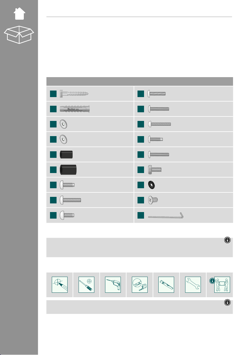
•Given the multitude of terminal devices and wall structures available on the market, the supplied mounting
kit is unable to cover every option.
•It occasionally happens that the screws for attaching the device to the bracket are too long.
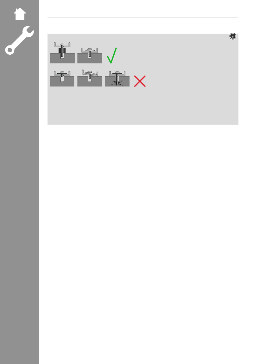
•Please note that the supplied wall plugs are for use with solid, hollow and board construction materials
only.
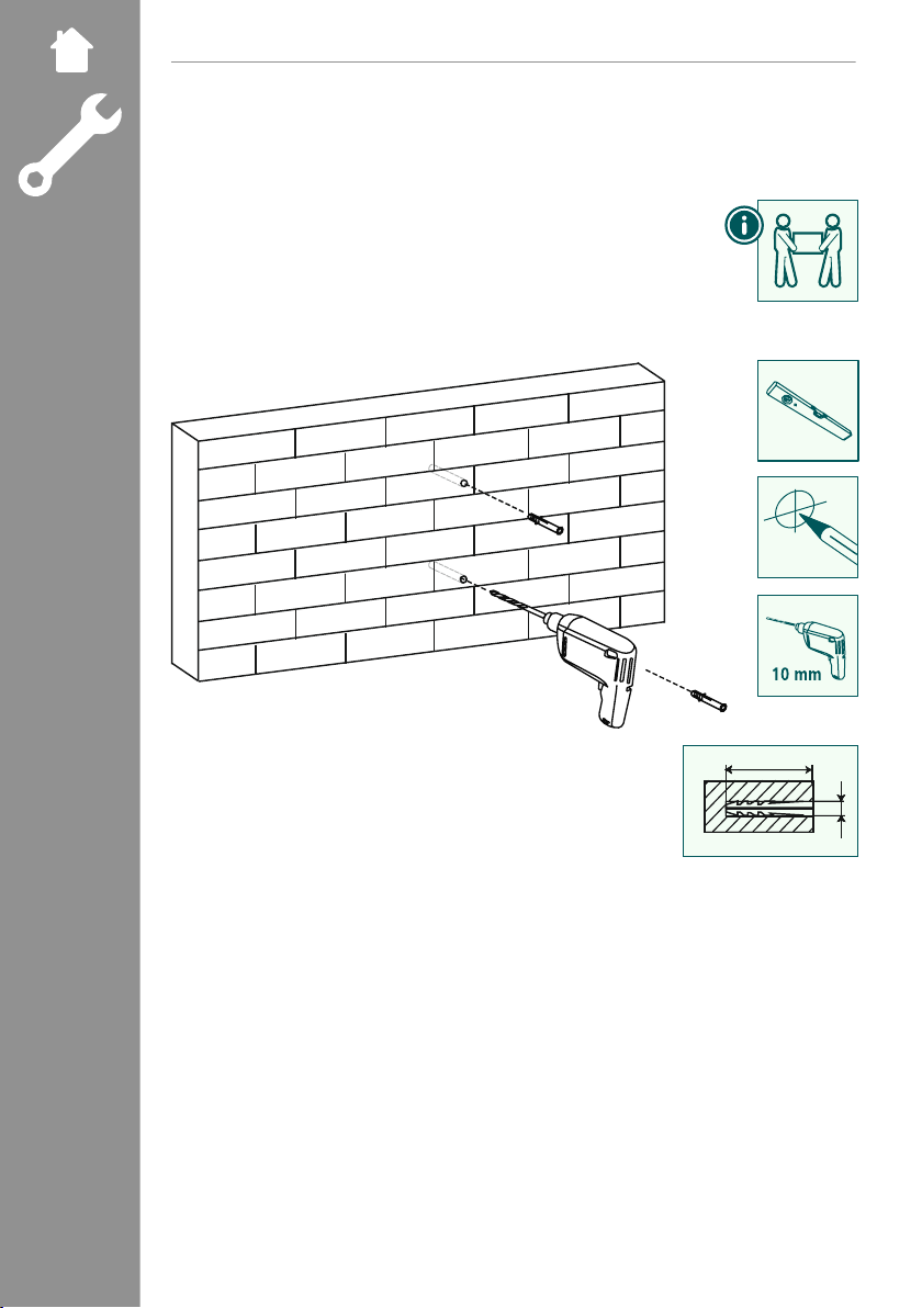
•Read the operating instructions for your terminal device before attempting to mount it. The instructions
provide information about the type and measurements of suitable fastening materials.
•If the supplied mounting kit does not contain suitable fastening materials for mounting the terminal device,
purchase these from a specialised dealer.
•Never apply force during assembly. This can damage your device or the holder.
•If in doubt, have this product installed by aqualied technician - do not attempt to installit yourself!
•Do not mount the product above locations where persons might sitor stand.
•Once you have mounted the product and the attached load, check thatthey aresuciently secureand safe
to use.
•You should repeat this check at regular intervals (at least every three months).
•Ensure that the product does not exceed its maximum permitted carrying capacity and thatno load exceeding
the maximum permitted dimensions is attached.
•Make sure that the product is loaded symmetrically.
•Maintain the necessary safety clearance around the attached load (depending on the model).
•In the event of damage to the product, remove the attached load and stop using the product.
•Do not attach any additional objects to the product.
5. Application and specifications
•The bracket is used for mounting at screens in private, non-commercial households.
•The bracket is intended only for use inside buildings.
•Use the bracket only for the intended purpose.

6. Preparation and assembly
Note
•Never install the bracket alone. Seek assistance and help!
•Different end devices have different connections for cabling and otherdevices. Before commencing the
installation, check whether the necessary connections can stillbe reached aftermounting.
•Depending on the product and mounting method, you may not need allparts of the mounting kit. It is
therefore possible that unneeded screws and other small parts will be left overeven aftercorrect mounting.
Keep these in a safe place together with these operating instructions for use for later reference (sale of the
product, moving house, relocation of the bracket, new TV, etc.).
Warning
•Be aware that the brackets are only suitable for wall mounting.
•Before installation, check that the wall you have chosen is suitable for the weight to be mounted. Also
make sure that there are no electric, water, gas or other lines running through the wall at the mounting
site.
Note - Fischer plugs
The Fischer plugs supplied are approved for the following building materials:
•Concrete
•Plasterboard and gypsum breboard
•Vertical perforated brick
•Lightweight concrete hollow block
•Hollow brick and concrete ceilings
•Perforated sand-lime brick
•Solid sand-lime brick
•Natural stone
•Aerated concrete
•Chipboard
•Solid plaster boards
•Lightweight concrete solid block
•Solid brick

6.1 Mounting on the wall
6.1.1 Preparing the intended mounting surface
Get support and help from other people for the following assemblysteps.
70 mm
Ø10 mm
•First use the bracket as a template and measure if necessary to ensure thatthe position is correct. Use aspirit
level to check the horizontal and vertical alignment of the bracket on the wall.Now mark the holes on the
wall.
•To attach the wall bracket to the wall, you need a drill and a drilling attachment with a diameter of 10mm.
Make sure that the drilling attachment is suitable for the intended wall. The depth of the hole should be
70 mm .
•To ensure a secure hold, vacuum out the drill holes with a vacuum nozzle so that the drill hole is free of drill
dust. Now insert the plug [A2] into the drill hole so that it is ush with the hole.

6.2 Mounting on the TV set
Note
•Given the multitude of terminal devices structures available on the market, we cannot describe all possible
mounting options here.
•Please ensure that the bracket lays at and evenly on the back of the television.
•Use the enclosed spacer to even out any unevenness on the back of the television.
•Ensure that all screws have the proper length and can be mounted until they are hand-tight.

6.2.3 Mounting the VESA plate on the back of the TV set
Curved TV rear
C2, D2, D4, E2 B1 B2
+ +
D3, D4 B3
+
C1,C2,
D1,D2, D3,
D4, E1, E2
B1 B2, B3
M8x50M8x45 (D4)Ø 8x5
+=
Flat TV back rear
C1,D1,D4, E1 B1
+
•Mount the VESA plate on the back of your TV.
•Note the combination of screw, washer and spacer listed above for your ator curved TV.

6.3 Mounting the TV on the wall bracket
Get support and help from other people for the following assembly step.
During installation, the joints must be adjusted so that lateral movement of the TV set is possible.
•Hang the TV with the mounted VESA plate on the wall bracket as shown above.
F1 F2
•Then x the lateral fastening screws [F1] (with the washer [F2]).

7. Adjustment & maintenance
Note
Never adjust the bracket alone. Seek assistance and help!
Note - tiltable / full-motion brackets
•Ensure that no electrical cables are crushed or damaged during installation or adjustment.
•During adjustment, ensure that the product is loaded symmetrically and that the maximum permitted carrying
capacity is not exceeded.
•Check the strength and operational safety of the bracket and the load attached to it at regular intervals (at
least quarterly).
•Clean only with water or conventional household cleaners.
8. Setting options
180°
Swivel
56 -416mm
extendable
-12°/+5°
Tilting
•To adjust the tilt angle, open the fastening screws at the side, set the required tilt and then secure the screw
[F1] in place again.

9. Technical data
Maximum load: 25 kg
Screen diagonal:
81.0 - 165.0 cm (US: 32" - 65")
Depth: 5.6 cm - 41.6 cm
Tilt: -12°/+5° (depending on device)
Swivel range: Up to 180° (depending on device) at 3 joints
Dimensions of the wall mounting plate: 6.0 x 25.3 cm
Mount:
Compliant with VESA standard:
75 x 75
100 x 100
200 x 200
300 x 300
400 x 400

10. Warranty disclaimer
Hama GmbH & Co KG assumes no liability and provides no warranty for damage resulting from improper
installation/mounting, improper use of the product or from failure to observe the operating instructions and/or
safety notes.
11. Service and support
Please contact Hama Product Consulting if you have any questions about this product.
Hotline: +49 9091 502-0 (German/English)
Further support information canbe found here: www.hama.com
12. Warranty conditions
For this product, HAMA GmbH&CoKG grants you an extended manufacturer's warranty for freedom from
defects, usability, workmanship and the durability of the materials used foraperiod of 10 years. Excluded from
the guarantee is the compatibility of the product with future standards of further developed hardware.
Within the specied period, Hama GmbH&CoKG will remedy a justied warranty claim at its own discretion,
free of charge, either by repair or replacement.
The warranty period begins on the date of purchase of this product and is valid throughout the EU.
The warranty granted is in addition to and does not affect your statutoryrights. Damage caused by improper
use, normal wear and tear, exposure to chemicals or force majeure, as well as tampering or repairs by you or
third parties, are excluded from the warranty.
Furthermore, accessories that are not part of the basic equipment of the product (promotional parts) are
excluded from the warranty.
In the event of a warranty claim, please contact us at Hama GmbH & Co KG, Dresdner Str. 9, 86653 Monheim,
Germany, enclosing proof of purchase. Youare also welcome to contact us at www.hama.de or by phone on
+49 (0)9091/502-0.
Table of contents
Other Hama TV Mount manuals