Inficon MAG050 User manual

Cold Cathode Gauge
MAG050
MAG060
Operating Manual
Incl. EU Declaration of Conformity
tinb43e1 (2018-06)
Product Identification
In all communications with INFICON, please specify the
information on the product nameplate. For convenient
reference copy that information into the space provided
below.
Validity
This document applies to products with part number
399-840 (MAG050, DN 25 ISO-KF)
399-841 (MAG050, DN 40 ISO-KF)
399-842 (MAG050, DN 40 CF-F)
399-845 (MAG060, DN 40 ISO-KF)
399-846 (MAG060, DN 40 CF-F)
The part number (PN) can be taken from the product name-
plate.
If not indicated otherwise in the legends, the illustrations in
this document correspond to the product with vacuum
connection DN 40 ISO-KF. They apply to the products with
other vacuum connections by analogy.
Intended Use
The above Cold Cathode Gauges have been designed for
vacuum measurement in the pressure range of
MAG050: 2×10⁻⁹ ... 5×10⁻³ hPa│mbar
MAG060: 1×10⁻¹⁰ ... 5×10⁻³ hPa│mbar.
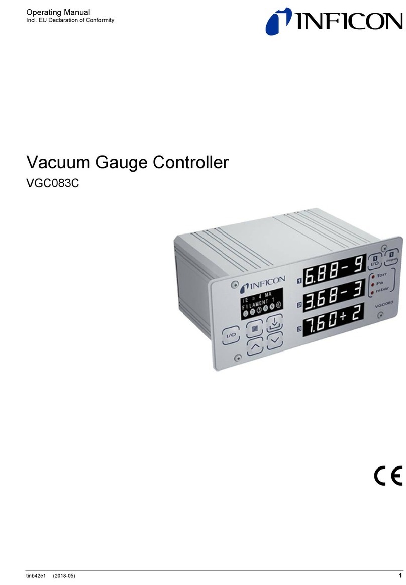
They are used together with a INFICON measurement and
control unit of the type VGC083C.
Functional Principle
Over the whole measurement range, the measuring signal is
output as logarithm of the pressure.
The MAG050 / MAG060 function with a cold cathode ioniza-
tion measurement circuit (according to the inverted magne-
tron principle).
Safety
Symbols Used
Information on preventing any kind of physical injury.
Information on preventing extensive equipment and envi-
ronmental damage.
Information on correct handling or use. Disregard can lead
to malfunctions or minor equipment damage.
Note
Personnel Qualification
All work described in this document may only be carried
out by persons who have suitable technical training and the
necessary experience or who have been instructed by the
end-user of the product.
General Safety Instructions
•Adhere to the applicable regulations and take the neces-
sary precautions for the process media used.
•Consider possible reactions between the materials
(→Technical Data) and the process media.
•Consider possible reactions (e.g. explosion) of the pro-
cess media due to the heat generated by the product.
•Adhere to the applicable regulations and take the neces-
sary precautions for all work you are going to do and con-
sider the safety instructions in this document.
•Before beginning to work, find out whether any vacuum
components are contaminated. Adhere to the relevant
regulations and take the necessary precautions when
handling contaminated parts.
DANGER
DANGER: magnetic fields
Strong magnetic fields can disturb electronic
devices like heart pacemakers or impair their
function.
Maintain a safety distance of ≥10 cm between
the magnet and the heart pacemaker or prevent
the influence of strong magnetic fields by anti-
magnetic shielding.
Communicate the safety instructions to all other users.
Responsibility and Warranty
INFICON assumes no liability and the warranty becomes null
and void if the end-user or third parties
•disregard the information in this document
•use the product in a non-conforming manner
•make any kind of interventions (modifications, alterations,
etc.) on the product
•use the product with accessories not listed in the corre-
sponding product documentation.
The end-user assumes the responsibility in conjunction with
the process media used.
Gauge failures due to contamination are not covered by the
warranty.
Technical Data
Admissible temperatures
Storage
–40 °C … +80 °C
Operation
MAG050
+5 °C … +80 °C
(with normal cable)
+5 °C … +150 °C
(with high temperature cable)
MAG060 +5 °C … +80 °C
(with normal cable)
+5 °C … +250 °C
(with high temperature cable)
Bakeout
MAG050
+150 °C (without cable)
MAG060 +250 °C (without cable)
Relative humidity max. 80% at temperatures
up to +31 °C, decreasing to
50% at +40 °C
Use indoors only
altitude up to 2000 m NN
Measurement range (air, N2)
MAG050
2×10
-9
… 5×10
-3
hPa│mbar
MAG060 1×10⁻¹⁰ … 5×10⁻³ hPa│mbar
Accuracy (N2, typical)
30% of reading
Repeatability (typical) 5% of reading
Gas type dependence →Appendix
Protection type
IP 40
Overpressure ≤900 kPa (≤9 bar)
for inert gases and tempera-
tures <55 °C only
Radiation resistance
MAG050
–
MAG060
10
9
rad
Operating voltage
(in measuring chamber)
≤3.3 kV
Operating current
(in measuring chamber)
≤700 µA
Electrical connection
Connector
Type
SHV
coaxial cable
Cable length between gauge
and measurement unit
MAG050
max. 100 m
(40 m if the lower limit of the
measurement range is used
→[1], Operating Manual
VGC083C)
MAG060 max. 100 m
(6 m if the lower limit of the
measurement range is used,
→[1], Operating Manual
VGC083C)
Materials on the
vacuum side
Vacuum connection
Measuring chamber
DN 25 ISO-KF
DN 40 ISO-KF / CF-F
Feedthrough isolation
Internal seal MAG050
MAG060
Anode
Ignition aid
stainless steel (1.4306)
stainless steel (1.4104)
stainless steel (1.4306)
ceramic (Al2O3)
FPM
Ag
Mo
stainless steel (1.4310)
Internal volume ≈20 cm³
Dimensions [mm]
Weight 600 g (DN 25 ISO-KF, DN 40 ISO-KF)
850 g (DN 40 CF-F)
Installation
Vacuum Connection
DANGER
Overpressure in the vacuum system >100 kPa
(>1 bar)
Injury caused by released parts and harm
caused by escaping process gases can result if
clamps are opened while the vacuum system is
pressurized.
Do not open any clamps while the vacuum sys-
tem is pressurized. Use the type clamps which
are suited to overpressure.
DANGER
Overpressure in the vacuum system >250 kPa
(>2.5 bar)
KF connections with elastomer seals (e.g.
O-rings) cannot withstand such pressures. Pro-
cess media can thus leak and possibly damage
your health.
Use O-rings provided with an outer centering
ring.
DANGER
Protective ground
Incorrectly grounded products can be extremely
hazardous in the event of a fault.
The gauge must be electrically connected to the
grounded vacuum chamber. This connection
must conform to the requirements of a protective
connection according to EN 61010:
•CF connections fulfill this requirement
•For gauges with a KF flange, use a conduc-
tive metallic clamping ring
Caution
Vacuum component
Dirt and damages impair the function of the
vacuum component.
When handling vacuum components, take ap-
propriate measures to ensure cleanliness and
prevent damages.
Caution
Dirt sensitive area
Touching the product or parts thereof with bare
hands increases the desorption rate.
Always wear clean, lint-free gloves and use
clean tools when working in this area.
When CF vacuum connections are made, it can be advanta-
geous to temporarily remove the magnet unit (→Removing
the Magnet Unit).
Mount the gauge so that no vibrations occur. Vibrations at
the gauge cause a deviation of the measured values.
The gauge may be mounted in any orientation.
To keep condensates and particles from getting into
the measuring chamber preferably choose a hori-
zontal to upright position.
Remove the protective lid and connect the product to the
vacuum system.
Keep the protective lid.
Removing the Magnet Unit
(CF vacuum connection only)
For reasons of tolerance, the same magnet unit has
to be used again when reassembling the gauge.
Tools Required
•Allen wrench AF 1.5
•Open-end wrench AF 7
Procedure
Unfasten the hex head screw (3) on the magnet unit (4)
and remove the magnet unit.
The magnetic force and the tendency to tilt
make it more difficult to separate the magnet
unit and the measuring chamber (7).
Make the vacuum connection between the gauge and
the vacuum system.
Mount the magnet unit and lock it with the hex head
screw (3).
Electrical Connection
•Make sure the vacuum connection is properly
made.
•The VGC083C control unit must be turned off
before any work is performed on the gauge or
sensor cable.
Connect the sensor cable to the gauge and to the INFICON
measurement unit.
Operation
The gauge is ready for operation as soon as it has been
connected.
Gas type Dependence
The measuring signal depends on the type of gas being
measured. The value displayed is accurate for dry air, N2, O2
and CO. It can be mathematically converted for other gases.
This can be done by entering the corresponding calibration
factor on the INFICON measurement unit (→Appendix).
Ignition Delay
When cold cathode measurement systems are activated, an
ignition delay occurs. The delay time increases at low pres-
sures and for clean, degassed gauges it is typically:
1×10⁻⁷ hPa│mbar ≈0.1 minute
1×10⁻⁸ hPa│mbar ≈1 minute
1×10⁻⁹ hPa│mbar ≈5 minutes
1×10⁻¹⁰ hPa│mbar ≈20 minutes (MAG060 only)
The ignition is a statistical process. Already a small amount
of depositions on the inner surfaces can have a strong in-
fluence on it.
Contamination
Gauge failures due to contamination are not covered by the
warranty.
Cold cathode gauges are subject to contamination. The de-
gree of contamination and subsequently the accuracy of the
measured value depend on:
•the pressure in the vacuum chamber
•contaminants inside the vacuum chamber (vapors, pro-
cess particles, etc.)
•the measurement current.
To avoid extensive contamination switch the gauge
on only at pressures of <10-2 hPa│mbar.
Contamination generally has the effect that the pressure indi-
cation is too low. If the contamination is severe, instability
occurs. Contamination layers can peel off in the measuring
chamber and cause short circuits.
Depending on the operating conditions, cleaning may there-
fore be necessary after a few days or after a few years.
Deinstallation
Contaminated parts
Contaminated parts can be detrimental to health
and environment.
Before beginning to work, find out whether any
parts are contaminated. Adhere to the relevant
regulations and take the necessary precautions
when handling contaminated parts.
Caution
Vacuum component
Dirt and damages impair the function of the
vacuum component.
When handling vacuum components, take ap-
propriate measures to ensure cleanliness and
prevent damages.
Caution
Dirt sensitive area
Touching the product or parts thereof with bare
hands increases the desorption rate.
Always wear clean, lint-free gloves and use
clean tools when working in this area.
Procedure
Turn off the VGC083C control unit.
Vent the vacuum system and disconnect the sensor
cable from the gauge.
Remove gauge from the vacuum system and install the
protective lid.
Maintenance
Sensor failures due to contamination are not covered by the
warranty.
Cleaning the Gauge / Changing Parts
Contaminated parts
Contaminated parts can be detrimental to health
and environment.
Before beginning to work, find out whether any
parts are contaminated. Adhere to the relevant
regulations and take the necessary precautions
when handling contaminated parts.
Model:
PN:
SN:
INFICON AG, LI-9496 Balzers
ø63.5
92
97.5
DN 40 CF-F
DN 25 ISO-KF
DN 40 ISO-KF
AF 7
Vacuum
chamber
4
3
7
Original: English
t i nb43e1

Caution
Vacuum component
Dirt and damages impair the function of the
vacuum component.
When handling vacuum components, take ap-
propriate measures to ensure cleanliness and
prevent damages.
Caution
Dirt sensitive area
Touching the product or parts thereof with bare
hands increases the desorption rate.
Always wear clean, lint-free gloves and use
clean tools when working in this area.
Precondition
•Gauge removed from vacuum system
Tools required
•Allen wrench AF 3
•Open-end wrench AF 7
•Pliers for circlip
•Polishing cloth (grain 400) or Scotch-Brite
•Tweezers
•Mounting tool for ignition aid
•Cleaning alcohol
Disassembling the Gauge
(MAG050 →Figure 1, MAG060 →Figure 2)
Precondition
•Gauge removed from vacuum system
Procedure
Unfasten the hex head screw (3) on the magnet unit (4)
and remove the magnet unit.
The magnetic force and the tendency to tilt
make it more difficult to separate the magnet
unit and the measuring chamber (7).
For reasons of tolerance, the same magnet
unit has to be used again when reassembling
the gauge.
Remove the circlip (5) and the pole insert (6) from the
measuring chamber (7).
Loosen the 2 hex socket screws (1a) and remove the
coaxial connector (2a).
Remove the 4 (or 2) hex socket screws (8) incl. the
lock washers (8a) on the back of the measuring cham-
ber (7).
MAG050: Carefully remove the following items in this
order: pressure piece (9), complete anode (10), inner
ring (11) and FPM seal (12).
MAG060: Carefully remove the following items in this
order: pressure piece (9), washer (10b), complete
anode (10), metal seal (11) and centering ring (12).
The parts can now be cleaned or replaced individually
(→next section).
Cleaning the Gauge
Procedure
DANGER
Adhere to the relevant regulations and take the necessary
precautions when handling and disposing of cleaning
agents.
Cleaning the measuring chamber and the pole insert:
Clean the inside walls of the measuring chamber and
the pole insert to a bright finish. Use a polishing cloth.
Caution
Sealing surfaces must only be worked concentrically.
Rinse the measuring chamber and the pole insert with
alcohol.
Dry both.
Cleaning or replacing the anode (10):
Remove the old ignition aid (10a), for example with
tweezers.
Rub the anode pin to a bright finish by means of a
polishing cloth.
Caution
Do not bend the anode.
Do not carry out mechanical work on the ceramic
part.
Rinse the anode with cleaning alcohol.
Dry the anode.
Insert the new ignition aid (10a) into the mounting tool.
Carefully press the anode (cleaned or new) centered
and parallel to the tool axis into the ignition aid and in-
sert it to a depth of ≈15 mm. The final position is estab-
lished only after the anode is installed.
Assembling the Gauge
Procedure
MAG050: Insert the FPM seal (12) with the inner
ring (11) centered into the measuring chamber (7).
Sealing surface, seal and ceramic part must be clean
(→figure 1).
MAG060: Insert new metal seal (11) with the centering
ring (12) centered into the measuring chamber (7).
Sealing surface, seal and ceramic part must be clean
(→figure 2).
Carefully insert the anode (10) incl. ignition aid (10a)
into the measuring chamber.
Place the pressure piece (9) incl. Washer (10b) on the
measuring chamber (7) and tighten the screws (8) incl.
lock washers (8a) uniformly until the stop position is
reached.
Position the ignition aid (10a): slide the mounting tool
over the anode pin until the mechanical stop is
reached.
Remove particles in the measuring chamber (7) by
blowing with dry nitrogen (while the flange of the
measuring chamber is pointing downward).
Slide the pole insert (6) into the measuring chamber (7)
up to the mechanical stop (MAG050 →Figure 1,
MAG060 →Figure 2).
Place the circlip (5) snugly fitting on the pole insert.
Visually check that the anode pin is centered
over the hole of the pole insert (tolerated ec-
centricity ≤0.5 mm).
If possible perform a leak test
(leak rate <10-9hPa l/s│mbar l/s).
Place the coaxial connector (2a) on the measuring
chamber and tighten both hex socket screws (1a).
Mount the magnet unit (4) and lock it with the
screw (3).
Figure 1: MAG050
Figure 2: MAG060
Troubleshooting
Problem
Possible cause
Correction
The measurement
values indicated
are too low
Gauge contaminated
Clean the gauge
Spare Parts / Accessories
When ordering spare parts, always indicate:
•all information on the nameplate
•description and ordering number according to spare parts
list
MAG050 Position
→figure 1 Ordering
number
Maintenance kit
Inner ring
O-ring FPM, 3.69×1.78
O-ring FPM, 10.82×1.78
Ignition aid
(11)
— 1)
(12)
(10a)
BN 846 239-T
Repair kit
O-ring FPM, 10.82×1.78
Anode complete
Inner ring
Ignition aid
(12)
(10)
(11)
(10a)
BN 846 252-T
1) O-ring not used.
MAG060 Position
→
figure 2
Ordering
number
Maintenance kit
Metal seal, HNV100 9×1.6
Centering ring
Ignition aid
Washer
(11)
(12)
(10a)
(10b)
BN 846 241-T
Repair kit
Anode complete
Washer
Metal seal, HNV100 9×1.6
Centering ring
Ignition aid
(10)
(10b)
(11)
(12)
(10a)
BN 846 240-T
Returning the Product
Forwarding contaminated products
Contaminated products (e.g. radioactive, toxic,
caustic or microbiological hazard) can be detri-
mental to health and environment.
Products returned to INFICON should preferably
be free of harmful substances. Adhere to the
forwarding regulations of all involved countries
and forwarding companies and enclose a duly
completed declaration of contamination (form
under www.inficon.com).
Products that are not clearly declared as "free of harmful
substances" are decontaminated at the expense of the
customer.
Products not accompanied by a duly completed declaration
of contamination are returned to the sender at his own ex-
pense.
Disposal
Contaminated parts
Contaminated parts can be detrimental to health
and environment.
Before beginning to work, find out whether any
parts are contaminated. Adhere to the relevant
regulations and take the necessary precautions
when handling contaminated parts.
Substances detrimental to the environment
Products or parts thereof (mechanical and elec-
tric components, operating fluids etc.) can be de-
trimental to the environment.
Dispose of such substances in accordance with
the relevant local regulations.
Separating the components
After disassembling the product, separate its components
according to the following criteria:
•Contaminated components
Contaminated components (radioactive, toxic, caustic, or
biological hazard etc.) must be decontaminated in accord-
ance with the relevant national regulations, separated
according to their materials, and recycled.
•Other components
Such components must be separated according to their
materials and recycled.
Appendix
Gas Type Dependence
Indicated pressure (gauge calibrated for air)
In the range below 10-5hPa│mbar the pressure indication is
linear. For gases other than air the pressure can be deter-
mined by means of a simple conversion formula:
peff = C × displayed pressure
where
Gas type
C
Air (N2, O2,CO)
1.0
Xe
0.4
Kr
0.5
Ar 0.8
H2
2.4
Ne 4.1
He
5.9
These conversion factors are average values.
A mixture of gases and vapors is often involved. In
this case accurate determination is only possible
with a partial pressure measuring instrument, e.g.
an INFICON quadrupole mass spectrometer.
Literature
[1] www.inficon.com
Operating Manual
VGC083C
tinb42e1
INFICON AG, LI-0496 Balzers, Liechtenstein
EU Declaration of Conformity
We, INFICON, hereby declare that the equip-
ment mentioned below comply with the pro-
visions of the following directives:
•2014/30/EU, OJ L 96/79, 29.3.2014
(EMC Directive; directive relating to electro-
magnetic compatibility)
•2011/65/EU, OJ L 174/88, 1.7.2011
(RoHS Directive; directive on the restriction of
the use of certain hazardous substances in
electrical and electronic equipment)
Products
Cold Cathode Gauge
MAG050
MAG060
(operation with VGC083C)
Standards
Harmonized and international/national standards and specifi-
cations:
•EN 61000-6-2:2005
(EMC: generic immunity standard)
•EN 61000-6-4:2007 + A1:2011
(EMC: generic emission standard)
•EN 61010-1:2010
(Safety requirements for electrical equipment for measure-
ment, control and laboratory use)
•EN 61326-1:2013; Group 1, Class A
(EMC requirements for electrical equipment for measure-
ment, control and laboratory use)
Manufacturer / Signatures
INFICON AG, Alte Landstraße 6, LI-9496 Balzers
15 June 2018
15 June 2018
Dr. Bernhard Andreaus
Director Product Evolution Markus Truniger
Product Manager
10 9
8
7
8a
10a
11
12
3
5
1a
42a
7
6
10
9
8
8a
10a
11
12
7
10b
3
5
1a
42a
7
6
LI–9496 Balzers
Liechtenstein
Tel +423 / 388 3111
Fax +423 / 388 3700
www.inficon.com
This manual suits for next models
1
Other Inficon Controllers manuals

Inficon
Inficon TPG300 User manual
Inficon
Inficon CU1000 User manual
Inficon
Inficon VGC031 User manual
Inficon
Inficon Cygnus 2 User manual
Inficon
Inficon Protec P3000 Operational manual
Inficon
Inficon VGC083C User manual
Inficon
Inficon VGC083A User manual
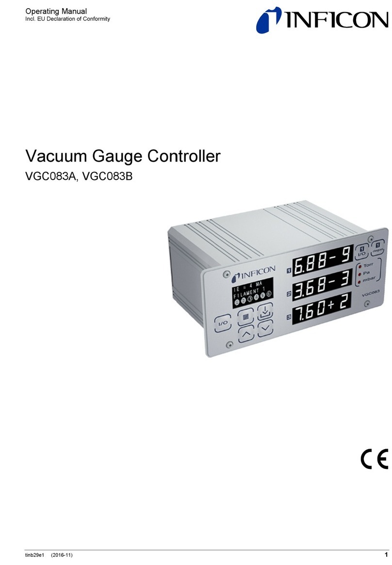
Inficon
Inficon VGC083B User manual
Inficon
Inficon IC6 User manual
Inficon
Inficon SQC-310 User manual
Popular Controllers manuals by other brands

ZPA Pečky
ZPA Pečky MODACT MTN 15 Mounting instructions
Regin
Regin RVAN10-24 Instruction

IR Ingersoll Rand
IR Ingersoll Rand ARO user manual
Siemens
Siemens SIMATIC S7-1500R/H manual
Mitsubishi Electric
Mitsubishi Electric MELSERVO-JET MR-JET-G Series user manual
Brooks Instrument
Brooks Instrument 5850EM Installation and operation manual
