Harken R27 User manual

Please read these instructions carefully before installing, servicing, or operating the equipment.
This manual may be modified without notice. See: www.harken.com/manuals for updated versions.
PLEASE SAVE THESE INSTRUCTIONS
ACCESS RAIL SYSTEM – R27
User Manual – Intended for specialized personnel or expert users
4684.1 7-29-13
This manual applies to cars shipped from Harken USA as of February 2011. Cars have serial numbers of A0633 and B0768.
WARNING! This product is part of a personal fall arrest system. The user must follow the
manufacturer’s instructions for each component of the system. These instructions must be
provided to the user of this equipment. The user must read and understand these instructions
before using this equipment. Manufacturer’s instructions must be followed for proper use and
maintenance of this equipment. Alterations or misuse of this equipment, or failure to follow
these instructions, may result in a fall or failure to arrest a fall leading to serious injury or death.

2 Access Rail System – R27
Parts Description
Part
No. Description
Length Width Maximum working load
Commentsmm in mm in kg lb
HC9565* R27 Access Rail car/pinstop 132 5
3
/
16
70 2
3
/
4
135 297.68 Use to hang tool bag, etc.
HC9608* R27 Access Rail car 273 10
3
/
4
70 2
3
/
4
135 297.68
HC10614* R27 Access Rail car/pinstop/wheel toggle 132 5
3
/
16
70 2
3
/
4
135 297.68
HC10615* R27 Access Rail car/wheel toggle 132 5
3
/
16
70 2
3
/
4
135 297.68
HC10612 R27 Wheel toggle 115 4
1
/
2
25 1 — — —
H-50547 Car coupler Use to couple two cars. Includes two stainless steel fasteners and clear plastic washers.
*Available with black Hard Lube or clear-anodized finish. Add .CLEAR to part number for clear anodizing.
Optional Parts
Part
No. Description
Length Mounting hole spacing Fasteners
m ft/in mm in mm in
1643.3m* R27 pinstop rail for countersink fasteners 3 9'10
1
/
16
" 100 3
15
/
16
8 FH
5
/
16
FH
1643.3.6m* R27 pinstop rail for countersink fasteners 3.6 11'9
3
/
4
" 100 3
15
/
16
8 FH
5
/
16
FH
1643.6m* R27 pinstop rail for countersink fasteners 6 19'8
1
/
4
" 100 3
15
/
16
8 FH
5
/
16
FH
1649 Splice link (Purchase one 1649 splice link for each 1643 rail section)
1650.3m* R27 pinstop rail for caphead fasteners 3 9'10
1
/
16
" 50 1
31
/
32
8 SHCS**
5
/
16
SHCS**
1650.3.6m* R27 pinstop rail for caphead fasteners 3.6 11'9
3
/
4
" 50 1
31
/
32
8 SHCS**
5
/
16
SHCS**
1651 Splice link (Purchase one 1651 splice link for each 1650 rail section)
HC9561* Endstop pair (Use one at each end of system rail)
*Available with black hardcoat or clear-anodized finish. Add .CLEAR to part number for clear anodizing **Socket Head Cap Screw
Rail and Accessories
Car Assembly
Part
No. Description
Length Width
Maximum
working load
Commentsmm in mm in kg lb
HC9606* R27 Access Rail car assembly/coupler 273 10
3
/
4
70 2
3
/
4
135 297.68 CE-approved system
See drawing
H-49971 on page 11
Includes: 1 x HC9565; 1 x HC9608; 1 x H-50547
HC10567* R27 Access Rail car assembly/coupler/wheel toggle 273 10
3
/
4
70 2
3
/
4
135 297.68
Includes: 1 x HC10614.CLEAR; 1 X HC10615.CLEAR; 1 X H-50547
*Available with black Hard Lube-anodized or clear-anodized finish. Add .CLEAR to part number for clear-anodizing.
External access cars must only be used with rail mounted using 5/16" (8 mm) fasteners except when using 1644 rail. Use only endstops listed below.
Car
Coupler
Forged Stainless
Steel Shackle
Pivot Pin
Retaining Screw
Working Car
Car Coupler
Screw/Pivot Pin
Retaining Screw
Pivot Pin
Retaining Screw
Forged Stainless
Steel Shackle
HC9606
Lever-actuated pinstop unlocked
Lever-actuated pinstop locked
HC10567.CLEAR
Add .CLEAR to part number for clear-anodized finish
HC9606.CLEAR
Pinstop Rail
1643.3m.CLEAR; 1643.3.6m.CLEAR
1643.6m.CLEAR; 1644.3m.CLEAR
1644.3.6m.CLEAR; 1644.6m.CLEAR
Wheeled toggle
attachment achieves
angles up to 90°
Endstop (Pair)
HC9561.CLEAR
Splice Link
1649
Car Coupler
H-50547
Access Rail Car/
Wheel Toggle
HC10615.CLEAR
Access Rail Car/
Pinstop/Wheel Toggle
HC10614.CLEAR
Access Rail Car
HC9608.CLEAR
Access Rail Car/Pinstop
HC9565.CLEAR
Fall Arrest Car
Lever-Actuated
Pinstop
Endstop (Pair)
HC9561
Access Rail
Wheel Toggle
HC10612.CLEAR
Pinstop Rail
1650.3m, 1650.3.6m
Pinstop Rail
1643.3m, 1643.3.6m
1643.6m
Splice Link
1651

Access Rail System – R27 3
1) Applications
A PURPOSE
The rail and car system is designed for
use as an adjustable anchorage point
for external access to facilitate external
maintenance on vessels.
The system has two anchorage points.
One anchorage point for a personal
suspension system and the second
for the fall-arrest system.
Free Fall: Personal fall arrest systems used with this equipment must be rigged to limit the free fall to no
more than 1.8 m (6 ft). Personal Suspension System must be rigged so that no vertical free fall is possible.
Fall Clearance: There must be sufficient clearance below the user to arrest a fall before
the user strikes the ground or other obstruction. Height of
user plus extended safety lanyard length must not be more
than the height from rail to ground minus 2 m (6.5 ft).
Swing Falls: Minimise swing falls by working as close to
the anchorage point as possible.
Load Angle Limitations: Harken cars beginning with A0633 and
B0768 with 8 mm shackles have the ability to handle loading at an
angle up to 15° beyond vertical. Loads beyond 15° from vertical
will overload car. See drawing at right. Exception: HC10567
wheel toggle cars can handle greater angles. See next page.
Training: This equipment must be installed and used by
persons trained in its correct application and use.
2) System Requirements
C STANDARDS
This system has been tested to EN 795:2012 standard and is appropriate
for single person use with an energy absorber to EN355.
Harken equipment is designed for use with Harken approved components. Substitutions or replacements made
with non-approved components may jeopardize compatibility of equipment and may affect the safety and reliability
of the system.
Connectors (hooks, carabiners and D-rings) must be capable of supporting at least 22kN (5000 lbs), in
accordance with EN362.
Personal Fall Arrest Systems used with this equipment must meet EN813 requirements and include a shock-
absorbing lanyard (to EN355 standard) and a full body harness (to EN361, EN358, EN813 standard).
WARNING! Consult Harken when using this equipment in combination with components or subsystems
other than those described in this manual. Altering or intentionally misusing this equipment may cause
the system to fail which can cause a fall which could result in severe injury or death.
B LIMITATIONS
Capacity: This system is designed for use by one person with a combined weight (clothing, tools etc) of no more
than 135 kg (297.68 lb). No more than one person may be connected to a two-car assembly at one time.
1. FULL-BODY SAFETY HARNESS
Use a full-body safety harness attached
to access car with pinstop.
Full-body safety harness must meet
/ANSI support standards.
2. WORKING HARNESS CAR
Use a working harness or chair attached
to access car. Working harness or chair
must meet /ANSI support standards.
3. TOOL SERVICE CAR
Add an optional car and coupler to work as
your tool service carrier.
15°
Harken HC9606 cars
beginning with A0633 and
B0768 with 8 mm shackles
have the ability to handle
loading at an angle up to
15° beyond vertical. Loads
beyond 15 degrees from
vertical will overload car.
Check CE label on side of
car for serial numbers.
12 3

4 Access Rail System – R27
3) Installation
PLAN SYSTEM
Consider all factors that will affect safety during use of this equipment.
Rail must be laid out and positioned as determined by a naval architect
or other suitably qualified person.
User must ensure that distance required to arrest fall is less than
obstruction below. Height of user plus extended safety lanyard length
must not be more than the height from rail to ground minus 2 m (6.5 ft).
Installer shall ensure suitability of base materials into which rail is fixed and that it is capable of sustaining test
force as detailed in standard EN 795:2012.
The following publications give detailed information to ensure safe and legally compliant installation. EN 795:2012
– Protection against falls from a height – Anchor devices – Requirements and Testing. BS 7883:2005 – Code of
practice for the design, selection, installation, use and maintenance of anchor devices conforming to BS EN 795.
MGN422 (M) – Use of Equipment to undertake work over the side on yachts and other vessels. (see Appendix A).
Harken External Access System – Installation and Proof Testing Advice. (see Appendix B).
Avoid attaching system components where suspension and/or fall arrest rope may come
in contact with, or abrade against, unprotected sharp edges.
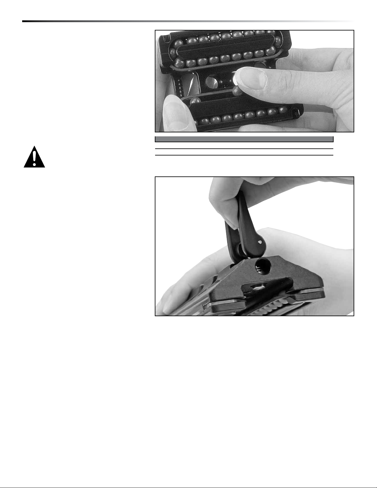
HC1057 CAR ASSEMBLY/WHEEL TOGGLE
This car is designed to run along a surface, mounted so that the toggle
overhangs the edge. Ensure that the whole wheel width is in good contact
with the surface to which the rail is attached. Ensure that the surface is
strong enough to sustain the expected working load and wear.
RAIL INSTALLATION
This Access Rail system should be installed only by a competent person or competent organization.
All rail listed in this manual is designed to use stainless steel fasteners. Attachment to vessel
must be in accordance with MGN 422(M). Harken does not recommend installing with aluminum
fasteners. Use of non stainless steel fasteners is at the liability of the installer and must be designed
to meet the requirements of MGN 422(M) in Appendix A and Proof Testing in Appendix B.
Always use threadlocking solution or locknuts.
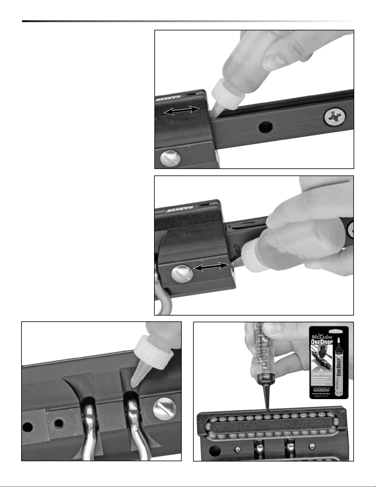
Precise rail alignment at joints is critical for smooth-running cars. Use Splice Links, Part
1649 (1643 rail) or Part 1651 (1650 rail), and round rods and spring clamps to align rail
during installation. Use transfer punch to mark hole centers. Keep rail in alignment, until
secured, with spring or "C" clamps when marking, drilling holes and inserting fasteners.
To prevent cars from rolling off rail, fasten endstops to rail ends using M8 (5/16")
stainless steel fasteners.
All rail and endstop fasteners must be coated with an anti-corrosion compound such as Tef-Gel®.
Installer must ensure that instructions and limitations of use are clearly displayed close to system. This should
include a statement that it is designed exclusively for use of personal protective equipment.
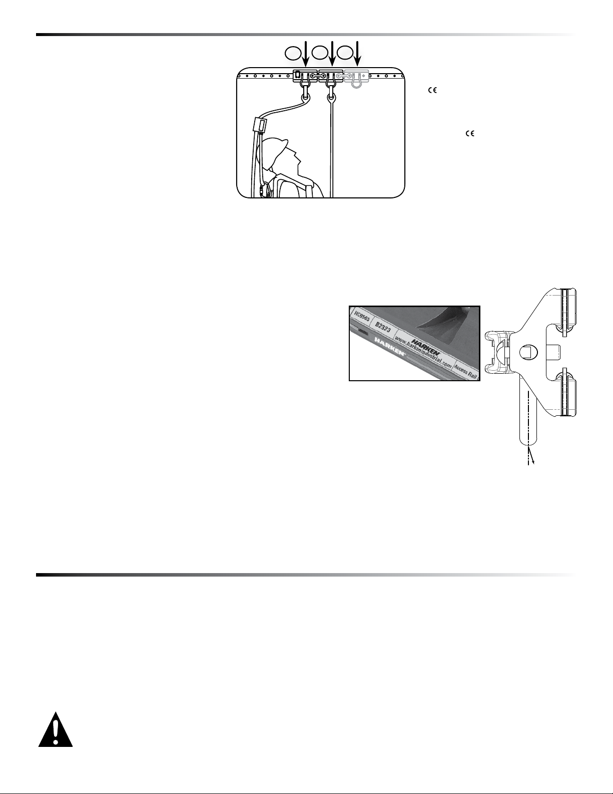
Rail should run horizontal to water plane, but can be mounted at various angles on this horizontal structure.
INCORRECT
CORRECT
Ceiling Mount Wall Mount
Mounted on angle:
cars with wheel
toggle face outward
Mounted in recess: cars with wheel
toggle for loading over an edge
Wheel Toggle Car
Use transfer punch to mark
hole centers. Hold rail in
alignment, until secured, with
spring or "C" clamps when
marking and drilling holes.

Access Rail System – R27 5
It is the responsibility of the user and the purchaser of this equipment to assure that they are familiar with these
instructions, trained in the correct care and use of, and are aware of the operating characteristics, application
limits, and the consequences of improper use of this equipment.
PERSONAL FALL ARREST EQUIPMENT
When using a hook with positive locking mechanism to connect to car shackle, ensure roll-out cannot occur.
Roll-out occurs when interference between hook and mating connector causes hook gate to unintentionally open
and release.
Self-locking snap hooks and carabiners should be used to reduce possibility of roll-out. Do not use hooks or
connectors that will not completely close over attachment object.
Follow manufacturer’s manual for correct use of energy-absorbing lanyard.
Follow manufacturer’s instruction manual for correct use of bosun’s chair and certified safety harness.
Do not attach a connector such that it will impact on the side of the car when in use.
WARNING! This product is part of a personal fall arrest system. The user must follow the manufacturer’s
instructions for each component of the system. These instructions must be provided to the user of this
equipment. The user must read and understand these instructions before using this equipment. Manufactur-
er’s instructions must be followed for proper use and maintenance of this equipment. Alterations or misuse
of this equipment, or failure to follow these instructions, may result in a fall or failure to arrest a fall leading
to serious injury or death.
4) Use
5) Training
6) Inspection
INSPECT BEFORE EACH USE
A formal inspection of the rail and its connection to the structure must be
performed at least annually by a competent person other than the user.
The inspection should be recorded in an inspection and maintenance log.
BEFORE EACH USE
A) Inspect pinstop for spring degradation, cracks or wear that may affect locking
strength and operation. Check drive pin holding plastic latch to post to make sure
it is secure.
WARNING! If pinstop locking mechanism fails cars may become loose
on rail resulting in an uncontrolled slide along rail resulting severe
injury and death.
A
Drive Pin
C
E
B
A
D
B BB
C
After a Fall: Any equipment which has been subjected to the forces of arresting a fall must be removed from
service immediately and destroyed by user or an authorised person.
Rescue: when using this equipment, the employer must have a rescue plan and the means at hand to implement it
and communicate that plan to users, authorised persons, and rescuers.

6 Access Rail System – R27
6) Inspection
WARNING! If car has been removed from rail
some balls may be lost. Do not use cars if balls
are missing. Cars with missing balls may come
off rail resulting in a fall, severe injury and
death. See page 8.
B) Inspect Pivot Pin Retaining Screws in cars and
coupler. Make sure Coupler/Pivot Pin Retaining Screws
have not loosened and are tightened securely in coupler.
If loose, remove screw, apply Red Loctite®and tighten.
CORRECT INCORRECT
E E
If car has been removed from rail, make sure car
contains all 60 balls. Do not load car assembly if
balls are missing.
WARNING! If all screws are not fastened securely,
rail can separate from mounting surface
resulting in a fall, severe injury and death.
C) Inspect shackles for signs of corrosion, cracks, or
elongation. If damaged, do not use. Damaged shackles
can indicate that car was overloaded. Return complete
car assembly to one of the service centers/recertification
centers listed on back of manual for advice.
D) Check all rail screws to make sure they have not
loosened and are flush with top of rail. Screws must be
flush with top of rail to allow cars to roll smoothly.
Loose screws can also compromise system safety.
WARNING! If screws loosen, shackle pivot pin can
move, allowing shackle to suddenly release from
car resulting in a fall, severe injury and death.
CORRECT INCORRECT
BB
CORRECT INCORRECT
BB
INCORRECT
B
E) Inspect endstop screws to make sure they have not
loosened and are flush with top of endstop.
WARNING! If endstop screws loosen cars can
roll off end of rail resulting in a fall, severe
injury and death.

Access Rail System – R27 7
Remove and inspect cars for damage, corrosion,
strength and operation.
Remove shackle from car to inspect hidden portion.
A) Remove Car Coupler/Pivot Pin Retaining Screw. If
necessary heat screw with a propane torch to break
red Loctite®bond.
B) Tip car so Pivot Pin slides out.
C) Remove shackle and inspect. If it shows any sign
of corrosion cracking or wear, return complete car
assembly to a service/recertification center listed on
the back of this manual for advice.
D) Reassemble parts using red Loctite®.
6) Formal Inspection
A
C
D E
A formal inspection of rail for cracks, deformation or
wear and its connection to structure must be
performed annually by a trained person.
Record inspection results in a log. See page 10.
B

8 Access Rail System – R27
To replace lost balls, position car on edge
with retaining clip in place. Do not remove
retaining clip. Gently push one ball at a
time into car from center of clip. Allow
balls to roll into return race and insert
remaining balls. Do not overfill each
car must have 60 balls!
Inspect pinstop for spring degradation,
cracks or wear that may affect locking
strength and operation.
Inspect rail for cracks, deformation
or wear.
Inspect attaching fasteners for loosening,
damage or corrosion that may affect
strength.
See Inspection “BEFORE EACH USE”,
pages 5, 6, 7.
SERVICE
If inspection reveals an unsafe or defective condition, remove item from service and destroy it.
If in doubt please contact manufacturer for further advice.
6) Inspection
Car Balls/Car Balls Order Balls/Set Ball Ø
HC9606 60 Torlon®1526 25
5
/
16
"(8mm)
HC9565/HC9608 60 Torlon®1526 25
5
/
16
"(8mm)
Inspect cars' Torlon®ball bearings.
Make sure there are no ‘flats’ as they will
impede car movement. Damaged balls
may indicate high load or high wear.
Return complete car assembly to one
of the service/recertification center listed
on the back of this manual for advice.
Make sure that all races have the correct
number of balls (see chart below/right).
Do not use system until missing balls
have been replaced.
WARNING! Do not use cars if balls
are missing. Cars with missing
balls may come off rail resulting in
a fall, severe injury and death.
Loctite®is a registered trademark of Henkel AG & Company KGaA.
Tef-Gel®is a registered trademark of Ultra Safety Systems, Inc.
Torlon®is a registered trademark of Solvay Advanced Polymers.

Access Rail System – R27 9
Flush cars frequently by squirting a
detergent/water solution into center
openings. Roll car back and forth to
distribute evenly, then flush bearings
with fresh water.
After car dries, apply one or two drops
of McLube®OneDrop™. Roll car back and
forth to distribute. Do not use spray
lubricants because ball bearings may
skid not roll.
It is important to clean car as excessive
build-up of grease, dirt and salt will
restrict car movement.
7) Maintenance
Cleaning and Flushing Point
Cleaning and
Flushing Point
After car dries, apply one
or two drops of McLube®
OneDrop™. Roll car back
and forth to distribute.

10 Access Rail System – R27
8) Labeling
EQUIPMENT RECORD
Product:
Model/Type Description Serial Number
Manufacturer
HARKEN
Address
N15W24983 Bluemound Rd
Pewaukee, WI 53072-4974USA
Tel/Fax/Email/Website
(262) 691-3320 / (262) 701-5780
Year of Manufacture Purchase Date Date First Put Into Use
Other important information (i.e. document number):
A record must be kept for each component, subsystem and system, with the following details (see example record log
below).
It is the responsibility of the user organisation to provide the record and to enter onto the record the details required.
EXAMINATION/REPAIR HISTORY
Date Reason for Entry
(Periodic exam or repair)
Defect notes, repairs carried out and
other important information
Name and signature of
compentent person
Date of next periodic
examination
9) Records
The following is an example and explanation of the product labelling:
1. Product part number; 2. Serial number; 3. Manufacturer’s name; 4. Product name; 5. Number of document to which
the equipment conforms; 6. CE symbol; 7. Pictogram indicating the necessity for users to read the instructions for use
and label part number.
HC9608 A0000 www.harkenindustrial.com Access Rail System R27 EN 795:2012 0321
4686
1 2 34 5 6 7
Loctite®is a registered trademark of Henkel AG & Company KGaA
McLube™is a registered trademark of McGee Industries, Inc.
Torlon®is a registered trademark of Solvay Advanced Polymers.

Access Rail System – R27 11
Drawing H-49971

12 Access Rail System – R27
Appendix A
MARINE GUIDANCE NOTE
MGN 422 (M)
Use of Equipment to Undertake Work Over the Side
on Yachts and Other Vessels
Notice to all Shipowners, Masters and Crew
This notice should be read with the Code of Safe Working Practices for
Merchant Seamen Chapters 4 and 15
PLEASE NOTE:-
Where this document provides guidance on the law it should not be regarded as definitive.
The way the law applies to any particular case can vary according to circumstances - for
example, from vessel to vessel and you should consider seeking independent legal advice if
you are unsure of your own legal position.
Summary
This MGN provides guidance on the use of “rail and trolley” and similar systems for
undertaking “overside” work on yachts and other vessels. The main points are:
•to ensure that new systems comply with BS standards;
•to ensure that existing systems have been checked to an equivalent standard;
•to ensure operators have been trained in their use;
•to ensure maintenance is carried out to the manufactures advice
Annex 1 give details of the relevant legislation that applies and Annex 2 give details of testing
and operation.
1. Introduction
1.1 The use of single point safety “rail and trolley” systems is becoming more prevalent on
vessels, especially mega-yachts. These allow crewmembers to work outside conventional
guardrails for cleaning and maintenance purposes on yachts or other vessels. In recent
years there have been a number of accidents using substandard equipment of this type.
Also there has been evidence that the manufacturers’ instructions on their use are not
being followed. The purpose of this notice is to give guidance on their use.
1.2 Most consist of two travellers linked in tandem that can be separated if necessary into
independent units. These are fitted to a metal track rail which allows the travellers to glide
along it. There is the option of having more than one traveller on the rail. However, many of
these systems have been designed, and installed, for the sole purpose of sail handling and
not for supporting workers working over the side of the vessel.
1.3 Equipment which is used for lifting persons must be designed for the purpose and it is not
acceptable to use a work station harness or a bosun’s chair attached to a rail and trolley
system designed for sail handling to enable window cleaning or other overside
maintenance to be undertaken.
- 1 -

Access Rail System – R27 13
Appendix A
2. Installation
2.1 Any newly installed rail and trolley system used should be tested, certified and approved to a recognised European
Union standard for fall protection equipment (EN 795:2012) and should display the CE mark. More information
on these requirements is contained in Annex 2.
2.2 Where it is proposed to use a rail and trolley system, or other system, (ie. a system already fitted) that has not
been specifically designed for supporting crew members over the side, its use for overside work is not permitted
without written confirmation having been received from the manufacturer, preferably by means of a certificate,
that use for such purposes is permissible including any conditions attached to its use for that purpose.
3. Operation
3.1 Before use the employer should ensure that:
3.1.1 the manufacturers’ instructions are read and understood by the persons who will be using the equipment;
3.1.2 a risk assessment is carried out and an appropriate rescue plan developed to recover persons who fall into
the water; and
3.1.3 crew members are competent to use the equipment and are aware of any conditions relating to its use
and their safety.
3.2 Rail and trolley systems for working overside should not be used whilst the vessel is underway.
3.3 These systems are designed to be used with the appropriate PPE (harnesses, lanyards, fall arresters and other
devices).
3.4 On systems referred to in paragraph 2.1 there is a single attachment on each traveller designed to accommodate a
single line such as a harness. One of the travellers is fitted with a locking device. The device which locks the
traveller in position along the rail rail must ONLY be disengaged from the rail rail while the user is changing
position. Once the user is in position, the locking MUST be re-engaged to hold the car in position and limit the
user’s movement along the rail rail.
3.5 The user must NEVER rely on only one attachment point for personal protective equipment. The working harness
should be attached to one traveller and a fall arrestor, or other safety device, to the other. A third traveller could
be used to attach work tools.
3.6 More guidance can be found in the Code of Safe Working Practices Chapters 4 and 15.
3.7 The use of systems for overside work that do not meet the requirements of either paragraphs 2.1 or 2.2 above, or
fail to provide instructions in the use of such equipment in accordance with paragraph 3.1, could potentially place
the employer of the crew, and also the master, in breach of their obligations under relevant Merchant Shipping
health and safety legislation and render them liable to prosecution and a fine for non-compliance. Further
information on relevant legislation is set out in Annex 1.
4. Maintenance
4.1 Where systems meeting the requirements of either paragraphs 2.1 or 2.2 are used for overside work, relevant
information regarding the maintenance and testing of such systems should be obtained from the system
manufacturer. Such information is to be in written form and a copy of it is to be kept on board the vessel
to which it applies.
4.2 More information on the use of these systems is contained in Annex 2.

14 Access Rail System – R27
Appendix A
More Information
Seafarer Safety and Health Branch
Maritime and Coastguard Agency
Bay 1/29
Spring Place
105 Commercial Road
Southampton
SO15 1EG
Tel : +44 (0) 23 8032 9328
Fax : +44 (0) 23 8032 9251
MCA Website Address: www.mcga.gov.uk
File Ref: MC122/6/0026
Published: September 2010
Please note that all addresses and
telephone numbers are correct at time of publishing
© Crown Copyright 2010
Safer Lives, Safer Ships, Cleaner Seas
When printed by the MCA the material used contains a minimum 75% post-consumer waste paper
- 3 -

Access Rail System – R27 15
Appendix A
ANNEX 1
MERCHANT SHIPPING LEGISLATION RELEVANT TO OVERSIDE WORK
The following provisions of Merchant Shipping Legislation are relevant to overside work. However only the main
points especially relevant to the use or selection of rail and trolley systems are listed. In order to meet the require-
ments of the legislation completely it will be necessary to comply fully with all the requirements of this legislation.
1 Merchant Shipping and Fishing Vessels (Health and Safety at Work) Regulations 1997
1.1 Under regulation 5 of the Merchant Shipping and Fishing Vessels (Health and Safety at Work) Regulations
1997 (No 2962) (the "General Duties" Regulations), guidance on which is contained in Marine Guidance Note
MGN 20, a general duty is placed on an employer to ensure, so far as is reasonably practicable, the health
and safety of workers and other persons on board a UK registered vessel. In meeting this requirement the
employer is required to undertake a risk assessment to determine whether any risks to the health and safety
of workers will, or potentially could, arise in the normal course of their activities or duties. Where any such
risks, or potential risks, are identified the employer is required to take appropriate measures to either remove
such risks entirely or, where that is not possible, reduce those risks as far as is reasonably practicable. It is
for the employer to decide what measures are taken to reduce any risks.
2 Merchant Shipping and Fishing Vessels (Provision and Use of Work Equipment) Regulations 2006
2.1 In addition to the provisions of the General Duties Regulations referred to above, the provisions of the
Merchant Shipping and Fishing Vessels (Provision and Use of Work Equipment) Regulations 2006
(No 2183), guidance on which is contained in Marine Guidance Note MGN 331 (M+F), require an
employer to ensure that all work equipment made available to workers on the ship:
(a) is suitable for the work to be carried out; or
(b) is properly adapted for that purpose; and
(c) may be used by workers without impairment to their health or safety.
2.2 When selecting work equipment the employer is required to take into account the conditions under which the
work is to be undertaken and the characteristics of that work as well as having regard to any risks to the health
and safety of workers arising from the use of that work equipment. The employer must also ensure that any
work equipment is used only for operations, and under conditions, for which it is suitable. "Suitable" in this
context means suitable in any respect which it is reasonably foreseeable will affect the health and safety of
any worker. Any work equipment to be used by workers must be maintained in an efficient state, in efficient
working order and in good repair.
3 Merchant Shipping and Fishing Vessels (Lifting Operations and Lifting Equipment) Regulations 2006
3.1 Should the use of the access systems referred to in paragraph 1.1 of the main body of this MGN involve
raising or lowering of any worker it is likely the provisions of the Merchant Shipping and Fishing Vessels
(Lifting Operations and Lifting Equipment) Regulations 2006 (SI 2006/2184), guidance on which is contained
in Marine Guidance Note MGN 332 (M+F), could also apply. Under these Regulations an employer is required
to ensure that all lifting equipment is of adequate strength and stability having regard in particular to the stress
induced at its mounting or fixing point. In addition the Regulations provide that, except in exceptional
circumstances, no lifting equipment shall be used for lifting persons unless it is designed for the purpose.
4 Merchant Shipping and Fishing Vessels (Heath and Safety at Work) (Work at Height) Regulations 2010
4.1 The Merchant Shipping and Fishing Vessels (Heath and Safety at Work) (Work at Height) Regulations 2010
(No 332), guidance on which is contained in Marine Guidance.
Note MGN 410, require employers to ensure that work equipment used for work at height is the most suit-
able to ensure and maintain safe working conditions for workers using that equipment. The Regulations also
require the employer to select work equipment which is appropriate to the nature of the work to be performed
and is appropriate to foreseeable loads and stresses. In addition specific “Requirements for Rope Access and
Positioning Techniques” are set out in Schedule 3 to the draft Regulations.

16 Access Rail System – R27
ANNEX 2
PROTECTION AGAINST FALLS FROM A HEIGHT – ANCHOR DEVICES –
REQUIREMENTS AND TESTING
1. Anchor devices fitted on vessels must comply with EN795; 1996; Class D or similar.
2. The main requirements are that tests should be carried out on a sample of the medium to
which the anchor devices, in this case the traveller and bar to which it is attached.
3. A static test with a weight of 10kN should be applied for a period of no less than 3 minutes.
If there is more than one traveller, ie more than one load can be carried, an additional 1kN
for each attachment should be added. The device should suffer no distortion or damage.
4. A dynamic test consists of a 100kg mass being dropped a distance of 2.5m between the
anchor points of the traveller bar. Again there should be no damage to the structure. This
test should be repeated at the extreme anchor points and at an intermediate one.
5. Precise descriptions of the required tests can be found in BS EN 795:1997.
6. Below is an example of a traveller showing its construction.
Lanyard Attachment Points
End stop Tandem C (Optional Equipment Car Track Rail
. Below is a typical setup for attachments to the traveller.
.Full-Body Safety Harness
ched to the
. Working Harness
chair attached to
dditional Options
traveller or
ar
& Connector Plate)
7
1
Use a full-body safety harness atta
access traveller with lock.
ust meetFull-body safety harness m
CE/ANSI support standards.
2
Use a working harness or
the access traveller without lock.
etWorking harness or chair must me
CE/ANSI support standards.
A
3. Tool Service Car
Add an optional lockable
traveller with coupler to work
as your tool service carrier.
- 6 -
Appendix A
ANNEX 2
PROTECTION AGAINST FALLS FROM A HEIGHT – ANCHOR DEVICES –
REQUIREMENTS AND TESTING
1. Fixed rail anchor devices must comply with EN 795:2012.
2. Tests should be carried out on a sample of the medium to which the anchor devices, in this
case the traveller and bar, is attached. Each test should be repeated at the extremity and
intermediate anchor and at a joint.
3. A static test with a weight of 12kN should be applied for a period of 3 minutes.
The device should suffer no permanent deformation of more than 10 mm.
4. A dynamic test consists of a 100 kg mass being dropped so that it generates a fall arrest load
of 9kN. The anchor device shall not release the test mass. Increase the test mass to 300 kg for
3 minutes. The mass is held clear of the ground.
5. Precise descriptions of the required tests can be found in EN 795:2012.
6. Below is an example of a traveller showing its construction.
End Stop
Lanyard Attachment Points (Optional Equipment Car
and Connector Plate)
Tandem Car Rail

Access Rail System – R27 17
Appendix B
Harken Access Rail System (ARS)
Installation & Proof Testing Advice
INTRODUCTION
The following is the good faith interpretation by Harken of the standards that we understand are the current
methods that will meet the many test procedures to assure a safely installed Harken ARS System. Harken is
not responsible for any future changes, alternate interpretations, or other requirements imposed by inspection
officials. Harken does not accept any responsibility for the consequences of failed installations including but not
limited to personal injuries, costs or any related damages or from failed alternative installations methods. The
installer is directed to carefully consider BACKGROUND.
The Harken ARS is fully tested and certified under EN 795:2012 as a fall arrest anchor device. However, we
have had a number of requests to approve alternative methods of fastening due to different construction
and building techniques.
Regrettably, it is simply not possible for us to approve all these alternatives without detailed engineering, testing
and surveying of every individual case.
Therefore, the purpose of this guidance is to illustrate how alternative methods of attachment can be considered
by the installer and considered as suitable.
To be 100% explicit, this guidance is regarding the installation of the product and nothing to do with the product itself.
BACKGROUND
We have researched the MCA documentation and BS 7883:2005 PPE Anchor Device Testing. From this we can
draw two critical principals:
A) Any safety equipment or lifting device must have its installation inspected and surveyed as per standard
industry practice. Likewise, periodic inspection is necessary to ensure nothing has deteriorated due to age, wear or
corrosion. There are well established systems and protocols in place to ensure this is done. This is nothing special
or unique to the Harken ARS.
B) As per the MCA code of practice (Chapter 21.6.1) The Installer has the full responsibility for a proper, safe
installation that is tested to meet all relevant standards. Normally this would be verified by an independent safety
surveyor.
REGARDING BS 7883:2005
This Code of Practice details the maintenance and testing regime of EN 795:2012 anchor devices for fall protection.
It recommends an initial sample (3no.) proof test of 12kN (1200 kgs) for 3 minutes if the installation is into a base
material that the installer has no information on or has never installed into before. If the samples tested pass, the
rest of the anchor points shall be tested to 6kN for 15 seconds.
If the anchor device is only used for fall protection, the device should be thoroughly examined and tested annually
to 6kN for 15 seconds. If the device is used for suspending personnel or rope access the device should be
thoroughly examined and tested every 6 months as a minimum.
CONCLUSION
BS 7883:2005 standard gives a good reference point to offer guidance on testing of any rail installation, new or
retro-fit. Our interpretation in practical application is:
1. PROOF TESTING
1.1 The test objective is for the installer to prove their individual installation methodology for each type of base
material/fastener type or where working with unknown factors.
Appendix B

18 Access Rail System – R27
1.2 The surveyor will have to approve the individual test regime and be satisfied it was done correctly. In practice
this normally means overseeing the test.
1.3 For new builds or for identical constructions, the proof test can be done on representative sample pieces.
These should be long enough to hold a pair of cars in normal configuration plus the end stops. In practice,
500 mm would be suitable.
1.4 This can be applied to installations if the construction is identical and as long it is properly documented.
1.5 In the case of retro-fits where the construction is not necessarily known (due to modifications, corrosion
or aging), the proof testing will have to be done in situ.
1.6 If done in place, then we recommend testing in highest risk locations such as where personnel gain access
to the system or at the ends of the rails.
1.7 Subject to surveyor approval, the proof test procedure would be:
Note: This is a static test. There is no drop load. The car is not expected to move under these conditions
i. Attach a water bag to a single car.
ii. Fill to achieve a load of 1200 kg.
iii. Hold for 3 minutes without deformation – paying particular to rail/fastener stability.
iv. Drain/unload water bag, move and repeat in two further locations (or sample pieces).
v. The system should remain functional.
2. INSTALLATION TESTING:
2.1 This test objective is to ensure that the system has been installed correctly in practice and remains sound as it ages.
2.2 We recommend that each rail is tested in at least 3 locations, typically at both ends and at any rail joint or in
the middle.
2.3 Again subject to surveyor approval, each rail should be tested on installation as per:
i. Attach a water bag to a single car.
ii. Fill to achieve a load of 600 kg.
iii. Test for 15 seconds per location.
iv. Repeat as necessary for each separate rail.
2.4 Normal safety equipment operations requires testing post-installation and then 6 monthly routine inspection with
12 monthly testing.
2.5 Further testing and inspection of the ARS should be incorporated into standard operating practices and into the
safety records.
3.0 Documentation to be supplied after installation:
i. The installation documentation provides evidence to the end uses and that the installation has been carried
out properly.
ii. The documentation should be handed over to the user and kept on hand for subsequent examinations of
the device.
Appendix B

Access Rail System – R27 19
Appendix B
iii. The documentation should contain at least:
•Addressandlocationofinstallation.
•Nameandaddressofinstallationcompany.
•Nameofthepersoninchargeoftheinstallation.
•Productidentification.
•Fixingdevice.
•Schematicinstallationplan.
•Adeclarationbytheinstaller,thatitis:
Installed in accordance with manufacturer's instructions;
Carried out in accordance to plan;
Fixed as specified;
Commissioned in accordance with manufacturer's instructions;
Supplied with photographic information/documentation.
1/09/10
Andrew Ash-Vie
Managing Director, Harken UK Ltd
Updated in line with EN 795:2012
01/10/2012

Printed in USA 4684.1 07-13
Worldwide Limited Warranty
COVERAGE. HARKEN®warrants that each HARKEN product, when
properly used and maintained, will be free from defects in material
and workmanship from the date of receipt of the product by the
final customer.
THE LIMITED WARRANTY. This limited warranty applies to all
Harken products purchased.The sole and exclusive remedy under
this LIMITED WARRANTY for original defects in materials or work-
manship of a HARKEN product shall be the repair or replacement,in
HARKEN’s sole discretion, of the defective part or component, in
accordance with the terms of this warranty.
WARRANTOR. For products originally sold in the Unites States, the
limited warranty for the products is supplied by HARKEN, INC.. For
products originally sold in the European Union, the limited warranty
for the products is supplied by the dealer who sold the product
through the Harken Distributors in that country. For products origi-
nally sold in the rest of the World, the limited warranty for the prod-
ucts is supplied directly by the Harken Distributors in that country.
When“HARKEN” is mentioned throughout this Limited Warranty, it
refers to the entity as defined in this paragraph.
OWNER – NON-TRANSFERABLE WARRANTY. This warranty is
made by HARKEN with the original purchaser of the product and
does not extend to any third parties. The rights of the original
purchaser under this warranty may not be assigned or otherwise
transferred to any third party.
WARRANTY TERM. The LIMITED WARRANTY covers any original
defects in material or workmanship manifested within 12 months
of the date of receipt of the product by the final customer.
NOT COVERED. The LIMITED WARRANTY does not apply to, nor
shall HARKEN have any liability or responsibility for, damages or
expenses relating to defects caused by misuse, abuse, failure to
install, use, maintain or store the HARKEN product as specified in
the warranty booklet, service booklet, manuals, catalogue or other
literature available from HARKEN.
The LIMITED WARRANTY does not apply to, and neither shall
HARKEN have any liability or responsibility in respect to, damages
or expenses relating to:
•defectsinmaterialorworkmanshipthatdidnotexistwhenthe
product was first delivered;
•defectsinmaterialorworkmanshipthataremanifestedoutside
the warranty period;
•defectswhicharenotreportedtoHARKENwithinsixty(60)days
of discovery;
•aproductthathasbeenalteredormodifiedfromfactory
specifications;
•damageordeteriorationofcosmeticsurfacefinishes,including
cracking, crazing, discoloration or fading;
•accidents,misuse,abuse,abnormaluse,improperuse,lackof
reasonable or proper maintenance or storage;
•installation,serviceorrepairsimproperlyperformedorreplacement
parts or accessories not conforming to HARKEN’s specifications;
•useexceedingtherecommendedandpermittedlimitsorloadsof
the product and/or the product on which the product is installed;
•normalwearordeteriorationoccasionedbytheuseofthe
product or its exposure to the elements;
•ropes,lines,bucklesandwebbing;
•lossoftime,lossofuse,inconvenience,travelexpense,costs
related to procuring any substitute product, transportation costs,
any incidental or consequential damages arising out of the non-use
of the product, or compensation for inconvenience or loss of use
while the product is being repaired or otherwise not available, or
other matters not specifically covered hereunder;
•thecoststoremove,disassembleorre-installtheproduct;
•removal,storageandreplacingoftheproductonwhichtheproduct
has been installed, even where this is necessary to carry out the
warranty service.
The LIMITED WARRANTY does not cover, nor shall HARKEN have
any liability or responsibility in respect of, damages or expenses
relating to, the following products and/or components:
•washersandspacers;
•ballbearings,rollerbearings,thrustbearings.
Online warranty registration. Registering this product online at www.harken.com is critical to receive product updates or any recall
information. Harken will not sell this information or use it for solicitation.
SERVICE / RECERTIFICATION CENTERS
Manufacturer
N15W24983 Bluemound Rd., Pewaukee, WI 53072-4974
Telephone: (262) 691-3320 •Fax: (262) 701-5780 •Cable: Harken Pewaukee
EU Representative – Harken UK Ltd
Bearing House, Ampress Lane, Lymington, Hampshire S041 8LW, England
Telephone: (44) 01590-689122 •Fax: (44) 01590-610274
Web:www.harken.co.uk•Email:[email protected]
Other manuals for R27
2
Table of contents
Other Harken Safety Equipment manuals

Harken
Harken ACCESS RAIL INCAR1-CURVE User manual

Harken
Harken Protexit Blocks User manual

Harken
Harken Ti-Lite Carbo AirBlock 351 User manual

Harken
Harken R27 User manual

Harken
Harken T2 2146 User manual

Harken
Harken NINJA MULTIASCEND User manual

Harken
Harken T2 2146 User manual

Harken
Harken Access Rail R27 LS User manual

Harken
Harken 944 User manual

Harken
Harken E2700 User manual