USE ONLY HAYWARD GENUINE REPLACEMENT PARTS
HRSN2IOM Rev D ECR 102V
Page 3 of 36
Hayward Flow Control
1-888-HAY-INDL (1-888-429-4635) www.haywardowcontrol.com
This document has active links which can be
used with mobile devices. Simply touch a line in
the Table of Contents to go directly to that page.
Other active links function the same way. The
Back to TOC link at the bottom of each page
returns to the TOC or Wiring Diagram index.
Important Safety Instructions ......................2
Table of Contents ................................3
Actuator Operational Concepts ..................3
Technical Information ............................4
Conventions Used in this Manual ................4
Actuator Handling And Installation ..................5
Shipping and Handling ........................5
Installation Notes .............................5
Product Mounting And Setup ......................6
HRSN2A, 2R Specic ............................7
Rotation of HRSN2A, 2R Components .............7
Adjusting End of Travel Cams ....................8
Adjusting Auxiliary Switch Cams .................9
Proportional Control Setup .....................10
HRSN2B, 2S Specic ...........................11
Rotation of HRSN2B, 2S Components ............11
Adjusting End of Travel Cams ...................12
Adjusting Auxiliary Switch Cams ................13
Proportional Control Setup .....................14
Commissioning ................................15
On/Off Control ..............................15
Proportional Control .........................17
Proportional Calibration .........................18
120-230VAC Models .........................18
Proportional Calibration .........................20
12-24VAC/DC Models ........................20
Troubleshooting ................................22
On/Off Models ..............................22
Proportional Models .........................23
Mechanical Data ...............................24
HRS 2A~2S Except 12-24V Proportional .............24
Exploded View ..............................24
Dimensional Data HRS 2A, 2R ................25
Dimensional Data HRS 2B, 2S ................26
HRS 2A~2S 12-24V Proportional ...................28
Exploded View ..............................28
Dimensional Data HRS 2A, 2R ................29
Dimensional Data HRS 2B, 2S ................30
Wire Sizing Chart ...............................31
Auxiliary Switch Cam Mapping .................31
Wiring Diagrams ...............................32
HRSN2A~2S 12/24VAC/VDC On/Off ............32
HRSN2A~2S 12/24VAC/VDC Proportional ........33
HRSN2A~2S 120/230VAC On/Off ...............34
HRSN2A~2S 120/230VAC Proportional ..........35
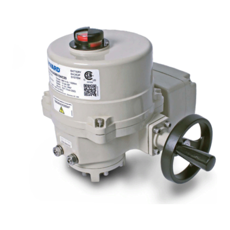
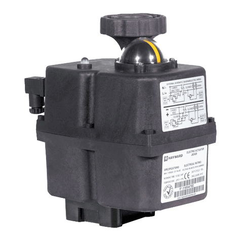
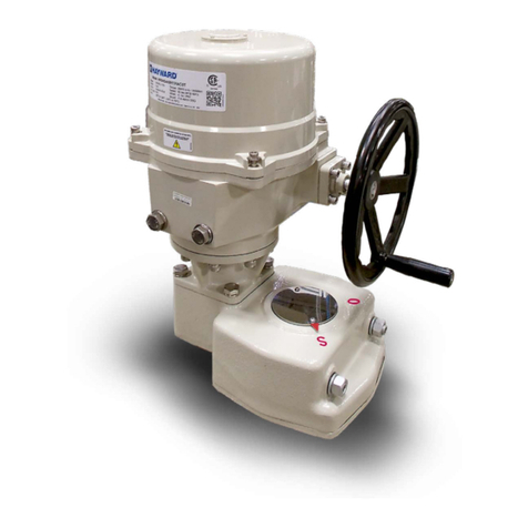
Notice: The HRSN2 Series is produced in two distinct versions: one with a manual override shaft on the bottom of the
actuator (HRSN2A & 2R), and the other with a manual hand wheel on the side of the actuator (HRSN2B & 2S).
Notice: ALL HRSN2 Series actuators rotate CW to CLOSE the output shaft (out the bottom of the actuator) when viewed
from ABOVE. On HRSN2A & 2R models, the cam shaft and the indicator rotate CW to close as well. However on
HRSN2B & 2S models, the cam shaft and the indicator rotate CCW (opposite the output shaft).
Notice: The calibration procedures are specic to each model. The HRSN2A & 2R use one common procedure, while the
HRSN2B & 2S use a second procedure common to those two models. Please be sure to follow the correct sequence for
your model.
Notice: HRSN2 Series actuators are fully assembled, calibrated and tested prior to leaving our factory. In most cases, after
you have mounted the actuator to your device, you should be able to operate the actuator from fully CLOSED (CW) to fully
OPEN (CCW) and back again, and nd that no adjustments are needed. The assembly can be put into service immediately.
However, should it be necessary to make adjustments to the end-of-travel positions to overcome any device related issues
(i.e. valve shaft incorrectly timed to the drive stem), the procedures outlined below should be followed to put the assembly
into service. Note that there is a maximum adjustment range of +/- 3° at each end of travel.
Pages 8-9 - Travel limits and Auxiliary switch cams, HRSN2A, 2R Series
Pages 12-13 - Travel limits and Auxiliary switch cams, HRSN2B, 2S Series
ACTUATOR OPERATIONAL CONCEPTS
TABLE OF CONTENTS
HRSN2 Series
Back to TOC
