HBM FIT 5A User manual

Operating Manual | Bedienungsanleitung |
Manuel d'emploi | Istruzioni per l'uso
English Deutsch Français Italiano
FIT®5A

Hottinger Baldwin Messtechnik GmbH
Im Tiefen See 45
D-64239 Darmstadt
Tel. +49 6151 803-0
Fax +49 6151 803-9100
www.hbm.com
Mat.: 7-2004.3916
DVS: A3916-2.0 HBM: public
03.2018
EHottinger Baldwin Messtechnik GmbH.
Subject to modifications.
All product descriptions are for general information only.
They are not to be understood as a guarantee of quality or
durability.
Änderungen vorbehalten.
Alle Angaben beschreiben unsere Produkte in allgemeiner
Form. Sie stellen keine Beschaffenheits- oder Haltbarkeits
garantie dar.
Sous réserve de modifications.
Les caractéristiques indiquées ne décrivent nos produits
que sous une forme générale. Elles n'impliquent aucune
garantie de qualité ou de durabilité.
Con riserva di modifica.
Tutti i dati descrivono i nostri prodotti in forma generica e non
implicano alcuna garanzia di qualità o di durata dei prodotti
stessi.

Operating Manual | Bedienungsanleitung |
Manuel d'emploi | Istruzioni per l'uso
English Deutsch Français Italiano
FIT®5A

2A3916-2.0 HBM: public FIT®5A
English
1 Safety instructions 3........................................
2 Markings used 6............................................
2.1 Symbols on the device 6......................................
2.2 The marking used in this document 7...........................
3 Conditions on site 8........................................
3.1 Protection against corrosion 8.................................
3.2 Deposits 8..................................................
4 Mechanical installation 9....................................
4.1 Important precautions during installation 9......................
4.2 Mounting and load application 9...............................
5 Electrical connection 11......................................
6 Interfaces 13................................................
6.1 Connection of several load cells to a PC via RS-485 13............
6.2 Connection to a PC with an RS‐232 interface via the HBM interface
converter 14.................................................
6.3 Connection to a CANopen interface 14..........................
6.4 Connection to a DeviceNet interface 14..........................
6.5 Diagnostic interface connection 14..............................
7 Inputs and outputs 16........................................
7.1 Inputs 16....................................................
7.2 Outputs 16...................................................
8 Operation via software 20....................................
9 Waste disposal and environmental protection 21..............
10 Specifications 22............................................
11 Dimensions 23..............................................

Safety instructions
FIT®5A A3916-2.0 HBM: public 3
1 Safety instructions
Appropriate use
Transducers of the FIT5A type series are designed solely for technical weigh
ing applications within the application limits detailed in the specifications. Any
other use is not appropriate.
Any person instructed to carry out installation, commissioning or operation of
the transducer must have read and understood the Operating Manual and in
particular the technical safety instructions.
In the interests of safety, the transducer should only be operated by qualified
personnel and as described in the Operating Manual. It is also essential to
comply with the legal and safety requirements for the application concerned
during use. The same applies to the use of accessories.
The transducer is not intended for use as a safety component. Please also
refer to the "Additional safety precautions" section. Proper and safe operation
requires proper transportation, correct storage, siting and mounting, and care
ful operation.
Operating conditions
SPlease observe the permissible maximum values stated in the specifica
tions for:
- Limit load
- Limit load at max. eccentricity
- Limit lateral loading
- Breaking loads
- Temperature limits
- Limits of electrical load-carrying capacity
SPlease note that when several transducers are installed in a scale, there is
not always an even distribution of load on the individual transducers.
SThe transducers can be used as machine elements. When used in this
manner, it must be noted that, to favor greater sensitivity, the transducer is
not designed with the safety factors usual in mechanical engineering.

Safety instructions
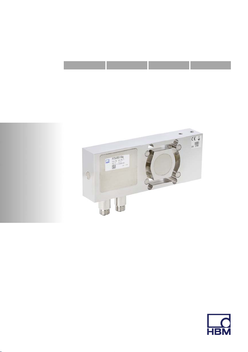
4A3916-2.0 HBM: public FIT®5A
SThe transducer must not be modified from the design or safety engineering
point of view except with our express agreement.
SThe transducer is maintenance-free.
SIn accordance with national and local environmental protection and material
recovery and recycling regulations, old transducers that can no longer be
used must be disposed of separately and not with normal household
garbage, see Chapter 9, Page 21.
Qualified personnel
Qualified persons means persons entrusted with the installation, fitting, com
missioning and operation of the product who possess the appropriate qualifica
tions for their function.
This includes people who meet at least one of the three following requirements:
SKnowledge of the safety concepts of measurement and automation techno
logy is a requirement and as project personnel, they must be familiar with
these concepts.
SAs measurement or automation plant operating personnel, they have been
instructed how to handle the machinery. They are familiar with the operation
of the equipment and technologies described in this documentation.
SAs commissioning engineers or service engineers, they have successfully
completed the training to qualify them to repair the automation systems.
They are also authorized to activate, ground and label circuits and equip
ment in accordance with safety engineering standards.
Working safely
SThe device must not be directly connected to the power supply system. The
supply voltage must be between 10 and 30 VDC.
SError messages should only be acknowledged once the cause of the error
is removed and no further danger exists.
SMaintenance and repair work on an open device with the power on may
only be carried out by trained personnel who are aware of the dangers in
volved.

Safety instructions
FIT®5A A3916-2.0 HBM: public 5
SAutomation equipment and devices must be designed in such a way that
adequate protection or locking against unintentional actuation is provided
(e.g. access checks, password protection, etc.).
SFor those devices operating in networks, safety precautions must be taken
both in terms of hardware and software, so that a line break or other inter
ruptions to signal transmission do not cause undefined states or loss of data
in the automation device.
SAfter making settings and carrying out activities that are password-protec
ted, ensure that any controls that may be connected remain in a safe condi
tion until the switching performance of the device has been tested.
Additional safety precautions
Additional safety precautions to meet the requirements of the relevant national
and local accident prevention regulations must be taken in plants where mal
functions could cause major damage, loss of data or even personal injury.
The scope of supply and performance of the transducer covers only a small
area of measurement technology. Before starting up the transducer in a sys
tem, a project planning and risk analysis must first be implemented, taking into
account all the safety aspects of measurement and automation technology so
that residual dangers are minimized. This particularly concerns personal and
machine protection. The transducers function passively and cannot implement
any (safety-relevant) cutoffs. In the event of a fault, the relevant precautions
must establish safe operating conditions.
General dangers of failing to follow the safety instructions
The transducer corresponds to the state of the art, and is reliable. The trans
ducer may give rise to residual dangers if it is inappropriately installed or oper
ated.

Markings used
6A3916-2.0 HBM: public FIT®5A
2 Markings used
2.1 Symbols on the device
Statutory waste disposal mark
In accordance with national and local environmental pro
tection and material recovery and recycling regulations,
old devices that can no longer be used must be disposed
of separately and not with normal household garbage.
Also see Section9 on Page21.
CE mark
The CE mark enables the manufacturer to guarantee that
the product complies with the requirements of the relev
ant EC directives (the Declaration of Conformity can be
found on the HBM website (www.hbm.com) under HBM
doc).

Markings used
FIT®5A A3916-2.0 HBM: public 7
2.2 The marking used in this document
Important instructions for your safety are specifically identified. It is essential to
follow these instructions in order to prevent accidents and damage to property.
Symbol Significance
WARNING This marking warns of a potentially dangerous situ
ation in which failure to comply with safety require
ments can result in death or serious physical injury.
Note This marking draws your attention to a situation in
which failure to comply with safety requirements can
lead to damage to property.
Important
This marking draws your attention to important in
formation about the product or about handling the
product.
Emphasis
See …
Italics are used to emphasize and highlight text and
identify references to sections, diagrams, or external
documents and files.

Conditions on site
8A3916-2.0 HBM: public FIT®5A
3 Conditions on site
Series FIT5A load cells are hermetically encapsulated and are therefore not at
all sensitive to the influence of moisture and humidity. The transducers achieve
protection class IP68 and IP69K in accordance with DIN EN60529. The load
cells should nevertheless be protected against the lasting influence of moisture
and humidity.
3.1 Protection against corrosion
The load cell must be protected against chemicals that could attack the trans
ducer body steel, or the cable.
Notice
Acids and all substances that release ions also attack stainless steels and their
welded seams.
The resultant corrosion can cause the transducer to fail. If this is the case, you
must provide appropriate means of protection.
3.2 Deposits
Dust, dirt and other foreign matter must not be allowed to accumulate suffi
ciently to divert some of the measuring force onto the housing, thus invalidating
the measured value (force shunt).

Mechanical installation
FIT®5A A3916-2.0 HBM: public 9
4 Mechanical installation
4.1 Important precautions during installation
SHandle the transducer with care.
SWelding currents must not be allowed to flow over the transducer. If there is
a risk that this might happen, you must provide a suitable low-ohm connec
tion to electrically bypass the transducer. HBM provides the highly flexible
EEK ground cable for this purpose, for example, that is screwed on above
and below the transducer.
SMake sure that the transducer cannot be overloaded.
WARNING
There is a danger of the transducer breaking if it is overloaded. This can cause
danger for the operating personnel of the system in which the transducer is
installed.
Implement appropriate safety measures to avoid overloads or to protect
against the resulting dangers.
Notice
Load cells are precision measuring elements and need to be handled carefully.
Dropping or knocking the transducer may cause permanent damage. Make
sure that the transducer cannot be overloaded, including while it is being
mounted.
4.2 Mounting and load application
Secure the load cells in the two mounting holes next to the connector socket(s)
(one or two sockets are present, depending on the version). A platform for load

Mechanical installation
10 A3916-2.0 HBM: public FIT®5A
application can be mounted on top. The screws and tightening torques to be
used are given in the table below:
Mounting Thread Min. property class Tightening torque 1)
On mounting plate M6 10.9 10N⋅m
For load application M6 10.9 10N⋅m
1) Recommendedvalue for the specified property class. Please comply with the screw
manufacturer's instructions with regard to screw dimensions.
Direction of loading
center of platform
max. 30.5
Adapter
(flatness v0.02mm on
the mounting surface)
Alternative load
application
Platform
Mounting base
(flatness v0.02mm on
the mounting surface)
max. 70.5
∅20
Device socket 2
(extended version E only)
Device socket 1
Fig. 4.1 Load application and installation
Important
The surface flatness of the components mounted on the load cell must be bet
ter than 0.02 mm.

Electrical connection
FIT®5A A3916-2.0 HBM: public 11
5 Electrical connection
Notice
Electronic components are sensitive to electrostatic discharge (ESD). So you
must discharge your own static electricity before touching the connector plugs.
The standard version of the load cell comes with an 8‐pin device socket. The
extended version E has a second 8-pin device socket.
Device sockets 1 and 2
8
2
3
4
5
1
7
6
Fig. 5.1 M12 device socket, 8‐pin

Electrical connection
12 A3916-2.0 HBM: public FIT®5A
Connection Device socket 1
RS‐485 CANopen/DeviceNet
1 GND1) GND
2Diag RbTb or not used2) Diag RbTb or not used 2)
3 RA CAN‐High IN
4Diag RaTa or trigger2) Diag RaTa or trigger 2)
5 RB CAN‐Low IN
6 TB CAN‐Low OUT
7 TA CAN‐High OUT
8 UB1 UB1
1) In extended version E, you must connect GND (pin 1) of device socket 1 to GND of the voltage
supply of the second device socket (inputs/outputs). See Section 7, Page 16.
2) The standard version S does not have a diagnostic channel. Pin 4 is then the trigger input, pin 2
must not be connected.
Connection Device socket 2 (extended version E) 1)
1 -
2 IN2
3 OUT2
4 IN1
5 OUT4
6 OUT3
7 OUT1
8 UB21)
1) The signals apply to GND of socket 1. You must connect the GND wire of the voltage supply of
device socket 2 to pin 1 (GND) of device socket 1, as device socket 2 does not have a connection
for this. See Section 7, Page 16.
Suitable connection cables and the color code used can be found in the HBM
data sheet "Cables with a plug", B3643.

Interfaces
FIT®5A A3916-2.0 HBM: public 13
6 Interfaces
The load cell can be provided with an RS‐485 interface, a CANopen interface,
or a DeviceNet interface, as required. The reference potential of all the inter
face signals is GND (supply ground) of device socket 1.
6.1 Connection of several load cells to a PC via RS-485
Line termination Line termination
TB
TA
RB
RA
PC = Master FIT5A_1 = Slave 01 FIT5A_89 = Slave 89
...
500 Ω
500 Ω
500 Ω
500 Ω
500 Ω
500 Ω
500 Ω
500 Ω
+5 V
+5 V
+5 V
+5 V
TxD on/off RxD
TB TA
TR
RB RA
TxD on/off RxD
TB TA
TR
RB RA
TxD on/off RxD
TB TA
TR
RB RA
Fig. 6.1 Bus connection via RS‐485
Up to 89 load cells can be connected via the RS‐485 interface to a common
bus line, the total length of which can be as much as 1000 m. Bus cabling for
4wiremode is shown in Fig. 6.1.
Remember that many PCs do not have an RS‐485 interface. In this case, you
need an interface converter, such as the HBM converter (see Section 6.2).

Interfaces
14 A3916-2.0 HBM: public FIT®5A
6.2 Connection to a PC with an RS‐232 interface via the
HBM interface converter
RS‐232 8...30V
2/4-wire
RS‐485
TxD
RxD
GND
RxD
TxD
GND
Interface converter
RS‐232 - RS‐485
PC COM port
D-Sub plug, 9-pin
(PC)
PIN
2 = RxD
3 = TxD
5 = GND
UB: 10 …30VDC
RS‐485 bus
TA
TB
RA
RB
GND
Uv
TA (blue)
TB (black)
RA (green)
RB (gray)
GND
Uv(red, 10 ... 30VDC)
(white)
Equivalent designations:
TA = T-
RA = R-
TB = T+
RB = R+
D-Sub socket, 9-pin
(converter)
PIN
2 = TxD
3 = RxD
5 = GND
FIT5A
Fig. 6.2 Connection to a PC via the HBM interface converter
6.3 Connection to a CANopen interface
The interface is set up using the CANopen standard DS301. The load cell ad
dress on delivery is 63.
6.4 Connection to a DeviceNet interface
The interface is set up using the DeviceNet specification, Release 2.0 ODVA.
The load cell address on delivery is 63.
6.5 Diagnostic interface connection
The real time values stored with the diagnostic function can be read out via this
interface. The load cell address on delivery is 31, the baud rate is fixed at
38600Bd.

Interfaces
FIT®5A A3916-2.0 HBM: public 15
T/RB
T/RA
PC = Master FIT5A_1 = Slave 01 FIT5A_31 = Slave 31
...
500 Ω
500 Ω
500 Ω
500 Ω
+5 V
+5 V
TxD on/off RxD TxD on/off RxD TxD on/off RxD
Fig. 6.3 Connecting the diagnostic interface

Inputs and outputs
16 A3916-2.0 HBM: public FIT®5A
7 Inputs and outputs
7.1 Inputs
Apply the control signals between the particular input and reference potential
(GND). In the standard version, the trigger input can be directly activated with
a logic signal (HCMOS), although voltages up to 12V are also possible. The
inputs of device socket 2 are suitable for the signals of a PLC. The reference
potential in both cases is GND of device socket 1. The table below shows the
allocation of logic states to the voltage values at the input. Levels between the
stated high and low levels produce undefined states!
Trigger input Inputs IN1, IN2
Reference potential GND GND
High level >4V >10V
Low level <1V <6V
Input resistance 70kΩ9kΩ
Function External trigger TAR, Break, RUN functions
Quiescent level High or low level1Low level
Triggering event Transition from high to low
level
High level, debounced 2
1) Stable level at trigger input used. The other wire must be at low level or not connected.
2) Debouncing is dependent on the function set (IMD command), but not on the input used (device
socket 1 or 2).
7.2 Outputs
The output driver of the switch outputs is a PLC compatible static switch (High-
Side driver). Power for switching must be supplied via external operating
voltage UB2. All the voltages apply to GND at device socket 1.
When an output is activated, a positive level is given on the corresponding out
put line, voltage is dependent on UB2. The connected consumer is between the
output and the GND potential of the switching load supply:

Inputs and outputs
FIT®5A A3916-2.0 HBM: public 17
Important
No GND potential is present at device socket 2, so you must connect the refer
ence potential (GND) of the load circuits with GND at device socket 1.
There are two distinctive cases when connecting GND potential:
1. The arrangement of the function blocks, i.e. the digital part for the switch
outputs and the part for supplying with operating voltage and the interface,
is physically separate (Fig. 7.1).
2. Both function blocks are inside a control cabinet (Fig. 7.2).
In the first case, make sure that the shields of both leads, as well as the GND
potential, are each connected with a wire with a minimum cross-section of
1.5mm2. Both multipole and individual leads are suitable for this. However, the
individual leads must not take different routes, they must be close together.
The total length of a conductor must not exceed 10m (Fig. 7.1).

Inputs and outputs
18 A3916-2.0 HBM: public FIT®5A
Ground (GND) and
shield bonding lead in a
2‐wire cable, minimum
cross-section 1.5mm2,
maximum length, 10m
Block 2, digital I/O
Block 1, communication, U B
GND
GND
Fig. 7.1 Connecting GND potentials in separate function blocks
When mounting all the function blocks inside a control cabinet, (Fig. 7.2 on
Page 19), make sure that the GND potentials of both blocks are connected.
Table of contents
Languages:
Other HBM Accessories manuals
Popular Accessories manuals by other brands

Chicago Electric
Chicago Electric 96996 Assembly and operating instructions

SenseAir
SenseAir eSENSE Duct-TR installation manual

Dräger Medical
Dräger Medical 8000 IC Calibration & Testing

Baumer
Baumer OADR 20I6586/S14F manual

SOMFY
SOMFY EOLIS WIREFREE RTS SENSOR Installation and operating instructions

Atlantis
Atlantis SWIMER LD-1 user manual