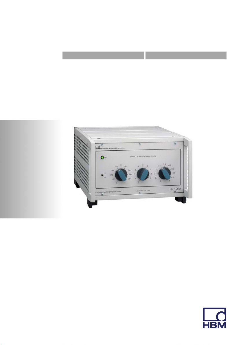
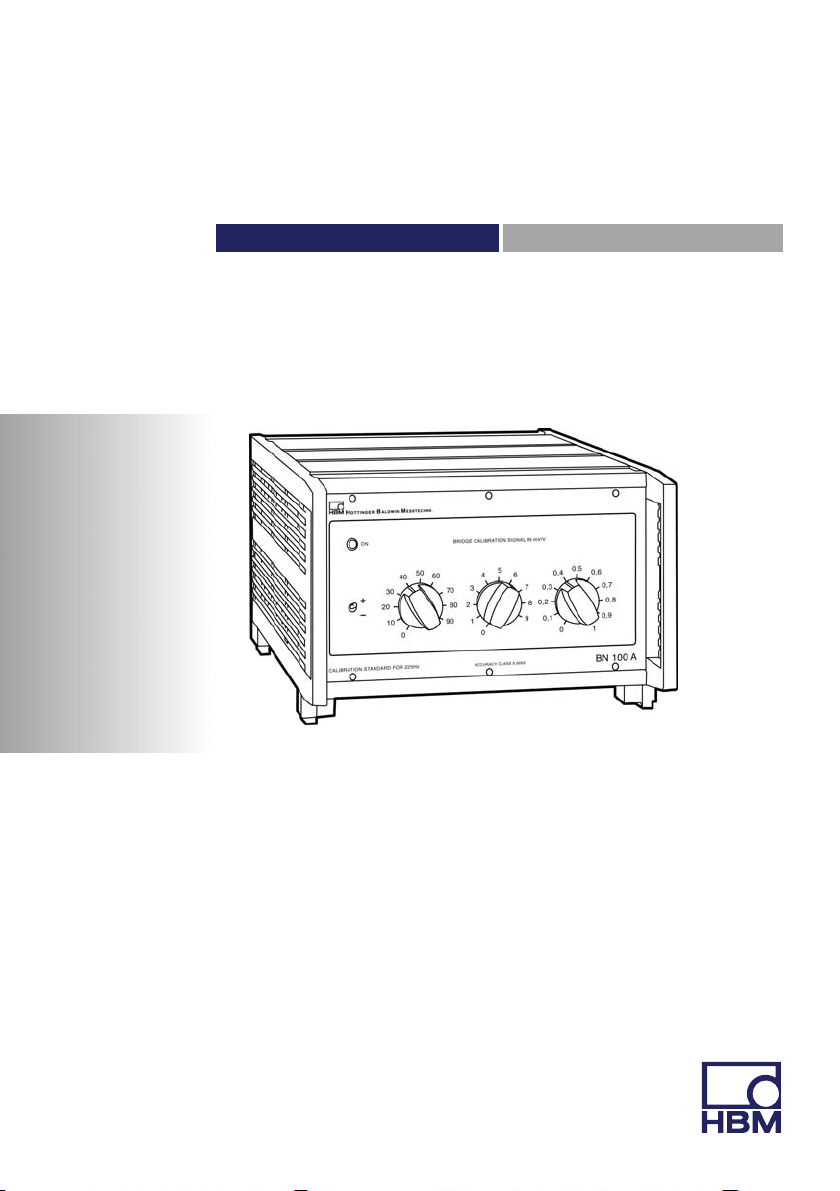
HBM BN100A User manual

Operating Manual | Bedienungsanleitung
English Deutsch
BN100A

Hottinger Baldwin Messtechnik GmbH
Im Tiefen See 45
D-64239 Darmstadt
Tel. +49 6151 803-0
Fax +49 6151 803-9100
www.hbm.com
Mat.: 7-2002.0083
DVS: A0643-6.1 HBM: public
05.2017
EHottinger Baldwin Messtechnik GmbH.
Subject to modifications.
All product descriptions are for general information only.
They are not to be understood as a guarantee of quality or
durability.
Änderungen vorbehalten.
Alle Angaben beschreiben unsere Produkte in allgemeiner
Form. Sie stellen keine Beschaffenheits- oder Haltbarkeits
garantie dar.

Operating Manual | Bedienungsanleitung
English Deutsch
BN100A

2A0643-6.1 HBM: public BN100A
English
1 Safety instructions 3........................................
2 Introduction 8..............................................
2.1 List of components and accessories supplied 8..................
2.2 General 8...................................................
3 Connection 10...............................................
4 Calibration 13...............................................
4.1 Calibration of a measuring chain 13.............................
5 Specifications 15............................................

Safety instructions
BN100A A0643-6.1 HBM: public 3
1 Safety instructions
Use in accordance with the regulations
The BN100A may be connected - instead of a strain
gauge‐based transducer and for the purpose of calibra
tion - only to measuring devices that work with a carrier
frequency of 225 Hz.
Use for any additional purpose shall be deemed to be not
in accordance with the regulations.
In the interests of safety, the instrument should only be
used as described in the Operating Manual. It is also es
sential to observe the appropriate legal and safety regula
tions for the application concerned during use. The same
applies to the use of accessories.
General dangers of failing to follow the safety in
structions
The BN100A corresponds to the state of the art and is
safe to operate. The instrument can give rise to residual
dangers if it is inappropriately installed and operated by
untrained personnel.
Everyone involved with the installation, commissioning or
maintenance of the instrument must have read and un
derstood the Operating Manual and in particular the tech
nical safety instructions.
Conditions on site
Protect the device from direct contact with water (IP20).
It is safe to operate the unit up to an altitude of 2000 m.

Safety instructions
4A0643-6.1 HBM: public BN100A
Install the BN100A so that it can be disconnected from
the mains at any time without difficulty. Make sure that
the mains plug is accessible.
Maintenance and cleaning
The BN100A module is maintenance‐free. Please note
the following points when cleaning the housing:
- Before cleaning, disconnect the devices from the power
supply.
- Clean the housing with a soft, slightly damp (not wet!)
cloth. You should never use solvent, since this could
damage the labelling on the front panel and the display.
- When cleaning, ensure that no liquid gets into the
device or connections.
Residual dangers
The scope of supply and list of components provided with
the BN100A cover only part of the scope of measurement
technology. In addition, equipment planners, installers
and operators should plan, implement and respond to the
safety engineering considerations of measurement tech
nology in such a way as to minimise residual dangers.
Prevailing regulations must be complied with at all times.
There must be reference to the residual dangers connec
ted with measurement technology.
Any risk of residual dangers when working with the
BN100A is pointed out in this manual by means of the
following symbols:

Safety instructions
BN100A A0643-6.1 HBM: public 5
WARNING
Type of danger
Consequences of non-compliance
Averting the danger
SWarning sign:
draws your attention to the danger
SSignal word:
indicates the severity of the danger (see table below)
SType of danger:
mentions the type or source of the danger
SConsequences:
describes the consequences of non-compliance
SDefense:
indicates how the danger can be avoided/bypassed
Danger class according to ANSI
Warning sign, signal word Significance
WARNING This marking warns of a potentially dangerous
situation in which failure to comply with safety
requirements can result in death or serious physical
injury.

Safety instructions
6A0643-6.1 HBM: public BN100A
CAUTION This marking warns of a potentially dangerous
situation in which failure to comply with safety
requirements can result in slight or moderate physical
injury.
Note This marking draws your attention to a situation in
which failure to comply with safety requirements
could lead to damage to property.
On the module
Meaning: Take details in the operating manual into
account
Meaning: CE mark
The CE mark enables the manufacturer to guarantee that
the product complies with the requirements of the relev
ant EC guidelines (the declaration of conformity is avail
able at http://www.hbm.com/HBMdoc).
Working safely
Error messages should only be acknowledged if the
cause of the error is removed and no further danger ex
ists.
The instrument complies with the safety requirements of
DIN EN 61010, Part 1 (VDE 0411, Part 1); Protection
Class I.
To ensure adequate immunity from interference, use only
Greenline shielded ducting (see HBM offprint ”Greenline
shielding design, EMC‐compliant measuring cable;
G36.35.0).

Safety instructions
BN100A A0643-6.1 HBM: public 7
Conversions and modifications
The BN100A module must not be modified from the
design or safety engineering point of view except with our
express agreement. Any modification shall exclude all
liability on our part for any damage resulting therefrom.
In particular, any repair or soldering work on mother
boards is prohibited. When exchanging any modules,
only original HBM parts must be used. Repairs to the unit
may only be carried out by HBM.
Qualified personnel
This instrument is only to be installed and used by quali
fied personnel strictly in accordance with the specifica
tions and with the safety rules and regulations which fol
low. It is also essential to comply with the appropriate
legal and safety regulations for the application concerned
during use. The same applies to the use of accessories.
Qualified personnel means persons entrusted with the
installation, assembly, commissioning and operation of
the product who possess the appropriate qualifications
for their function.
Maintenance and repair work on an open device with the
power on must only be carried out by trained personnel
who are aware of the dangers involved.


Introduction
8A0643-6.1 HBM: public BN100A
2 Introduction
2.1 List of components and accessories
supplied
Lists of components supplied:
S1 BN100A
S1 operating manual BN100A
The bridge calibration unit BN100A is only available in
conjunction with a DKD calibration certificate for voltage
ratio (2 mV/V calibration range, 5 V excitation voltage).
This calibration is not included in the scope of supply.
Order‐no.: K-CAL_VD or
K-CAL-VZ
Accessories:
S1 connection cable
from Version 2.00: Kab 0238B-3, 3m long
otherwise: Kab 0238A-3, 3m long
S1 connection cable Kab 133A
S1 mains cable
Notice
The mains cable included in the scope of supply is a
connection cable with 3 x 0.75 mm2copper cross-sec
tion.
The mains cable may only be exchanged for a cable of
the same type.

Introduction
BN100A A0643-6.1 HBM: public 9
2.2 General
The BN100A bridge calibration unit is a highly precise
calibrator to calibrate measuring equipment and meas
urement chains which function with a carrier frequency of
225Hz. In the first instance the BN100A is intended for
the calibration of the DMP40/DMP41 digital precision in
struments. The BN100A bridge calibration unit is inserted
in the measuring system to be calibrated in place of the
transducer (full bridge), or is connected directly with the
measuring instrument, and simulates with the aid of
switchable inductive dividers the output signals of the
transducer in a range of "100mV/V. The unique preci
sion of the simulation of the transducer signals is effected
by a control circuit which additionally reduces the low er
ror of the inductive divider stages of a large degree. The
full accuracy of the BN100A only comes into effect when
it is connected in the six‐wire‐circuit. The calibration error
will then be max. 5ppm with a signal of 2mV/V.
Fig. 2.1 Block circuit diagram

Connection
10 A0643-6.1 HBM: public BN100A
3 Connection
WARNING
Comply with the safety instructions before putting
the instrument into service.
The power pack has been designed for 230V connection.
If you have to connect the BN100A to a mains voltage
differing from 230V, the device can be switched to 115V
mains voltage (voltage‐selection switch).
Set voltage‐selection switch to 115V mains voltage:
SUse screwdriver to squeeze out fuse carrier
STurn fuse carrier by 180o
SReinsert fuse carrier (115V label visible)
Turn by 180o
230V 115V
Housing earth
Mains connection
Fig. 3.1 Switching the mains voltage

Connection
BN100A A0643-6.1 HBM: public 11
Microfuse replacement after blowing:
SUse screwdriver to squeeze out fuse carrier
SReplace fuses
SReinsert fuse carrier
CAUTION
Be sure to have selected the appropriate mains voltage
connection
230V: 0,2AT fuse 115V: 0,4AT fuse
The bridge calibration unit is connected to the measuring
chain in place of the transducer with the socket Bu1.
A:Measuring signal (+) white
B:Bridge excitation voltage (-) black
C:Bridge excitation voltage( +) blue
D:Measuring signal (-) red
E:Three inner cable shields (measurement ground)
F:Sensor circuit (+) green
G:Sensor circuit (-) grey
AF
BG E
CD
Fuses:
230 VAC 2 x 0,2 A sl
115 VAC 2 x 0,4 A sl
Connector housing: Outer cable shield (ground potential)
Fig. 3.2 Socket assignment

Connection
12 A0643-6.1 HBM: public BN100A
The contact allocation of the socket Bu1 corresponds to
the standard of HBM transducers. In order to calibrate
with the six‐wire circuit the bridge excitation voltage con
tacts of the BN100A are already bridged with the sensor
circuits G and F. Due to the fact that the DMP40 or the
DMP41 resp. regulates the excitation voltage, the cable
and contact resistances will have no influence on the cal
ibration.
Calibration in six‐wire circuit is, however, only sensible if
the measurements are made also in the six‐wire circuit.
The PE connection on the rear enables additional metal
parts (e.g. metal table) to be integrated in the protection
concept.

Calibration
BN100A A0643-6.1 HBM: public 13
4 Calibration
4.1 Calibration of a measuring chain
Calibration of the DMP40 / DMP41 and ML38
SBe sure to have selected the appropriate mains
voltage (see Fig. 3.1).
SConnect the bridge calibration unit to the DMP/ML38
in place of the transducer1). Do not disconnect any
extension cable.
SSwitch on the bridge calibration unit and calibrate the
DMP/ML38 (see operating manual DMP/ML38).
Notice
Due to the electronic control feature of the divider stages,
the output noise voltage of the BN100A is greater than
that of a transducer. However, this will only be noticed if
signals of 2mV/V are resolved by the DMP40 or the
DMP41 at 1 000 000d. In such cases it is recommended
to set the filter of the DMP to “0.2Hz Bessel”.
Calibration of an amplifier
SIn place of the full bridge transducer1) connect the
BN100A calibration unit to the amplifier by means of
the connection cable supplied with the calibrator. Do
not disconnected any extension cable.
1) HBM transducers are balanced to the nominal sensitivity given on their identification plate,
including the permanently mounted connection cable.

Calibration
14 A0643-6.1 HBM: public BN100A
SSwitch the bridge unbalance at the BN100A to 0mV/V.
Switch on the amplifier and the calibrator. Zero bal
ance the amplifier with its subsequent instruments.
SPreselect the required polarity of the calibration signal
with the polarity selector switch on the front panel.
Polarity selector switch
SSet the bridge detuning and calibrate the amplifier ac
cording to its operating manual.
On principle the amplifier should be calibrated in the
range intended for the actual measurement. If ranges are
switched during the measurements the step error should
be considered (see specifications).

Specifications
BN100A A0643-6.1 HBM: public 15
5 Specifications
Type BN100A
Accuracy class 0.0005
Supply voltage VAC voltage 230, 50 Hz
AC voltage 115, 60 Hz
Degree of pollution,
max. altitude for operation m
2
2000
Overvoltage category II
Power consumption VA 20
Calibration signal mV/V -100...+100
Steps mV/V 0. 1
Calibration error1) related to 2 mV/V %t0.0005
Step error, related to the specific step
value
% 0.0003
Calibration signal deviation on chan
ging polarity, related to 2 mV/V
% 0.0004
Output noise voltage in permissible
frequency range
nV/ǨHz t20
Nominal temperature range oC +15...+30
Permissible ambient temperature
range
oC 0...+50
Storage temperature range oC -20...+60
Nominal value of the bridge excita
tion voltage (rms value)
V 10
Permissible bridge excitation
voltage2) (rms value)
V 1...15
1) Related to socket Bu1 of the BN100A, with the measuring instrument connected in a 6-wire
circuit.
2) Traceable to PTB; typically at 2.5 V, 5 V and 10 V

Specifications
16 A0643-6.1 HBM: public BN100A
Nominal frequency of the bridge ex
citation voltage
Hz 225"2
Permissible frequency of the bridge
excitation voltage
Hz 225"10
Input resistance 350"4
Output resistance 350"4
Dimensions (w x h x d) mm 255 x 171 x 367
Degree of protection IP20 per EN60529
Weight kg 7.2
Maximum relative humidity for tem
peratures up to 31 oC
Linearly decreasing rel. humidity at 40
°C up to
%
%
80
50
The bridge calibration unit BN100A is only available in
conjunction with a DKD calibration certificate for voltage
ratio (2 mV/V calibration range, 5 V excitation voltage).
This calibration is not included in the scope of supply.
Order‐no.: K-CAL_VD or
K-CAL-VZ

Bedienungsanleitung | Operating manual
English Deutsch
BN100A
Table of contents
Languages:
Other HBM Transducer manuals
Popular Transducer manuals by other brands

FLIR
FLIR Raymarine CPT-S Installation sheet

FASTRON.
FASTRON. FWBV412H29 user manual

Navman
Navman THROUGH HULL AND IN-HULL installation manual

Beko
Beko METPOINT PRM SP11 Instructions for installation and operation

Veris Industries
Veris Industries EP3 Series installation guide

M-system
M-system L3CK instruction manual