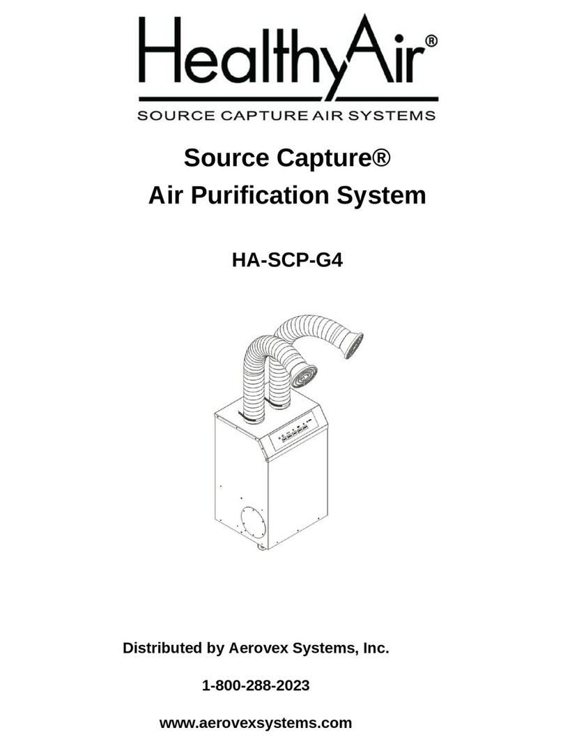
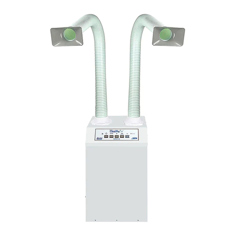
HealthyAir HA-CMP-G2-W User manual

Ceiling-Mount Air Cleaner
HA-CMP-G2-W
Owner’s Manual
1
2
3
4
5
6-14
15
16
17-18
19-23
24
25-28
29
Table of Contents
HealthyAir® Series 1219-CM Filters
Important Safety Instructions
Technical Specifications
Packaging Reference
Component Reference
Installation Instructions
Electrical Wiring Instructions
Electrical Wiring Schematic
Operation Guidelines
Filter Replacement
Maintenance
Basic Service and Troubleshooting
1-Yeart Limited Warranty
Product Registration Form
30
Healthy Air Inc.
800-259-2535
www.HealthyAir.com

1
HealthyAir®HA-CMP-G2-W
Ceiling-Mount Air Cleaner
with
HealthyAir®Series 1219-CM
Filters
at
www.HealthyAir.com

2
WARNING
Cut power to the unit before servicing or replacing filters. Failure to
do so could result in serious personal injury and death.
I. Important Safety Instructions
Read the Owner's Manual and Important Safety Instructions carefully. Failure to
follow these instructions could cause a malfunction of the filter or unsatisfactory
performance. Follow a regular service and maintenance schedule for efficient
operation.
To reduce the risk of electric shock, fires, and/or injury:
•Do not use the air purifier in wet or damp locations
•Do not use outdoors
•Do not use at ambient temperature of above 95°F/35°C
•Do not use fabrics or other material to cover the inlet and outlet of the unit
•Do not allow children to operate or play with the unit
For safety reasons and to prevent electric shock, cut power to the unit under the
following conditions:
•When not in use for a long period of time
•When cleaning, servicing the machine or during replacement of filters
•When moving the air purifier
To prevent electric shock, do not dismantle, repair or modify this product.
Maintenance and cleaning instructions should be followed exactly as directed in
this manual. In case of malfunction, please contact an authorized distributor or
Healthy Air Inc. for service instructions.
To reduce the risk of electric shock, the unit has grounding type wiring that has a
third (grounding) wire. The unit must be hard wired and all wiring must comply
with applicable electrical codes and ordinances. Do not alter the wiring.

3
II. Technical Specifications
Model Number
HA-CMP-G2-W
Rated Voltage
120V/60HZ
Power Consumption
200W
Weight
65 lbs. (29.5 kg)
Base Dimensions
24x24x15.4 in. (600×600×392 mm)
Air Flow Rate
550 cfm (930 m3/h)
Noise Level
56 dB

4
III. Packaging Reference
The Ceiling-Mount Air Cleaner is shipped in one (1) carton, that contains
the following:
•(1) Air Purification Unit
•(3) Filters
•(4) Eye Bolts
•(1) Remote Control
•(1) Manual
Note: The Ceiling-Mount Air Cleaner is to be hard wired and does not have a
power cord.

5
IV. Component Reference
11. Eye Bolt
12. Capacitor
13. HV PCB
14. PCB Board
15. Wiring Box
16. Safety Switch
17. Fuse
18. Control Panel
19. Control Panel Display
20. Remote Control
1. Face Plate
2. Pre-Filter
3. eGrid
4. eHEPA®Filter
5. Activated Carbon Filter
6. Fan Coil
7. Blower/Motor
8. HV Contact Spring
9. Outside Vent Outlet Port
10. Main Box

6
V. Installation Instructions
5.1 Installation of Eye Bolts
5.1.1 Carefully place the unit face down, as shown in Fig. 1.
5.1.2 Screw the four (4) Eye Bolts into the respective rivet nuts, located at the
four corners of the Bottom Plate.
5.1.3 Ensure that each Eye Bolt is fully and securely installed.
Fig. (1) –Installing Eye Bolts
Eye Bolt
Face Plate
Bottom Plate

7
V. Installation Instructions
5.2 Optimal Unit Location
The standard HealthyAir®Ceiling Mount Air Purification System recirculates air
back into the facility, after it is purified in a 3-stage filtration process.
Note: Locate and install the unit such that it can be easily accessed and
opened for periodic filter replacement. Refer to Section 9.2 for details.
5.2.1 It is best to install the unit in the center of the room, so that contaminated
air is drawn into the bottom of the unit and clean air is evenly
discharged from the sides. This dynamic creates a circular flow pattern,
referred to as Coanda Flow, as shown in Fig. 2.
Fig. (2) –Coanda Flow Pattern
5.2.2 The unit is designed to be installed in place of a standard 2'x2’ ceiling tile,
and it must be securely attached to the building structure for adequate
support.
5.2.3 Depending on the type of building structure, whether the ceiling has an
I-Beam or concrete construction, follow the appropriate protocol for
proper installation and support of the unit.

8
V. Installation Instructions
5.3 Mounting to I-Beam Ceiling Structure
Using Fig. 3 as a guide, install the HealthyAir®Ceiling Mount Air Purification
System in accordance with all applicable building and mechanical codes.
Fig. (3) –Mounting Unit to I-Beam Ceiling
5.4 Mounting to Concrete Ceiling Structure
Using Fig. 3 as a guide, install the HealthyAir®Ceiling Mount Air Purification
System in accordance with all applicable building and mechanical codes.
Fig. (4) –Mounting Unit to Concrete Ceiling
I-Beam
12 Gauge
Wire Rope
M6 Nut
Concrete Ceiling
Expansion Tube
Suspended Ceiling
Eye Bolt
Suspended Ceiling
M6 Nut
M6 Expansion Screw
& M6 Screw

9
V. Installation Instructions
5.5 Outside Vent Application
The HealthyAir®Ceiling Mount Air Purification Outside Vent System is designed
to enable filtered air to be discharged from the facility via exhaust ducting.
The unit is equipped with two (2) 4”x10” Outside Vent Outlet Ports and (2)
Outlet Port Cover Plates, that allow the exhaust duct to either be connected to
the right or left side of the unit depending on which configuration is preferred.
5.5.1 Determine the ideal exhaust duct configuration given the arrangement of
the facility.
5.5.2 Remove the Outlet Port Cover Plate, from the corresponding Outside
Vent Outlet Port, by unscrewing the eight (8) screws, shown in Fig. 5.
Fig. (5) –Outside Vent Outlet Port and Cover Plate
Outlet Port
Cover Plate
Outside Vent
Outlet Port

10
V. Installation Instructions
5.5 Outside Vent Application
5.5.3 Install the HealthyAir®Ceiling Mount Air Purification
System in accordance with the instructions provided in Sections 5.1-5.4
herein.
5.5.4 Connect a universal 4’’x10” to 6” Ø Transition (not supplied) to the
Outside Vent Outlet Port and ensure that the junction is secure.
5.5.5 Connect a 6” Ø Exhaust Duct (not supplied) to the Transition and
ensure that the junction is secure.
5.5.6 Run the Exhaust Duct out of the facility per applicable IMC codes.
Fig. (6) –Outside Vent Transition and Exhaust Ducting
Exhaust Duct
Transition

11
V. Installation Instructions
5.6 Converting Recirculating Vent to Outside Vent (Optional)
The HealthyAir®Ceiling Mount Air Purification Recirculating Vent System can
be converted to a HealthyAir®Ceiling Mount Air Purification Outside Vent
System by installing Outlet Vent Cover Plates on the back of the Face Plate.
Conversely, the HealthyAir®Ceiling Mount Air Purification Outside Vent System
can be converted to a HealthyAir®Ceiling Mount Air Purification Recirculating
Vent System by removing the Outlet Vent Cover Plates from the back of the
Face Plate.
Fig. (7) –Recirculating Vent and Outside Vent Face Plates
5.6.1 Unscrew and remove the two (2) Thumb Screws at the base of the Face
Plate, as shown in Fig. 8.
5.6.2 Open the Face Plate and swing it open about 90° to access the back
side of the Face Plate, as shown in Fig. 8.
5.6.3 There are two (2) Outlet Vents on the Face Plate. On the back side of
the Face Plate, each Outlet Vent has four (4) Threaded Studs. Locate
the eight (8) Threaded Studs on the back of the Face Plate, as shown
in Fig. 9.
Recirculating Vent Face Plate
Outside Vent Face Plate

12
V. Installation Instructions
5.6 Converting Recirculating Vent to Outside Vent (Optional)
Fig. (8) –Opening Face Plate
5.6.4 Locate and remove the eight (8) Hex Nuts that are preinstalled on the
back of the Face Plate, as shown in Fig. 9.
Fig. (9) –Back Side of Face Plate
Thumb
Screws
Outlet Vent
Threaded Studs
w/ Hex Nuts
Recirculating Vent
Face Plate

13
V. Installation Instructions
5.6 Converting Recirculating Unit to Outside Vent (Optional)
5.6.5 Locate the two (2) Outlet Vent Cover Plates, shown in Fig. 10.
Fig. (10) –Outlet Vent Cover Plates
5.6.6 Install the Outlet Vent Cover Plates on the Face Plate Outlet Vents, as
shown in Figs. 10 and 11.
Fig. (11) –Installation of Outlet Vent Cover Plates on Face Plate
Outlet Vent
Cover Plate
Hex Nut

14
V. Installation Instructions
5.6 Converting Recirculating Unit to Outside Vent (Optional)
5.6.7 Reinstall the eight (8) Hex Nuts to secure the Outlet Vent Cover Plates
on the Face Plate.
5.6.8 Close the Face Plate and reinstall the two (2) Thumb Screws, as
shown in Fig. 12.
Fig. (12) –Securing Outside Vent Face Plate
Thumb
Screws
Outside Vent
Face Plate

15
VI. Electrical Wiring Instructions
Note: The HealthyAir®Ceiling Mount Air Purification system must be hard wired
when recess mounted. All wiring must comply with applicable electrical codes
and ordinances.
6.1 Instructions to Hard Wire 120V AC, 60 Hz
6.1.1 Install a 15 Amp external circuit breaker to bring power to the unit.
6.1.2 Run three (3) No. 14 Color-Coded Wires through the conduit to the
Wiring Box of the unit, as shown in Fig. 13.
6.1.3 Attach the Green wire to the external Ground. Note that, the Black wire
and White wire are the power carries.
6.1.4 Attach the conduit to the knockout.
6.1.5 Attach the Green ground wire to the ground screw and to the terminal
marked G in the Wiring Box. Ground the unit for proper operation and
safety.
6.1.6 Attach the Black wire to the terminal marked L and the White wire to the
terminal marked N in the Wiring Box, as shown in Fig. 13.
Fig. (13) –Electrical Wiring Diagram

16
VII. Electrical Wiring Schematic
Fig. (14) –Electrical Wiring Schematic

17
VIII. Operation Guidelines
8.1 Power Supply and Activation
The input power to the unit should include an external circuit breaker with a
minimum 15 Amp current rating.
8.1.1 Provide power to the unit by turning the circuit breaker to the ON
position.
Once the circuit breaker is on, the Power indicator light [ ], on the
Control Panel, will turn on and display a red light.
8.1.2 Activate the unit by pressing the Power button located on the Control
Panel, shown in Fig. 15, or on the Remote Control.
Once the unit is powered, the motor will start with the Fan Speed set to
the Mid-Speed and the eHEPA®indicator will light up and display a
green light, which indicates that the eHEPA®system is activate.
8.2 System Controls
Each of the respective control elements shown on the Control Panel Display in
Fig. 15 work as follows:
•SPEED button, on the Control Panel and Remote Control, adjusts the
volume of airflow being taken in through the hood. Airflow speed can be
adjusted to one of three settings: Low –Mid –High Speed.
•eHEPA button, on the Control Panel and Remote Control, turns the
eGrid on and off. When the eGrid is powered the symbol above the
eHEPA button, as well as the eGrid Active light, will turn green.
Pressing the eHEPA button once more will shut off the eGrid and turn
off the indicator light.
•TIMER button, on the Control Panel and Remote Control, is for
operation of the timing clock. When this feature is in use the unit will
automatically shut off after the set time expires. The system’s default
timing is 4 hours of operation.

18
VIII. Operation Guidelines
8.2 System Controls
•TIMER
To set the timer manually, press the TIMER button once for every hour
you wish to run the machine (i.e. press TIMER once for 1-hour of run
time, press TIMER twice for 2-hours of run time, press TIMER three
times for 3-hours of run time, and press TIMER four times for 4-hours of
run time).
If the TIMER button is pressed five (5) times, such that it passes
through the complete timing schedule, it will run continuously until the
unit is manually turned off.
•eGrid Active indicator light, on the Control Panel, indicates the status
of the eHEPA® and eGrid system. When the eGrid Active indicator light
is on, while the eHEPA button is on, the eGrid is functioning properly. If
the eGrid Active indicator light is off, while the eHEPA button is on, it
signals that the eGrid is malfunctioning and the unit requires service.
•LIGHT button, on the Control Panel and Remote Control, is inactive.
Note that, LED lighting is an optional feature only on HealthyAir®
Ceiling Mount Source Capture®Air Purification Systems.
Fig. (15) - Control Panel Display

19
IX. Filter Replacement
9.1 Replacement Filter
The HealthyAir®Ceiling Mount Air Purification System (HA-CMP-G2) utilizes
the HealthyAir®Series 1219 Replacement Filters, as follows:
•HealthyAir®Pre-Filter
Model No. HA-PF-1219
•HealthyAir®eHEPA® Filter
Model No. HA-EH-1219
•HealthyAir®Activated Carbon Filter
Model No. HA-CC-1219
Note that, only manufacturer supplied HealthyAir®Replacement Filters are
compatible with HealthyAir®Ceiling Mount Air Purification Systems. No other
replacement filters are to be used with this unit. The improper use of
non-manufacturer supplied filters will void any potential warranty claim.
9.2 Filter Change
When the unit has been in operation for 400-hours, the Filter Change indicator
light, on the Control Panel, will begin to flash indicating that the filters must be
replaced, as follows:
Note: Depending on usage and contaminates in the environment, the filter
may need to be replaced before the 400-hour default cycle expires. Contact a
representative to determine if you need to replace the filter more frequently.
9.2.1 Turn the unit Power Off and cut the power supply to the unit by setting
the external circuit breaker to the Off position.
9.2.2 Unscrew and remove the two (2) Thumb Screws on the Face Plate, to
allow the Face Plate to swing open, as shown in shown in Fig. 16.
Caution: Take care when opening the Face Plate to ensure that the
hinge remains engaged, so that the Face Plates does not fall off.
Table of contents
Other HealthyAir Air Cleaner manuals

HealthyAir
HealthyAir HA-PAP-G3 User manual

HealthyAir
HealthyAir HA-SSC-G4 User manual

HealthyAir
HealthyAir HA-SCP-G5-AE User manual

HealthyAir
HealthyAir HA-CMP-G2-R User manual

HealthyAir
HealthyAir Source Capture HA-SCP-G4-W User manual

HealthyAir
HealthyAir Source Capture HA-SCP-G4 User manual

HealthyAir
HealthyAir HA-PAP-G2 User manual

HealthyAir
HealthyAir Source Capture HA-SCP-G4-WS-R User manual

HealthyAir
HealthyAir HA-CMSC-G3-W User manual

HealthyAir
HealthyAir HA-SSC-G5 User manual