HealthyAir Source Capture HA-SCE-G2 User manual

Source Capture®
Fan-Filter Exhauster
HA-SCE-G2
Distributed by Aerovex Systems, Inc.
1-800-288-2023
www.aerovexsystems.com

Table of Contents
HealthyAir® Model Numbers – Unit & Filter
1
Important Safety Instructions
2
Technical Specifications
3
Packaging Reference
4
Unpacking Notice
5
Component Reference
6
Assembly Instructions - Outside Ventilation
7-9
Assembly Instructions – Recirculating Ventilation
10
Assembly Instructions – Inlet Ports/Hose/LED
11-16
Operation Guidelines
17-18
Filter Replacement
19-21
Maintenance
22
Basic Service and Troubleshooting
23-27
Electrical Wiring Schematic
28
1-Yeart Limited Warranty
29
Product Registration Form
30
Distributed by Aerovex Systems, Inc.
1-800-288-2023
www.aerovexsystems.com

1
HealthyAir®
Source Capture®Fan-Filter Exhauster
HA-SCE-G2
Recirculating Ventilation Outside Ventilation
Filter Model No. HA-IFM-1111
www.aerovexsystems.com

2
WARNING
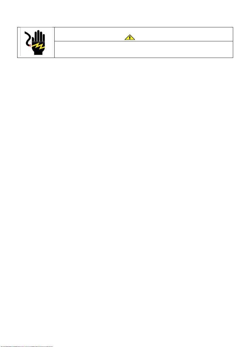
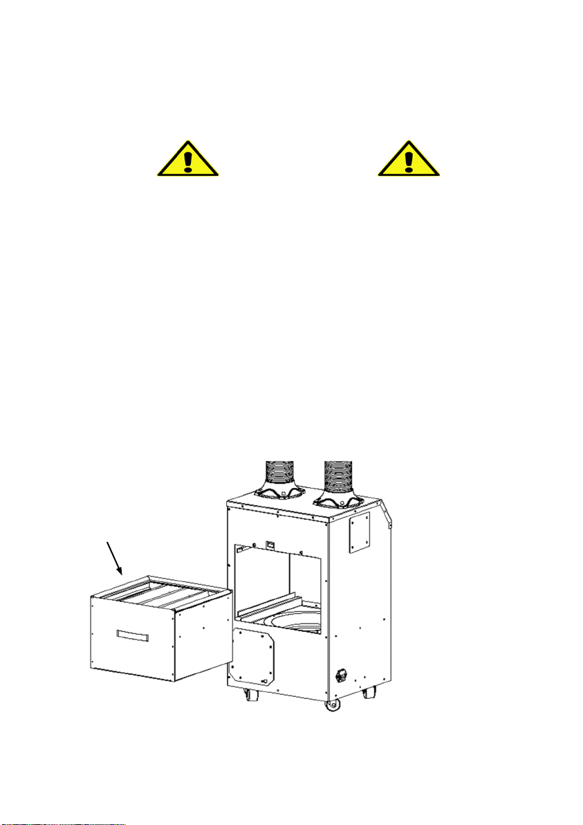
Unplug the power cord before servicing or replacing filters. Failure
to do so could result in serious personal injury and death.
I. Important Safety Instructions
Read the Owner's Manual and Important Safety Instructions carefully. Failure to
follow these instructions could cause a malfunction of the unit.
It is advised that a surge protector device with a minimum rating of 1,000 Joules
is used to protect the HealthyAir®unit from damage by AC power transients or
lightening surges.
To reduce the risk of electric shock, fires, and/or injury:
•Do not use the unit in wet or damp locations
•Do not use outdoors
•Do not use at ambient temperature of above 95°F/35°C
•Do not use fabrics or other material to cover the inlet and outlet of the unit
•Do not allow children to operate or play with the unit
For safety reasons and to prevent electric shock, unplug the power cord from the
electric outlet socket under the following conditions:
•When not in use for a long period of time
•When cleaning, servicing, moving, or replacing filters
To prevent electric shock, do not dismantle, repair or modify this product.
Maintenance and cleaning instructions should be followed exactly as directed in
this manual. In case of malfunction, please contact an authorized distributor or
Healthy Air Inc. for service instructions.
To reduce the risk of electric shock, the equipment has a grounding type plug
that has a third (grounding) pin. This plug will only fit into a grounding type power
outlet. If the plug does not fit into the outlet, contact qualified personnel to install
the proper outlet. Do not alter the plug in any way.
To reduce the risk of electric shock, do not pull the cord to remove the plug from
its outlets. Protect the cord against heat, oil and sharp objects. Do not run any
appliance over the cord. Do not pull or carry by the cord, use cord as a handle,
close a door on the cord, or pull cord around sharp edges or corners.

3
II. Technical Specifications
Model Number HA-SCE-G2-W/B/G
Rated Voltage 120V/60HZ
Power Consumption 200W
Weight 40 lbs. (18 kg)
Base Dimensions 14x12x24 in. (350×310×615 mm)
Hose Length
(Standard) 48 in (122 cm)
Air Flow Total
Air Flow/Inlet (Avg.)
470 cfm (800 m3/h)
118 cfm (200 m3/h)
Sound Level 54 dB

4
III. Packaging Reference
The Source Capture®Fan-Filter Exhauster is shipped in two (2) cartons, as
follows:
Carton 1: (1) Fan-Filter Exhauster Unit, (1) Fan-Filter Module, (4) Wheel
Casters, (2) Inlet Flange, (1) Outlet Flange, (1) Acoustic Mat,
(1) Remote Control, (1) Power Cord, (1) Screwdriver
Carton 2: (2-4) Extraction Hose w/ Hood, (2-4) LED Grille + LED Cable +
LED Bulb (Optional), (1-2) Inlet Tube (Optional)

5
IV. Unpacking Notice
NOTICE
Before operating the machine, do the following:
1. Open the Access Door (Refer to Section 7.2)
2. Remove the Integrated Filter Module (HA-FFM-1111)
3. Remove the plastic wrapping from the filter!
4. Re-install the Integrated Filter Module
5. Replace and secure the Access Door
Remove plastic wrapping
from Fan-Filter Module
prior to use!

6
IV. Component Reference
1. Outer Frame
2. Acoustic Mat
3. Blower/Motor
4. Metal Screen
5. Caster Wheels
6.BasePlate
7. Motor Mount Plate
8. Baffle Plate
9. Guide Ring
10. Safety Screen
11.Fan-Filter Module
12.Inlet Port
13.Safety Switch
14.Capacitor
15. PCB Board
16. Extraction Hose
17. LED Bulb (Option)
18.Hood
19.G4 Mount (Option)
20.LED Grille (Option)
21. LED Cable Plug (Option)
22.LED Cable Socket
23.Top Cover
24. Control Panel Display
25.Control Display Board
26.Thumb Screw
27.Access Door
28.Power Cord
29.Remote Control
30. Base Blank-Off Plate
31. Outlet Flange

7
V. Assembly Instructions
5.1 Outside Ventilation Configuration
The HealthyAir® HA-SCE-G2 may be configured for Outside Ventilation,
to connect the outlet to ducting to exhaust filtered air out of the facility.
For Recirculating Ventilation use, in which filtered air is discharged from
the bottom of the unit and recirculated back into the facility skip Section
5.1 and refer to the installation instructions in Section 5.2.
For Outside Ventilation configuration, the unit comes with one (1) Outlet
Flange and one (1) Base Blank-Off Plate, as shown in Fig. 1.
Fig. (1) –Outside Ventilation Configuration
The HealthyAir® HA-SCE-G2 unit has two Outside Vent Outlet Ports, one
located on the back panel, and one located on the side panel, as shown in
Fig. 2. Each Outlet Port is equipped with an Outlet Port Cover Plate.
Either Outlet Port may be used for outside venting, depending on which
configuration is more suitable for connection to exhaust ducting.
Outlet Port
Base Blank-Off Plate
Outlet Flange
Outlet Port
Cover Plate

8
V. Assembly Instructions
5.1 Outside Ventilation Configuration
Fig. (2) – Outside Vent Outlet Ports
5.1.1 Remove the (16) Mounting Screws that are preinstalled on the Base
Plate.
5.1.2 Position the Base Blank-Off Plate over the Base Plate.
5.1.3 Ensure that the bolt pattern for the Caster Wheels on the Base Blank-
Off Plate aligns with the bolt pattern on the Base Plate.
5.1.4 Reinstall the (16) Mounting Screws to secure Base Blank-Off Plate.
Note, for outside ventilation application the unit may also be setup
with the Caster Wheels installed on the Base Blank-Off Plate.
In this case, position the Base Blank-Off Plate, place the Caster
Wheels over the plate and reinstall the Mounting Screws to secure
the Blank-Off Plate and Wheels.
Outside Vent
Outlet Port
w/
Cover Plate
(Side Panel)
Outside Vent
Outlet Port w/
Cover Plate
(Back Panel)

9
V. Assembly Instructions
5.1 Outside Ventilation Configuration
5.1.5 Determine which Outlet Port (back panel or side panel) will be
used for connection to exhaust ducting, and then remove the
Outlet Port Cover Plate to open the Outlet Port.
5.1.6 Install the Outlet Flange on the Outlet Port, as shown in Fig.3.
5.1.7 Connect a 5’’ diameter Exhaust Duct or Pipe (not supplied) to
the Outlet Flange and ensure that the connection is secure
with an airtight seal.
5.1.8 Run the Exhaust Duct/Pipe out of the facility per applicable
mechanical codes.
Fig. (3) – Outlet Flange Installation
Outlet Port w/
Outlet Flange
Outlet Port w/
Cover Plate
Outlet Port w/
Cover Plate

10
V. Assembly Instructions
5.2 Recirculating Ventilation Configuration
When the unit is setup for Recirculating Ventilation, particles are collected
by the unit and filtered air is discharged from the bottom of the unit and
recirculated within the facility.
5.2.1 Place the unit on its side on a flat surface, as shown in Fig. 4.
5.2.2 Locate the four (4) Caster Wheels and the screwdriver that are
provided in Carton 1.
5.2.3 Unscrew and remove the Mounting Screws that are pre-mounted on
the Base Plate, on the bottom of the unit. There are four (4) screws
per wheel, for a total of sixteen (16) Mounting Screws.
5.2.4 Align the bolt holes of the Caster Wheels with the bolt holes on the
Base Plate and use four (4) Mounting Screws to secure each Caster
Wheel to the Base Plate.
Fig. (4) – Caster Wheel Installation
Base Plate
(16) Mounting Screws

11
V. Assembly Instructions
5.3 Inlet Port Configuration
The HA-SCE-G2 unit has a total of (4) Inlet Ports, with (2) Inlet Ports
located on the top, (1) Inlet Port located on the left side, and (1) Inlet
Port located on the right side of the unit, as shown in Fig. 5.
The unit comes with (2) Inlet Flange installed on the top port and (2)
Inlet Port Cover Plate installed on the left and right side port,
respectively, as shown in Fig. 5.
If the default configuration, with use of the (2) Inlet Ports on top, is
preferred, then skip the following instructions and proceed to Section
5.4 to install the Extraction Hose.
Fig. (5) – Inlet Ports w/ Inlet Flange and Cover Plates
Inlet Port
Inlet Flange
Inlet Port
Cover Plate

12
V. Assembly Instructions
5.3 Inlet Port Configuration
Depending on the number of workstations that are being served by the
unit, (2-4) Inlet Ports may be utilized.
In some cases, use of the Inlet Ports on the side of the unit may be
preferred and the unit can be reconfigured accordingly.
5.3.1 To make use of the Inlet Port on the left and/or right side of the
unit, remove the Inlet Port Cover Plate, shown in Fig. 5, by
unscrewing the (4) screws.
5.3.2 To relocate the Inlet Flange from the top of the unit to the side,
unscrew the (4) screws that secure it to the top.
5.3.3 Place the Inlet Flange over the Inlet Port and align the bolt
patterns.
5.3.4 Install the Inlet Flange on the unit by screwing in the (4) screws.
Fig. (6) – Inlet Tube Installation

13
V. Assembly Instructions
5.3 Inlet Port Configuration
To utilize (3-4) Inlet Ports, additional Inlet Flange or Inlet Tube are
required. These components are optional add-ons and may be ordered
by contacting us.
5.3.5 To make use of the (3-4) Inlet Ports, remove the Inlet Port Cover
Plate, shown in Fig. 5, on the left and/or right side of the unit, by
unscrewing the (4) screws.
5.3.6 Place the additional Inlet Flange over the Inlet Port and align the
bolt patterns.
5.3.7 Install the Inlet Flange on the unit, as shown in Fig. 7, by screwing
in the (4) screws.
Fig. (7) – Inlet Flange Installation

14
V. Assembly Instructions
5.4 Extraction Hose Installation
The Extraction Hose is semi self-supporting and constructed of interlocking
bands that enable its length and shape to be adjusted.
Note that, the Extraction Hose will unravel if it is lengthened or bent past its
tolerance point.
5.4.1 Install the Extraction Hose on the unit by sliding the end of the
Extraction Hose into the Inlet Flange, as shown in Fig. 8.
Note: If the diameter of the Extraction Hose needs to be adjusted
for a tight fit, twist the end of the hose counterclockwise to increase
the diameter and/or twist the end of the hose clockwise to
decrease the diameter.
Fig. (8) – Extraction Hose Installation
Hood
Inlet Port w/
Inlet Flange
Extraction Hose

15
V. Assembly Instructions
5.4 Extraction Hose Installation
5.4.2 If the side ports are being used, install the Extraction Hose on the
unit by sliding the end of the Extraction Hose into the Inlet Flange,
as shown in Fig. 9 and Fig. 10.
If the diameter of the Extraction Hose needs to be increased, twist
the end of the hose counterclockwise. If the diameter needs to be
decreased, twist the end of the hose clockwise.
Fig. (9) – (2) Extraction Hose Side Port Installation
Fig. (10) – (4) Extraction Hose Installation

16
V. Assembly Instructions
5.5 Install LED Lighting (Optional)
Note that, the LED Lighting system is an optional feature. To add this
feature after the initial purchase contact us to order.
5.5.1 Mount the LED Light Bulb on the Grille, by inserting the lip of the
bulb into the 4-piece cylinder located in the center of the Grille.
5.5.2 Connect the LED Cable to the LED Light Bulb, by sliding the two (2)
prongs of the bulb into the G4 Bulb Mount.
5.5.3 Pass the LED Cable through the Hood and length of the Hose.
5.5.4 Connect the Grille to the Hood by snapping it onto the rim of the
Hood
5.5.5 Connect the LED Cable Plug to the LED Cable Socket of the LED
Cable that is fixed to the edge of the Inlet Port.
Fig. (11) – LED Light Installation
Grille
LED Bulb
LED Cable w/
Bulb Mount
LED Cable
Plug
LED Cable
Socket

17
VI. Operation Guidelines
6.1 Source Capture System Positioning
Place the Source Capture Fan-Filter Exhauster in the desired location and
adjust the Extraction Hose to position the Hood approximately 6”-12” from
the source of the particulate and fume generation.
If the unit is configured for recirculating ventilation, place the Acoustic Mat
below the unit to dampen the sound. The Acoustic Mat is not needed if the
unit is configured for outside ventilation.
6.2 Source Capture System Activation
6.2.1 Plug the Power Cord into the Power Socket, located on the bottom
of the side panel of the unit. Then plug the other end of the cord
into a surge protector that is plugged into an electrical outlet. Once
plugged in, the Power indicator light [ ] will turn on and display
a red light.
6.2.2 Activate the unit by pressing the Power button located on the
Control Panel, shown in Fig. 12, or on the Remote Control. Once
the unit is powered, the motor will start with the Fan Speed set to
the Mid-Speed.
6.3 Source Capture System Controls
Each of the respective control elements shown on the Control Panel
Display in Fig. 12 work as follows:
•SPEED button on Control Panel and Remote control, adjusts the
volume of airflow being taken in through the hood. Airflow speed can
be adjusted to one of three settings, as follows:
Low – Mid – High Speed.
•TIMER button, on Control Panel and Remote control, is for operation of
the timing clock. When this feature is in use the unit will automatically
shut-off after the set time expires. The system’s default timing is 4-
hours of operation.

18
VI. Operation Guidelines
6.3 Source Capture System Controls
•TIMER
To set the timer manually, press the TIMER button once for every
hour you wish to run the machine (i.e. press TIMER once for 1-hour
of run time, press TIMER twice for 2-hours of run time, press TIMER
three times for 3-hours of run time, and press TIMER four times for
4-hours of run time).
If the TIMER button is pressed five (5) times, such that it passes
through the complete timing schedule, it will run continuously until
the unit is manually turned off.
•LIGHT button, on Control Panel and Remote control, turns the LED
Light on and off. When the LED Light is on the symbol above the
button turns green. Pressing the LIGHT button once more will turn off
the LED Light as well as the indicator light.
•FILTER CHANGE indicator light, on Control Panel, begins to flash
after 400-hours of operation to indicate that it is time to replace the
filter.
•eHEPA feature is not active on the Fan-Filter Exhauster unit.
Fig. (12) - Control Panel Display
Table of contents
Other HealthyAir Air Cleaner manuals

HealthyAir
HealthyAir HA-CMP-G2-W User manual

HealthyAir
HealthyAir HA-PAP-G2 User manual

HealthyAir
HealthyAir HA-SSC-G4 User manual

HealthyAir
HealthyAir HA-PAP-G3 User manual

HealthyAir
HealthyAir Source Capture HA-SSC-G4-AE User manual

HealthyAir
HealthyAir HA-SSC-G5 User manual

HealthyAir
HealthyAir HA-CMSC-G3-W User manual

HealthyAir
HealthyAir HA-CMSC-G2-R User manual

HealthyAir
HealthyAir HA-SCP-G5-AE User manual

HealthyAir
HealthyAir Source Capture HA-SCP-G4-W User manual