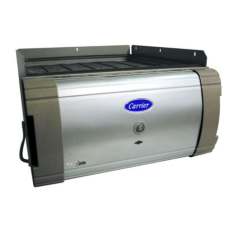
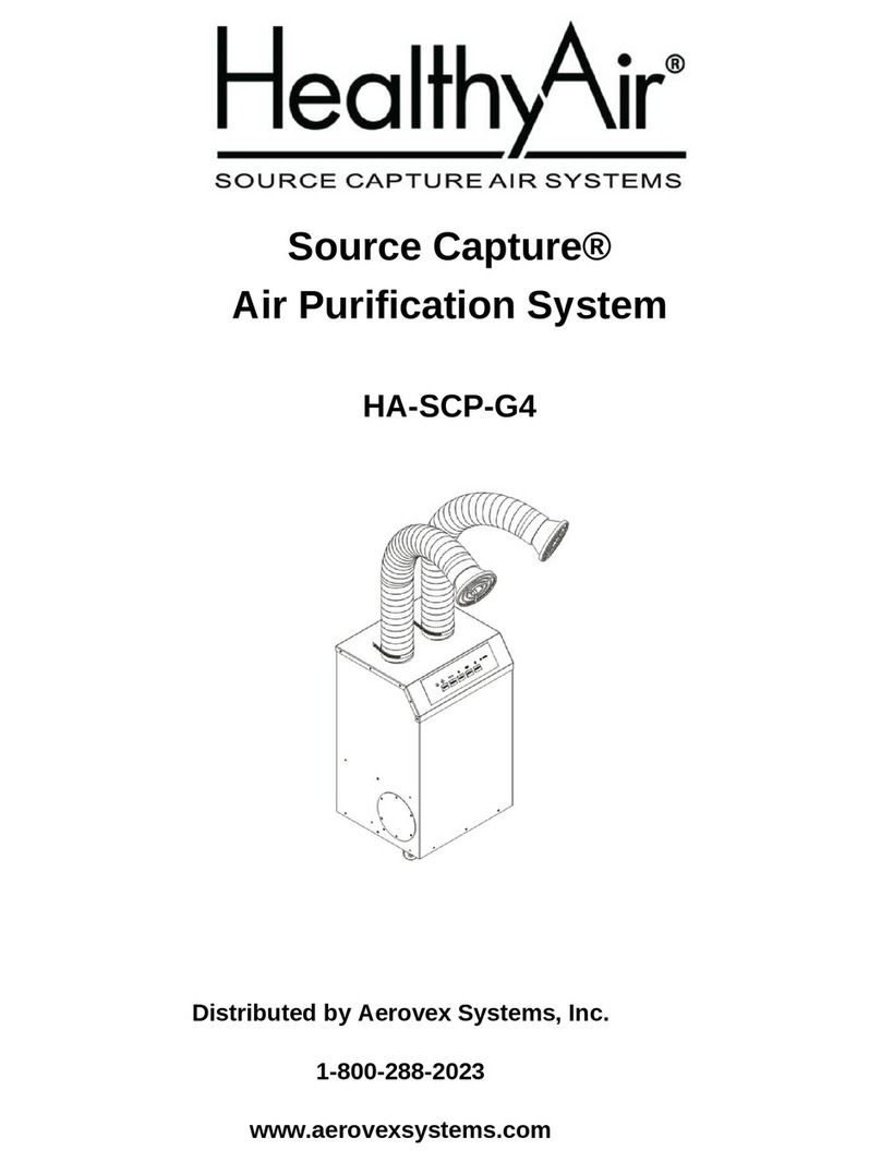
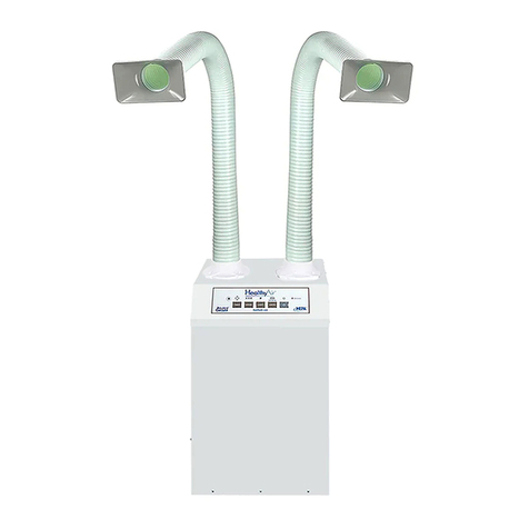
HealthyAir HA-CMSC-G3-W User manual

Ceiling Mount Source Capture®
Air Purification System
HA-CMSC-G3-W
Owner’s Manual
Table of Contents
HealthyAir® Series 1219 Filters
1
Important Safety Instructions
2
Technical Specifications
3
Packaging Reference
4-5
Component Reference
6
Installation Instructions for HA-CMSC-G2-3-WS/WD-R & -OV
7-14, 24-29
Installation Instructions for HA-CMSC-G2-4-W-R & -OV
15-23, 24-29
Electrical Wiring Instructions
30
Electrical Wiring Schematic
31
Operation Guidelines
32-33
Filter Replacement
34-38
Maintenance
39
Basic Service and Troubleshooting
40-44
1-Yeart Limited Warranty
45
Product Registration Form
46
Healthy Air Inc.
800-259-2535
www.HealthyAir.com

1
HealthyAir®HA-CMSC-G2-R & HA-CMSC-G2-OV
Ceiling Mount Source Capture®
Air Purification Systems
with
HealthyAir®Series 1219-CM Filters
HA-PF-1219 HA-EH-1219 HA-CC-1219
at
www.HealthyAir.com

2
WARNING
Cut power to the unit before servicing or replacing filters. Failure to
do so could result in serious personal injury and death.
I. Important Safety Instructions
Read the Owner's Manual and Important Safety Instructions carefully. Failure to
follow these instructions could cause a malfunction of the filter or unsatisfactory
performance. Follow a regular service and maintenance schedule for efficient
operation.
To reduce the risk of electric shock, fires, and/or injury:
•Do not use the air purifier in wet or damp locations
•Do not use outdoors
•Do not use at ambient temperature of above 95°F/35°C
•Do not use fabrics or other material to cover the inlet and outlet of the unit
•Do not allow children to operate or play with the unit
For safety reasons and to prevent electric shock, cut power to the unit under the
following conditions:
•When not in use for a long period of time
•When cleaning, servicing the machine or during replacement of filters
•When moving the air purifier
To prevent electric shock, do not dismantle, repair or modify this product.
Maintenance and cleaning instructions should be followed exactly as directed in
this manual. In case of malfunction, please contact an authorized distributor or
Healthy Air Inc. for service instructions.
To reduce the risk of electric shock, the unit has grounding type wiring that has a
third (grounding) wire. The unit must be hard wired, and all wiring must comply
with applicable electrical codes and ordinances. Do not alter the wiring.
3
II. Technical Specifications
Model Numbers
HA-CMSC-G3-3-W
HA-CMSC-G3-4-W
Rated Voltage
120V/60HZ
Power Consumption
200W
Unit Weight
65 lbs. (29 kg) Recirculating Vent
75 lbs. (34 kg) Outside Vent
Base Dimensions
24x24x15.4 in. (600×600×392 mm)
Air Flow Rate
550 cfm (930 m3/h)
Noise Level
56 dB

4
III. Packaging Reference
The HealthyAir®Ceiling Mount Source Capture®Air Purification System, model
HA-CMSC-G3-3-WS/WD, is packaged in two (2) boxes as follows:
Note, in cases when multiple units are ordered, or customized orders are placed,
the secondary items may be packed in additional boxes.
Box 1:
•(1) Air Purification Unit w/ (3) Series 1219-CM Filters, (4) Eye
Bolts,
(1) Remote Control, (1) Manual
Box 2:
•(1/2) Inlet Tube, (1/2) Flex Hose, (1/2) Hood, (1/2) Hose Clamp,
(1/2) Grillew/ LED Bulb & Wiring (Optional), (2) Outlet Vent
Cover Plates (Optional)

5
III. Packaging Reference
The HealthyAir®Ceiling Mount Source Capture®Air Purification System, model
HA-CMSC-G3-4-W, is packaged in three (3) boxes as follows:
Box 1:
•(1) Air Purification Unit w/ (3) Series 1219-CM Filters, (4) Eye
Bolts, (1) Remote Control, (1) Manual
Box 2:
•(1) Inlet Tube, (1) Gooseneck w/ (1) Centering Piece, (1) Flex
Hose w/ (1) Hose Clamp, (2) Outlet Vent Cover Plates (Optional)
Box 3:
•(1) Hood, (1) LED Bulb, (1) Handle

6
IV. Component Reference
12. Eye Bolt
13. Capacitor
14. HV PCB
15. PCB Board
16. Wiring Box
17. Safety Switch
18. Fuse
19. Control Panel
20. Control Panel Display
21. Remote Control
1. Thumb Screw
2. Face Plate
3. Pre-Filter
4. eGrid®
5. eHEPA®Filter
6. Activated Carbon Filter
7. Fan Coil
8. Blower/Motor
9. HV Contact Spring
10. Outside Vent Outlet Port
11. Main Box

7
V. Installation Instructions
HA-CMSC-G3-3-WS/WD
5.1 Install Eye Bolts
5.1.1 Carefully place the unit face down, as shown in Fig. 1.
5.1.2 Screw the four (4) Eye Bolts into the respective rivet nuts, located at the
four corners of the Bottom Plate.
5.1.3 Ensure that each Eye Bolt is fully and securely installed.
Fig. (1) –Installing Eye Bolts
Eye Bolt
Face Plate
Bottom Plate

8
V. Installation Instructions
HA-CMSC-G3-3-WS/WD
5.2 Optimal Unit Location
For optimal performance, the HealthyAir®Ceiling Mount Source Capture®Air
Purification System should be located such that the Hood can be strategically
positioned about 6” from the source of contaminants.
The unit should also be installed where it can be easily accessed and opened
for periodic filter replacement. Refer to Section 9.2 for filter replacement
details.
5.2.1 The unit is designed to be installed in place of a standard 2'x2’ ceiling tile,
and it must be securely attached to the building structure for adequate
support.
5.2.2 Depending on the type of building structure, and whether the ceiling has
I-Beam or concrete construction, follow the appropriate protocol for
proper installation and support of the unit.
5.3 Mount to I-Beam Ceiling Structure
Using Fig. 2 as a guide, install the HealthyAir®Ceiling Mount Source Capture®
Air Purification System in accordance with all applicable building and
mechanical codes.
Fig. (2) –Mounting Unit to I-Beam Ceiling
I-Beam
12 Gauge
Wire Rope
M6 Nut
Suspended Ceiling
Eye Bolt

9
V. Installation Instructions
HA-CMSC-G3-3-WS/WD
5.4 Mount to Concrete Ceiling Structure
Using Fig. 3 as a guide, install the HealthyAir®Ceiling Mount Source Capture®
Air Purification System in accordance with all applicable building and
mechanical codes.
Fig. (3) –Mounting Unit to Concrete Ceiling
Concrete Ceiling
Expansion Tube
Suspended Ceiling
M6 Nut
M6 Expansion Screw
& M6 Screw

10
V. Installation Instructions
HA-CMSC-G3-3-WS/WD
5.5 Install Inlet Tube
The Face Plate of the unit has two (2) 4” Ø Inlet Ports. One of the Inlets
Ports may be sealed with an Inlet Port Cover Plate, while the other is
uncovered.
Note that, for Single Inlet operation, either Inlet Port can be used depending
on the preferred arrangement. For Dual Inlet operation, remove the Inlet
Port Cover Plate to use both Inlet Ports.
5.5.1 Unscrew and remove the three (3) Thumb Screws that are
pre-mounted around the uncovered 4” Ø Inlet Port on the Face
Plate, as shown in Fig. 4.
Fig. (4) –Face Plate with Inlet Port
5.5.2 To wire the optional LED Lighting, reach into the Inlet Port and
carefully pull the LED Cable Socket out from within the unit. Note
that, the Face Plate may need to be opened to access the LED
Cable Socket if it cannot be easily reached.
Thumb
Screw
Inlet Port
Screw &
Washer

11
V. Installation Instructions
HA-CMSC-G3-3-WS/WD
5.5 Install Inlet Tube
5.5.3 With the Inlet Tube positioned near, and aligned with, the Inlet Port,
pass the LED Cable Socket though the Inlet Tube.
5.5.4 The flange of the Inlet Tube has a three-hole cutout pattern, as shown in
Fig. 5. Align the cutouts on the flange with the three (3) Screw and
Washers that are pre-installed around the Inlet Port. Then press the
Inlet Tube flush against the Face Plate and rotate the Inlet Tube
counterclockwise to lock it in place.
5.5.5 Secure the Inlet Tube to the Face Plate by reinstalling and screwing in
the (3) Thumb Screws.
Fig. (5) –Installing Inlet Tube on Face Plate
Inlet Tube
Cut-out on
Inlet Tube
Flange
Thumb
Screw

12
V. Installation Instructions
HA-CMSC-G3-3-WS/WD
5.6 Install Flex Hose
The Flex Hose is constructed of interlocking bands that enable its length and
shape to be adjusted. Note that, the Flex Hose will unravel if it is lengthened or
bent past its tolerance point. The diameter of the Flex Hose can be also
adjusted by rotating sections of the hose counterclockwise.
Note, if the LED Lighting option was selected, proceed to complete the
instructions in Section 5.7 prior to doing the following.
5.6.1 Remove the two (2) Thumb Screws that are installed on the Inlet Tube,
as shown in Fig. 6.
Fig. (6) –Inlet Tube with Thumb Screws
5.6.2 Note that, there are two (2) Screw Holes at the base of the Flex Hose
that match the two (2) Screw Holes in the Inlet Tube.
5.6.3 Slide the end of the Flex Hose over the Inlet Tube and align the two (2)
Screw Holes in the Flex hose with the two (2) Screw Holes in the Inlet
Tube, as shown in Fig. 7.
5.6.4 Reinstall the two (2) Thumb Screws, such that they pass through the
Screw Holes, to secure the Flex Hose to the Inlet Tube.
5.6.5 Position the Hose Clamp directly beneath the Thumb Screws on the
Flex Hose and screw the hex nut to tighten the Hose Clamp.
Thumb
Screw
Thumb
Screw

13
V. Installation Instructions
HA-CMSC-G3-3-WS/WD
5.6 Install Flex Hose
Fig. (7) –Installing Flex Hose on Inlet Tube
Flex Hose
Thumb Screw
LED Cable
(Option)
Screw Hole
Screw Hole

14
V. Installation Instructions
HA-CMSC-G3-3-WS/WD
5.7 Install LED Lighting (Optional Feature)
Note that, the LED Lighting system is an optional feature. To add this feature
visit www.HealthyAir.com and contact Healthy Air Inc.
5.7.1 Mount the LED Light Bulb on the Grill, by inserting the lip of the bulb
into the 4-piece cylinder located in the center of the Grill.
5.7.2 Connect the LED Cable to the LED Light Bulb, by sliding the two (2)
prongs of the bulb into the G4 Bulb Mount.
5.7.3 Pass the LED Cable through the Hood and entire length of the Flex
Hose, such that the LED Cable Plug passes through the bottom of the
Flex Hose.
5.7.4 Connect the Grill to the Hood by snapping the Grill onto the rim of the
Hood, as shown in Fig. 8.
5.7.5 Connect the LED Cable Plug to the LED Cable Socket, of the LED
Cable that is preinstalled in the unit, and Inlet Port.
Fig. (8) –Installing LED
Grill
LED Bulb
LED Cable w/
Bulb Mount

15
V. Installation Instructions
HA-CMSC-G3-4-W
5.8 Install Eye Bolts
5.8.1 Carefully place the unit face down, as shown in Fig. 9.
5.8.2 Screw the four (4) Eye Bolts into the respective rivet nuts, located at the
four corners of the Bottom Plate.
5.8.3 Ensure that each Eye Bolt is fully and securely installed.
Fig. (9) –Installation of Eye Bolts
Eye Bolt
Face Plate
Bottom Plate

16
V. Installation Instructions
HA-CMSC-G3-4-W
5.9 Optimal Unit Location
For optimal performance, the HealthyAir®Ceiling Mount Source Capture®Air
Purification System should be located such that the Hood can be strategically
positioned 6-12” from the source of contaminants.
The unit should also be installed where it can be easily accessed and opened
for periodic filter replacement. Refer to Section 9.2 for details.
5.9.1 The unit is designed to be installed in place of a standard 2'x2’ ceiling tile,
and it must be securely attached to the building structure for adequate
support.
5.9.2 Depending on the type of building structure, whether the ceiling has an
I-Beam or concrete construction, follow the appropriate protocol for
proper installation and support of the unit.
5.10 Mount Unit to I-Beam Ceiling Structure
Using Fig. 10 as a guide, install the HealthyAir®Ceiling Mount Source Capture®
Air Purification System in accordance with all applicable building and
mechanical codes.
Fig. (10) –Mounting Unit to I-Beam Ceiling
I-Beam
12 Gauge
Wire Rope
M6 Nut
Suspended Ceiling
Eye Bolt

17
V. Installation Instructions
HA-CMSC-G3-4-WS
5.11 Mount Unit to Concrete Ceiling Structure
Using Fig. 11 as a guide, install the HealthyAir®Ceiling Mount Source Capture®
Air Purification System in accordance with all applicable building and
mechanical codes.
Fig. (11) –Mounting Unit to Concrete Ceiling
Concrete Ceiling
Expansion Tube
Suspended Ceiling
M6 Nut
M6 Expansion Screw
& M6 Screw

18
V. Installation Instructions
HA-CMSC-G3-4-W
5.12 Assemble Inlet Tube and Gooseneck
Note that, the Inlet Tube and Gooseneck are typically shipped preassembled. If
that is the case, the following two sections may be bypassed, and the
installation process will continue at Section 5.14. However, if these items need
to be assembled, or reassembled at any point, then proceed as follows:
5.12.1 Install the 3.5” Ø Centering Piece on the threaded end of the Gooseneck
and secure it in place by screwing on the M16 Hex Nut, as shown in Fig.
12.
5.12.2 Remove the Thumb Screw that is preinstalled within the base of the Inlet
Tube.
5.12.3 Slide the split end of the Gooseneck into the square channel located in
the center of the Inlet Tube. Ensuring that the Gooseneck is inserted all
the way, such that the screw hole in the Gooseneck aligns with the
screw hole in the Inlet Tube.
5.12.4 Reinstall and screw in the Thumb Screw, to secure the Gooseneck to
the Inlet Tube, as shown in Fig. 12.
Fig. (12) –Assembling Inlet Tube and Gooseneck
Centering
Piece
Gooseneck
M16 Hex Nut
Inlet Tube
Thumb
Screw

19
V. Installation Instructions
HA-CMSC-G3-4-W
5.13 Assemble Inlet Tube and Flex Hose
The Flex Hose is constructed of interlocking bands that enable its length and
shape to be adjusted. Note that, the Flex Hose will unravel if it is lengthened or
bent past its tolerance point. The diameter of the Flex Hose can be also
adjusted by rotating sections of the hose counterclockwise.
5.13.1 Install the Flex Hose on the Inlet Tube by sliding the end of the Flex
Hose over the Inlet Tube, as shown in Fig. 13. Note that, if the
diameter of the Flex Hose needs to be increased to fit over the Inlet
Tube, rotate the end of the Flex Hose counterclockwise.
5.13.2 Hold the end of the Flex Hose over the Inlet Tube and rotate it
clockwise, to reduce its diameter and tightly fit it to the diameter of the
Inlet Tube.
5.13.3 Position the Hose Clamp at the base of the Flex Hose and screw the
hex nut to tighten the Hose Clamp and secure the Flex Hose on the
Inlet Tube.
Fig. (13) –Assembling Inlet Tube and Flex Hose
Inlet Tube
Flex Hose
Hose Clamp
Holes for Hood
Installation
Table of contents
Other HealthyAir Air Cleaner manuals

HealthyAir
HealthyAir Source Capture HA-SSC-G4-AE User manual

HealthyAir
HealthyAir HA-PAP-G3 User manual

HealthyAir
HealthyAir Source Capture HA-SCP-G4-W User manual

HealthyAir
HealthyAir HA-SCP-G5-AE User manual

HealthyAir
HealthyAir Source Capture HA-SCE-G2 User manual

HealthyAir
HealthyAir HA-CMSC-G2-R User manual

HealthyAir
HealthyAir HA-CMP-G2-R User manual

HealthyAir
HealthyAir HA-SSC-G5 User manual

HealthyAir
HealthyAir HA-PAP-G2 User manual

HealthyAir
HealthyAir Source Capture HA-SCP-G4-WS-R User manual