HEIDENHAIN ND 231 User manual

HEIDENHAIN
REF
2
1SET
in.
=
<>
789
456
123
0.–
CL
MOD
HEIDENHAIN
•Clear entry
• Reset to zero (P80!)
• CL plus MOD:
parameter list
• CL plus 2-digit num-
ber: select parameter
• Clear parameter entry
and show parameter
number
Status display •Algebraic
sign
• Decrease
parameter
value
Actual value and input display
(7-segment LED,
9 decades and sign)
•Select datum
• Page backward in
parameter list
•Confirm entry value
• Set display to value from
P79 (P80!)
Numeric keypad
•Decimal point
• Increase pa-
rameter value
•Output measured value over data
interface (P86!)
• Go to parameter list after switch-on
• Page forward in parameter list
ND 231
Working with the measured
value display unit
Indicator Meaning
REF If decimal points are blinking:
Display is waiting for the reference mark to be crossed over.
If decimal points are not blinking:
Reference marks crossed over – datum points are now stored in
nonvolatile memory.
Blinking: Waiting for operator to press ENT or CL.
in. Position values displayed in inches.
1 / 2 Datum point 1 / Datum point 2 currently active.
SET Blinking: Waiting for operator to confirm entry values.
< / = / > Sorting mode: Measured value less than lower limit / within
tolerances / greater than upper limit.

The ND 231 measured value display unit is designed for use with two HEIDENHAIN
linear or rotary encoders with sinusoidal output signals.
Each encoder has one reference mark or several reference marks, which may also be
distance-coded
. When a reference mark is crossed over, it generates a signal identify-
ing that position as a reference point. After switch-on, crossing over the reference
marks of both encoders restores the relationship between display values and axis
slide positions last established by datum setting.
With distance-coded reference marks, a maximum traverse of only 20 mm after
switch-on suffices to re-establish the datum.
Switch-On
If you do not wish reference mark evaluation, press CL instead of ENT.
Datum Setting
The datum setting procedure assigns a specific axis position to the associated display
value. The datum point refers to one of the two encoders or the sum or difference
value (see "Selecting the display").
You can set two separate datum points.
Cross over the reference marks in both axes.
Move both axes until the display becomes active and no
decimal points blink.
The display unit is now ready for operation.
5 , 6 9 7
Ent...CL
0 ➤1Turn on the power (switch located on rear panel).
•Display shows
•REF blinks
Select datum point 1 or 2.
Enter a numerical value, such as 40.
You can switch from one datum to the other at any time.
Use datum 2 when you want to display incremental dimensions.
4 0
Confirm your entry.
Switch on reference mark evaluation.
•The display shows the value last assigned to the
reference mark position.
•REF glows
•Decimal points blink

Selecting the Display
You select the display for the ND 231 with
•switching inputs (see D-sub connection EXT) or
•operating parameter P06 (see list of operating parameters).
If you select the display over the switching inputs, operating parameter P06 has no
effect on the display.
If none of the inputs is active for selection of the display (pins 6 to 9) or if more than
one of these inputs is active, operating parameter P06 selects the display:
•Position of encoder X1: P06 =
•Position of encoder X2: P06 =
•Sum display: P06 =
•Difference display: P06 =
Sorting and Tolerance Check Mode
In this mode the display value is compared with an upper and lower limit value.
Status indicators and the switching outputs on the D-sub connection EXT indicate
whether the display value is less than the lower limit, greater than the upper limit, or
between the two limit values.
Indicator Meaning
=Measured value is between the limit values
<Measured value is less than the lower limit value
>Measured value is greater than the upper limit value
Operating parameters for the sorting mode:
•P17: Sorting on/off
•P18, P19: Limit values

1GND
2
3
4
5
6
20
7
TXD
RXD
RTS
CTS
DSR
GNDSIGNAL
DTR
CHASSIS 1 GND
2
3
4
5
6
20
7
TXD
RXD
RTS
CTS
DSR
GNDSIGNAL
DTR
CHASSIS
ND
11GND
2
3
4
5
6
20
7
TXD
RXD
RTS
CTS
DSR
GND
SIGNAL
DTR
CHASSIS
2
3
4
5
6
20
7
ND
GND
TXD
RXD
RTS
CTS
DSR
GND
SIGNAL
DTR
CHASSIS
Data Output
There are three ways to output data:
➤Press the MOD key. This only works when operating parameter P86 is set to
(see operating parameter list)
➤Input the command STX (Ctrl B) over the RXD input
➤Input a latch command over the D-sub connection EXT.
A connecting cable (for example to a PC) is available from HEIDENHAIN
(Id.-Nr. 274 545 ..). Cables up to 20 m (66 ft) are permitted.
Operating parameters for data output: P50, P51
Wiring and pin layout
Connecting cable is either fully wired (left) or only partially wired (right).
CHASSIS GND: Chassis Ground TXD: Transmitted Data RXD: Received Data
RTS: Request To Send CTS: Clear To Send DSR: Data Set Ready
SIGNAL GND: Signal Ground DTR: Data Terminal Ready
Signals Signal levels “active” Signal levels “not active”
TXD, RXD –3 V to –15 V +3 V to +15 V
RTS, CTS, DSR, DTR +3 V to +15 V –3 V to –15 V
Data transfer format and control characters
Format ASCII code
Data word 1 start bit, 7 data bits, parity bit (even parity), 2 stop bits
Control characters Call measured value: STX (CTRL B), interrupt DC3 (CTRL S),
resume DC1 (CTRL Q)
Enquire error message: ENQ (CTRL E)
Sequence •Sign •Numerical value with decimal point •Blank space
•Unit (blank space = mm, " = inches, ? = error)
•Sorting result (<, >, =; ? if P18 > P19) or
blank space
•Axis designation (1=X1, 2=X2, A=X1+X2, S=X1–X2)
•Carriage return •Line feed
Storage and transfer times
The duration of data transfer depends on the selected baud rate and the number of
additional line feeds.
Latch signal STX(CTRL B) EXT (pulse) EXT (contact) PRINT
Storage time ≤1 ms ≤1 µs ≤5 ms ≤331) ms
Data transfer after ≤341) ms ≤331) ms ≤381) ms ≤662) ms
1) These times will increase by 15 ms per compensated axis if linear compensation is active, and by another 28 ms if the
comma position, counting mode and subdivision are different.
2) This time will increase by 30 ms per compensated axis if linear compensation is active, and by another 56 ms if the comma
position, counting mode and subdivision are different.

OutputsInputs
Danger to internal components!
Voltage sources from external circuitry must conform to the recommendations
in EN 50 178 for low-voltage electrical separation. Connect inductive loads only
with a quenching diode parallel to the inductance.
Use only shielded cable!
Connect the shield to the connector housing.
BUCE
E
C
Pin 1.10 0 V
+ UB≤32 V
I ≤100 mA
D-sub connection EXT
Pin Function Pin Function
15 Meas. value ≥trigger limit A1 (P62) 1 0 V
16 Meas. value ≥trigger limit A2 (P63) 10 0 V
17 Meas. value < lower sorting limit (P18) 5 Do not assign
18 Meas. value > upper sorting limit (P19) 12 Do not assign
19 Error (see “Error Messages”) 13 Do not assign
14 Display value is zero 11 Vacant
2 Reset display to zero 20 Vacant
3 Set display to value in P79 21 Vacant
4 Ignore reference mark signals (encoder X1)
24 Ignore reference mark signals (encoder X2)
6 Display position of encoder X1
7 Display position of encoder X2
8 Display sum X1 + X2
9 Display difference X1 –X2
22 Pulse: Output the measured value
23 Contact: Output the measured value
25 Switch off or activate REF mode:
(current REF condition is changed)
Signal levels Low High
Inputs –0.5 V ≤U ≤0.9 V I ≤6 mA 3.9 V ≤U ≤15 V
Outputs U ≤0.4 V I ≤100 mA U ≤32 V I ≤10 µA
Description of input and output signals
Input signals •Internal 1 kΩ pull-up resistor
•Triggering by make contact against 0 V or
Low level over TTL logic device
•Delay for zero reset/preset: td≤2 ms
•Min. pulse duration for all signals: tmin ≥331) ms
Output signalsOutput signals
Output signals •Open collector outputs,
active Low
•Signal output delay:
td≤29 ms1)
•Duration of zero cross-
over signal, trigger out-
puts A1,A2: t0≥180 ms
1) The indicated times will increase
•by 15 ms per compensated axis if linear compensation is active
•by 20 ms if comma position, counting mode and subdivision different
•during external zero reset, preset, latching or data output.

Display Freeze by Measured Value Output Signal
The effect of the signal for measured value output on the display is defined in user
parameter P23.
➤Concurrent display: No display freeze. The unit shows the current measured
value ( ).
➤Frozen display: The display is frozen and is updated with each signal for
measured value output ( ).
➤Frozen/concurrent display: The display freezes only as long as the signal is
present ( ).
Error Messages
To clear error message
When you have removed the cause of the error,
➤press
Message Cause and effect
Last measured value not yet latched1)
External device not ready for data transfer1)
( only appears once)
Data interface:
Parity error or wrong transfer format1)
Incorrect input value
Overflow caused by external preset
Overflow, trigger limit 1
Overflow, trigger limit 2
Overflow, lower sorting limit
Overflow, upper sorting limit
Sum or difference cannot be displayed
Signal from encoder input X1 or X2 too small1)
(encoder may be contaminated)
Input frequency for too high for input X1 or X21)
(can occur when the traverse speed is too high)
Internal counter overflow1)
Error while crossing over reference marks1)
To clear the error message: Switch off the display unit.
Should any of these error codes recur, contact your HEIDENHAIN
service agency.
Offset compensation values for encoder signals have been
erased: contact your HEIDENHAIN service agency.
Erase the operating parameters.
If all decimal points light up, the measured value is too large or too small.
In this case, set a new datum or retract.
If all sorting indicators light up, the upper sorting limit is less than the lower
sorting limit.
1) These errors are significant for a connected device.
The error signal (pin 19) at the D-sub connection EXT is active.

Operating Parameters
The parameters are divided into “user parameters“and “protected operating
parameters," which can only be accessed by entering a code number.
User parameters
User parameters are operating parameters that you can change without entering the
code number: They are designated P00 to P30, P50, P51, P79, P86
Calling user parameters
To call user parameters immediately after switch-on:
➤➤
➤➤
➤Press the MOD key as long as is visible in the display.
To call user parameters during operation:
➤➤
➤➤
➤Press and hold the CL key, then press MOD.
To go directly to a specific user parameter:
➤➤
➤➤
➤Press and hold the CL key, then press the first digit of the parameter number.
➤➤
➤➤
➤Release both keys and press the second digit.
Protected operating parameters
Before you can change protected operating parameters you must enter the code
number 95 148 through : They remain accessible until you switch off
the position display.
To page through the parameter list
➤➤
➤➤
➤Forward paging: Press the MOD key.
➤➤
➤➤
➤Backward paging: Press the 1 / 2 key.
By paging on, you automatically enter any change you've made in a parameter.
To change operating parameters
➤➤
➤➤
➤Increase the parameter value with the decimal point key, or
➤➤
➤➤
➤Decrease the parameter value with the minus key, or
➤➤
➤➤
➤Enter the numerical value for the operating parameter, e.g. for P41 ( SET blinks).
To correct your entries and show the parameter designation
➤➤
➤➤
➤Press the CL key.
To exit the operating parameters
➤➤
➤➤
➤Press ENT. All changes made become effective.
Operating Parameter List
Parameter Meaning Function / Effect Setting
To change a protected operating parameter, enter
code number 95 148.
Unit of measure Display in millimeters
Display in inches
Select display Display for encoder at X1
mode Display for encoder at X2
Sum display X1 + X2
Difference display X1 –X2
Sorting mode Sorting on
Classification
Sorting off
Lower sorting limit (ensure that P18 < P19)
Upper sorting limit (ensure that P19 > P18)

❋
❋
❋
❋
❋
❋
❋
❋
Parameter Meaning Function / Effect Setting
Display freeze Concurrent display, no freeze
Display
with measured Frozen display / update with signal
value output Frozen/concurrent display
CountingCounting
CountingCounting
Counting Normal
(Positive)
Direction
direction Inverse
(Negative)
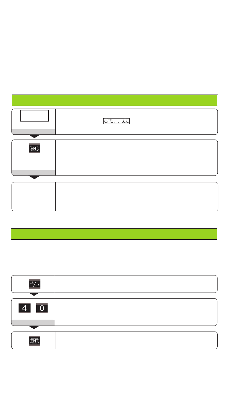
Subdivision of encoder signals 400, 320, 256, 200, 160, 128, 100,
Subdivision
80, 50, 40, 20, 10, 8, 5, 4, 2, 1, 0.8, 0.5, 0.4, 0.2, 0.1
Counting 0-1-2-3-4-5-6-7-8-9-0
mode 0-2-4-6-8-0
0-5-0
Places after decimal 2 / 3 / 4 / 5 / 6 (up to 8 with inch display)
Decimal point
Linear error compensation1)
Compensation
–99 999,9 < P41 < + 99 999,9 [µm/m]
Reference One reference mark
marks Distance-coded with 500 •SP
(SP = signal period)
Distance-coded with 1000 •SP
(e.g. for LS 303 C / LS 603 C)
Distance-coded with 2000 •SP
Distance-coded with 5000 •SP
Reference mark Evaluation
evaluation No evaluation
Encoder No monitoring
(Alarm Off)
Encoder
monitoring Contamination
Frequency
Contamination and frequency
Baud rate
110, 150, 300, 600, 1200, 2400, 4800, 9600
Additional line feeds
(Linefeed)
0 to 99
Trigger limit 1 Enter numerical value
Trigger limit 2 Enter numerical value
Value for Enter numerical value for datum setting over
Preset
datum switching input or with ENT key
Reset/Preset No zero reset/preset with CL/ENT
Zero reset with CL (
Set Zero
),
no preset with ENT
Zero reset with CL and
preset with ENT to value in P79
Behavior after message displayed
Message
switch-on message not displayed
External REF REF over D-sub connection EXT
No REF over EXT connection
PRINT via MOD PRINT inhibited
Mode
key PRINT not inhibited
❋: Enter parameter separately for each encoder
1) Example entry value for P41 Displayed length: Ld= 620.000 mm; Actual length (determined e.g. with a
comparator system VM 101 from HEIDENHAIN): La= 619.876 mm; Length difference: ∆L = La– Ld= –124 µm
Compensation factor: k = ∆L / Ld= –124 µm / 0.62 m = –200 [µm/m]

Parameter Settings for HEIDENHAIN Linear Encoders
Example: Set parameters for any encoder
Linear encoder with signal period s = 10 µm
Desired display step a = 0.000 1 mm
Subdivision P32 = 0.001 • s / a ==
==
= 100
Counting mode
P33 = 1 (display counts 1, 2, 3 ...)
Decimal places of a: P38 = 4
Display step
(unit: P01) The following settings
apply for mm:
Model
Signal
period [µm]
Reference
mar s
P 43
mm inches Subdi-
vision
P32
Count.
mode
P33
Decimal
places
P38
CT
MT xx01 one single
none -
0,0005
0,0002
0,0001
0,00005
0,00002
0,00001
0,000005
0,000002
4
10
20
40
5
2
1
5
4
4
4
5
Recommen e only for LIP 401
LIP 401
2
one single
0,00002
0,00001
0,000005
0,000001
0,0000005
0,0000002
100
200
400
2
1
5
5
5
6
one singleLF 103
LF 401
LIF 101
LIP 501
ist.c. 5000
0,001
0,0005
0,0002
0,0001
0,00005
0,00005
0,00002
0,00001
0,000005
0,000002
4
8
20
40
80
1
5
2
1
5
3
4
4
4
5
Recommen e only for LIP 101
LIP 101
4
one single
0,00002
0,00001 0,000001
0,0000005 200
400 2
15
5
MT xx 10 one single 0,0005
0,0002
0,0001
0,00002
0,00001
0,000005
20
50
100
5
2
1
4
4
4
one singleLS 303
LS 603 20
ist.c. 1000
0,01
0,005 0,0005
0,0002 2
41
52
3
one singleLS 106
LS 406
LS 706 ist.c. 1000
ST 1201
20
none -
0,001
0,0005 0,00005
0,00002 20
40 1
53
4
one single 0,005
0,002
0,001
0,0005
0,0002
0,0001
0,00005
0,00002
8
20
40
80
5
2
1
5
3
3
3
4
Recommen e only for LB 302
LB 302
LIDA 10x
40
ist.c. 2000
0,0002
0,0001
0,00001
0,000005
200
400
2
1
4
4
one singleLB 301 100
ist.c. 1000
0,005
0,002
0,001
0,0002
0,0001
0,00005
20
50
100
5
2
1
3
3
3
LIM 102 12800 one single 0,1
0,05
0,005
0,002
128
256
1
5
1
2

Temperature range Operation: 0°C to 45°C (32°F to 113°F)
Storage: –30°C to 70°C (–22°F to 158°F)
Rel. humidity Annual average: < 75 %; maximum: < 90 %
Weight 1.5 kg
Power Supply and Connection
Primary-clocked power supply.
Voltage range: 100 V to 240 V (–15 % to + 10 %) Frequency: 48 Hz to 62 Hz
Power consumption: typ. 8 W Line fuse: F 1 A (in unit)
Minimum cross-section of the power line: 0.75 mm2
Rear Panel
X31 (V.24/RS-232-C) X41 (EXT)
100 ... 240 V
50 ... 60 Hz X1 X2
D-sub connection
EXT
Ground terminal
Installation
You can mount the display unit to a flat surface with M4
bolts (see illustration at right).
The units can also be stacked. Adhesive inserts (included
in delivery) prevent them from sliding.
Ambient Conditions
172 ±0.2
6.77 ±.008"
140 ±0.2
5.51 ±.008"
Power switch
Inputs for HEIDENHAIN linear encoders with
sinusoidal output signals (7µApp to 16 µApp),
connecting cable max. 30 m (98.5 ft), input
frequency max. 100 kHz
Data interface
RS-232-C/V.24
Interfaces X1, X2, X31 and X41 comply with the recommendations in
EN 50 178 for separation from line power.
Danger of electrical shock!
Unplug the power cord before opening the housing.
Connect a protective ground. This connection must never be interrupted.
Danger to internal components!
Do not engage or disengage any connections while the unit is under power.
Use only original replacement fuses.
To increase the noise immunity, connect the ground terminal on the rear panel
to the central ground point of the machine. (Minimum cross-section: 6 mm2)
284 252-24 ·SW 246 182 01 ·1 ·3/2000 ·H ·Printed in Germany ·Subject to change without notice
DR. JOHANNES HEIDENHAIN GmbH
Dr.-Johannes-Heidenhain-Straße 5
D-83301Traunreut, Deutschland
(0
86
69) 31-0 .56 832
(0
86
69) 50
61
FAX
FAX
Service (0
86
69) 31-12
72
TNC-Service (0
86
69) 31-14
46
(0
86
69) 98
99
Tx
http://www.heidenhain.de
Table of contents
Other HEIDENHAIN Monitor manuals

HEIDENHAIN
HEIDENHAIN ND 281B User manual

HEIDENHAIN
HEIDENHAIN VRZ 650 Instruction sheet

HEIDENHAIN
HEIDENHAIN ND 730 User manual

HEIDENHAIN
HEIDENHAIN ND 261 User manual

HEIDENHAIN
HEIDENHAIN ND 780 User manual

HEIDENHAIN
HEIDENHAIN BC 110BF User manual

HEIDENHAIN
HEIDENHAIN ND 286 User manual

HEIDENHAIN
HEIDENHAIN ND 710 User manual

HEIDENHAIN
HEIDENHAIN ND 282B User manual

HEIDENHAIN
HEIDENHAIN BE 411F User manual