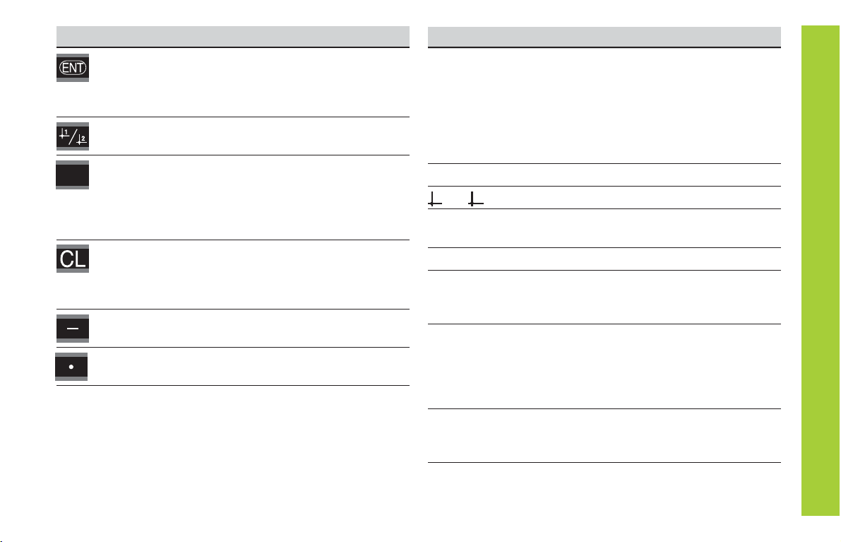
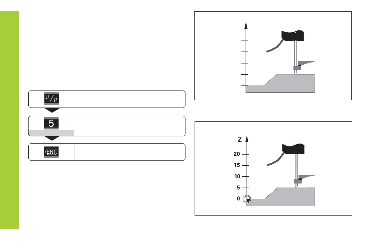
HEIDENHAIN ND 282B User manual

English (en)
4/2001
Measured Value
Displays
User’s Manual
ND 282
B

2
Numeric keypad
with decimal point
Status display with indicators
Display of actual value and input
(8 decades with algebraic sign)
HEIDENHAIN
789
456
123
0.CL
MOD
REF SET START PRINT inch
MIN ACTL MAX DIFF
=
<>
21

3
Key Function
• Set datum
• Transfer input value
• Set display to value from P79 (P80!)
• Leave parameter list
• Select datum
• Page backwards in parameter list
• Start series of measurements
• Switch display for measurement series
• Start measured value output “PRINT”
• Select parameter after switch-on
• Page forward in parameter list
• Delete entry
• Set display to zero (P80!)
• CL plus MOD: select parameter list
• CL plus number: select parameter
• Algebraic sign
• Reduce parameter value
• Decimal point
• Increase parameter value
MOD
Indicator Meaning
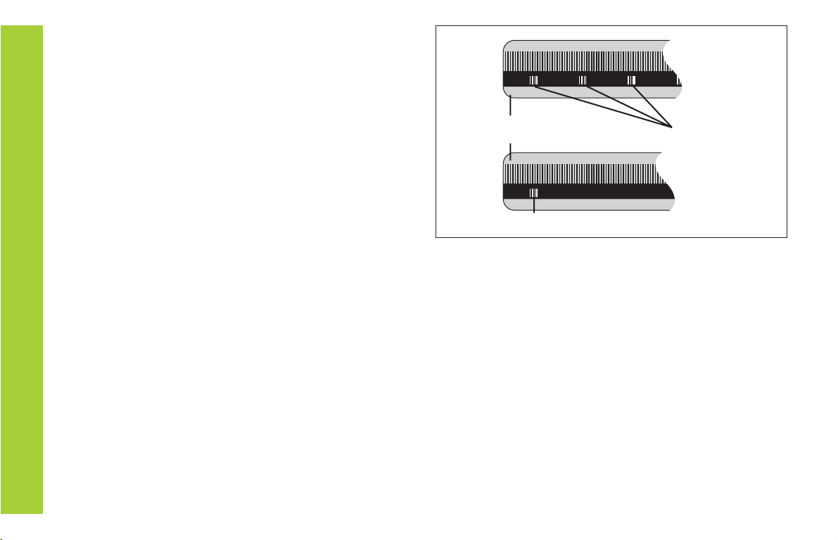
REF If the decimal points are also blinking:
Display is waiting for reference mark
traversing. If decimal points are not blinking:
Reference mark has been traversed—display
stores datum points in nonvolatile memory
Blinking: display is waiting for ENT or
CL to be depressed
inch Position values in inches
1 / 2 Selected datum point
PRINT Blinking: Display is waiting for ENT to
be pressed for data output
SET Blinking: Display is waiting for input values
< / = / > Sorting and tolerance checking:
measured value smaller than lower limit /
within the limits / greater than upper limit
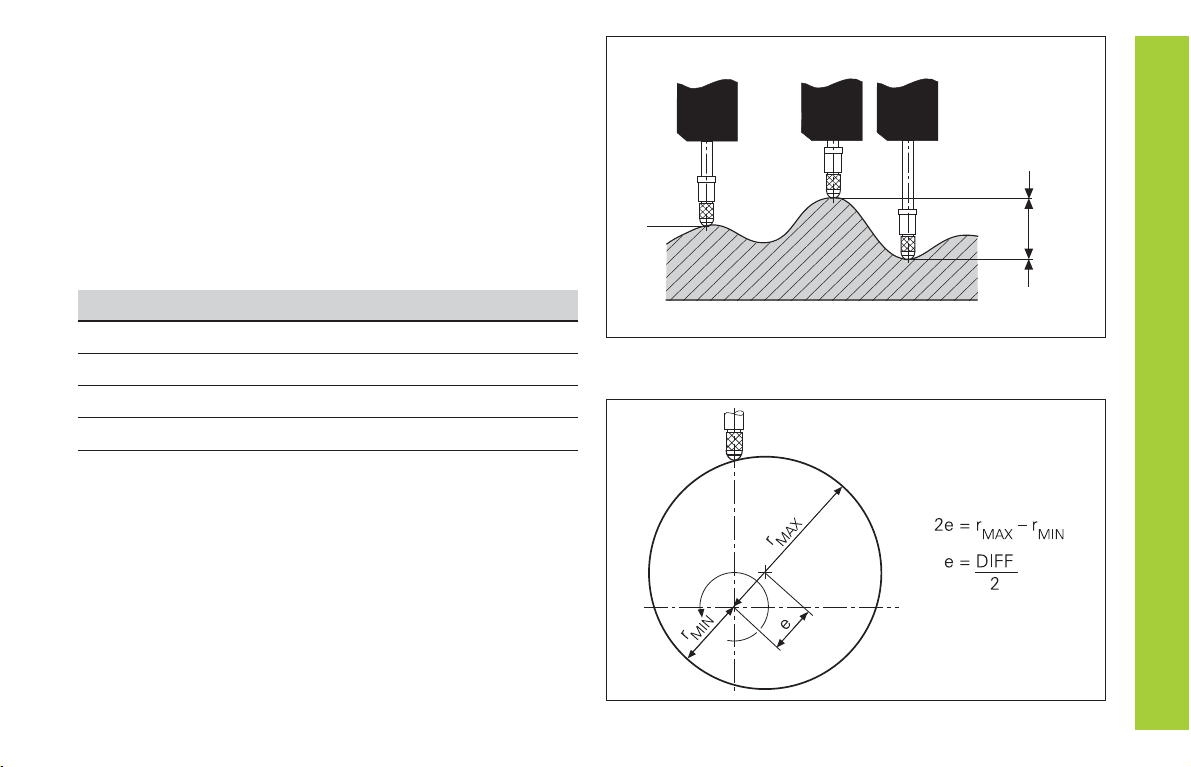
MIN
/
MAX / Series of measurements: Minimum /
maximum / greatest difference (MAX–MIN) /
current measured value
Blinking: Confirm selection or deselect
function
START Series of measurements is running
Blinking: Display is waiting for signal to
start series of measurements
DIFF / ACTL

4
Items supplied with ND 282 B
ND 282 B Measured value display unit,
benchtop model
Encoder input 11 µAPP Id. Nr. 344 998-xx
Power cord 3 m (9.9 ft)
User's Manual ND 282 B
Adhesive plug-in feet For stacking ND 282 B units
This manual is for the ND 282 B measured value
display with the following software number or higher:
354 394-01
The software number is indicated on a label on the
rear panel.
Items Supplied

5
Installation and Specifications
Rear Panel, Accessories 16
Mounting 17
Power Connection 18
Operating Parameters 19
List of Operating Parameters 21
Linear Encoders 24
BCD Interface (X33) 27
Switching Inputs and Outputs EXT (X41) 29
Distance-to-Go Mode 34
Displaying the Software Version 35
Locking the Keypad 36
Specifications 37
Dimensions 38
Contents
Contents
Working with the ND Display Units
Encoders and Reference Marks 6
Switch-On, Traversing the Reference Marks 7
Datum Setting 8
Finding Minimum and MaximumValues 9
Sorting and Tolerance Checking 12
MeasuredValue Output 13
Error Messages 15

6
Position Encoders and Reference Marks
The ND 282 B display unit is designed for use with photo-
electrical linear encoders with 11 µAPP sinusoidal signals:
primarily for HEIDENHAIN MT length gauges with 11 µAPP.
The MT length gauges have one reference mark. The scales
of other photoelectric linear encoders (see “Linear Encod-
ers”) can contain one reference mark or many
distance-
coded
reference marks.
If there is an interruption of power, the relationship between
the position of the length gauge and the displayed position
value is lost. The reference marks on the position encoders
and the REF reference mark evaluation feature enable the
display unit to quickly reestablish this relationship again
when the power is restored.
When a reference mark is crossed over, a signal is generated
which identifies that position as a reference point. At the
same time, the display unit restores the relationship be-
tween length gauge position and display values which you
last defined by setting the datum.
To restore the datum on scales with distance-coded refer-
ence marks, you only need to traverse a maximum of 20 mm
for linear encoders.
Position Encoders and Reference Marks
Scale in Distance-coded
linear encoder reference marks
Reference mark
Reference marks on linear encoders

7
Turn on the power.
(Switch located on rear panel.)
•ND 282 B appears for two seconds.
•ENT ... CL 1) appears.
• REF indicator is blinking.
• Data interface shows error 7.
ENT...CL
Switch-on the reference mark evaluation
function.
• The position value that was last
assigned to the reference mark
position is displayed.
• REF indicator lights up.
• Decimal point is blinking.
5 , 6 9 7
Switch-On, Traversing the Reference Marks REF Mode
Crossing over the reference marks automatically switches the
display to REF mode: The last assignment of display values to
length gauge positions is stored in nonvolatile memory.
1) Press the CL key if you choose not to traverse the reference
marks. Note that, in this case, the relationship between
length gauge position and display value will be lost if the
power is interrupted or if the unit is switched off.
Û
Cross over the reference mark.
Move the plunger until the display starts
counting and the decimal point stops blink-
ing. The display is now ready for operation.
0
ä
1
For automation purposes, crossing over the reference marks
and the display ENT ... CL can be disabled with parameter P82.
Switch-On, Traversing the Reference Marks

8
Datum Setting
The datum setting procedure assigns a display value to a
known position. With the ND 200 series, you can set two
separate datum points.
There are several ways to set the datum:
• Enter a numerical value, or
• Transfer a value from an operating parameter
(see P79, P80), or
• By external signal
Select datum 1 or 2.
After datum setting: Assignment of measured values to
positions
Without datum setting: unknown assignment of measured
values to positions
Z
?
?
?
?
?
Enter numerical value (here 5),
SET blinks.
5
You can switch between datums 1 and 2 as desired. Datum 2
can be used, for example, for working with incremental dimen-
sions.
When you switch back to datum 1, the display unit resumes
display of the actual position of the MT.
Datum Setting
Confirmthe entered numerical value.

9
Series of measurements: The MIN, MAX and DIFF values of an
uneven surface
Example: Measurement series for determining eccentricity
e
Finding Minimum and Maximum Values
DIFF
MAX
MIN
ACTL
Finding Minimum and Maximum Values from a
Series of Measurements
After a series of measurements has been started, the display
transfers the first measured value to the memory for minimum
and maximum values. Every 0.55 ms, the display compares the
current measured value with the memory contents: A new
value is stored if it is greater than the stored maximum value or
smaller than the stored minimum value. At the same time, the
display calculates and stores the difference DIFF between the
current MIN and MAX values.
Display Meaning
MIN Minimum value from the series of measurements
MAX Maximum value from the series of measurements
DIFF Difference MAX – MIN
ACTL Current measured value
Starting the measurement series and selecting the display
You can start the series of measurements either by pressing
MOD and selecting the desired display—as described on the
following pages—or by external signal over the switching
inputs at the D-sub connection EXT (see section on X41).
When a series of measurements is started, the internal MIN/
MAX/DIFF memory is reset.

10
Finding Minimum and Maximum Values
Starting a series of measurements
Select the display for a series of meas-
urements.
The selected indicator blinks (here, MAX).
Confirm selection.
Repeatedly
MOD
... until the START indicator blinks.
MOD
Repeatedly
Switching between MIN, MAX, DIFF and ACTL displays
It is not possible to switch between the displays as
described below if the switching input for external
control of the series of measurements (pin 6 on
D-sub connection EXT) is active.
As an alternative, you can select the display with operating
parameter P21 (see “Operating Parameters”).
Select the new display of a series of
measurements.
The selected indicator blinks (here, MIN).
Confirm the change.
Repeatedly
MOD
The display now shows the smallest value measured during the
current series of measurements.
Indicator preselection
Press MOD to start the series of measurements and select the
display with the indicators.
Operating parameter P86 allows you to define which indicator
is displayed first when MOD is pressed.
Start the series of measurements.
MAX
START
MIN

11
Select the indicator START.
The indicator START blinks.
Starting a new series of measurements
Repeatedly
MOD
Start a new series of measurements.
Ending a series of measurements
Select the active indicator (MIN, ACTL,
MAX, DIFF).
The indicator that lit up last blinks.
End the series of measurements.
Repeatedly
MOD
START
Finding Minimum and Maximum Values
Select the indicator START.
The START indicator blinks.
End the series of measurements.
Repeatedly
MOD
or
START

12
Sorting and Tolerance Checking
In the sorting and tolerance checking mode, the display unit
compares the displayed value with the programmed upper
and lower sorting limits. The sorting and tolerance checking
mode is enabled and disabled with operating parameter
P17.
Entering sorting limits
Sorting limits are entered in operating parameters P18 and
P19 (see “Operating Parameters”).
Sorting signals
The indicators and switching outputs at D-sub connection
EXT (see section on X41) sort the display value into one of
three classes.
Display Meaning
=Measured value is within sorting limits
<Measured value is smaller than lower sorting
limit
>Measured value is greater than upper sorting
limit
Operating parameters for sorting and tolerance
checking
P17 CLASS. Sorting ON/OFF
P18 L.CLASS. Lower sorting limit
P19 U.CLASS. Upper sorting limit
Example: Upper sorting limit = 26.02 mm
Lower sorting limit = 26.00 mm
Part 1
Part 2
Part 3
Sorting and Tolerance Checking
Reject
Accept
Rework

13
Measured Value Output
For technical information on the BCD data inter-
face (X33), information on the data format, etc.,
see the chapter “BCD Interface (X33).”
Measured values can be output over the BCD interface (X33).
There are several ways to start measured value output:
ä
Press MOD repeatedly until the PRINT indicator blinks
(only for“slow” data output), then start data output with
ENT;
or
ä
Let the measured values periodically be sent to the data
output;
or
ä
Input a latch command at the D-sub connection EXT;
or
ä
Input a latch command at the BCD connection.
Interface Operating Mode (see Operating Parameter P53)
slow– Display value
fast – Display value referenced to datum 1
(MIN/MAX/DIFF display values are not shown)

14
Data Output and Display Freeze with Measured Value Output
The effect of the measured value output signal on the data output is determined
with operating parameter P55.
•Concurrent, no display freeze: The data output ignores latch commands
and always displays the current measured value (BCD ACTL.).
•Frozen / hold:Data output is stopped and the measured value is retained until
the next signal for measured value output arrives (BCD HOLD).
•Frozen/concurrent:Data output remains frozen as long as the latch signal is
present; with the signal off, the display again shows the current measured
values (BCD STOP).
Parameter P23 determines if the display value is equal to the measured value
(DISPL. ACTL.)or equal to the data output value (DISPL. BCD).
Latch
signal
Frozen
data output
Frozen/
concurrent
data output
Position
Measured Value Output

15
Error Messages
Error Messages
Display
Display Effect/Cause BCD Output 2)
BCD SPEED Last measured value not yet 01
called (with external data
requesting).1)
NO RES.PRES Illegal attempt to set or zero reset. 04
he display will not be set
or zero reset.1)
OVERFLOW Input value not displayable 12
(input through keys or external
setting).1)
Internal counteroverflow 53
(BCD counter).1)
SIGNAL Encoder signal is too weak. 50
he scale may be contaminated.1)
FREQUENCY Input frequency too high for encoder 51
input. raversing speed may be
too fast.1)
ERR. REF. he spacing of the reference marks 55
as defined in P43 is not the actual
spacing.1)
Display
Display Effect/Cause BCD Output2)
ERR. MEMORY Checksum error: Check the datum, 80
operating parameters and compen-
sation values for non-linear axis error
compensation. If this error recurs,
contact your service agency!
1) These errors are important for the attached device. The
error signal (pin 19) at the D-sub connection EXT is active.
2) Active with P84: ERROR ON
The ND sends the error message to the BCD output on
the first and second decades. All other decades receive the
ASCII character “A“ (1010).
Other Error Displays
If “OVERFLOW” appears, the measured value is too large or
too small:
ä
Set a new datum.
or
ä
Traverse back.
If all sorting signals light up, the upper sorting limit is
smaller than the lower limit:
ä
Change operating parameters P18 and/or P19.
To clear error messages:
Once you have removed the cause of the error:
ä
Clear the error message with the CL key.

16
Rear Panel, Accessories
Rear Panel
Ports X1, X33 and X41 comply with the
recommendations in EN 50 178 for separation
from line power.
Encoder input X1
HEIDENHAIN flange socket 9-pin
Input signals 11 µAPP
Maximum encoder cable length 30 m (98.5 ft)
Maximum input frequency 50 kHz Power switch Ground
connection
Input X1 for one
HEIDENHAIN
11 µAPP encoder
Data interface D-sub
connection
BCD data interface (X33)
“AMP-CHAMP” connection (36-pin, female)
Switching inputs and outputs EXT (X41)
25-pin D-sub connection (male)
Accessories
Connecting elements
Connector (female) 25-pin for D-sub connection X41
Id. Nr. 249 154-ZY
Data interface cable, 36-pin for “AMP-CHAMP”
complete connection X33
Id. Nr. 202 420-xx
Cable length up to 10 m (32.8 ft)

17
Mounting
You can fasten the ND 282 B from below by using M4 screws
(see illustration at right).
Hole positions for mounting the ND display unit
Alternatives of stacking the display units
172 ± 0.2
6.77 ± .008"
140 ± 0.2
5.51 ± .008"
ND 282 B display units are stackable. Adhesive plug-in feet
(supplied with your unit) prevent the stacked units from being
moved out of place.
15°
Mounting

18
Power Connection
Power Connection
ND 282 B
The rear panel of the ND 282 B contains a connecting jack for
a power cord with Euro connector (power cord supplied with
the delivery).
Minimum cross section of the power cord: 0.75 mm2
Power supply: 100 Vac to 240 Vac (–15% to +10%)
Power supply: 50 Hz to 60 Hz (± 2 Hz)
A voltage selector is therefore not necessary.
Danger of electrical shock!
Unplug the power cord before opening the
housing. Connect the grounding conductor.
Do not interrupt the grounding conductor.
Danger to internal components!
Do not engage or disengage any connections
while the unit is under power. Use only original
replacement fuses.
To increase noise immunity, connect the ground
terminal on the rear panel to the central ground
point of the machine.
(Minimum cross-section: 6 mm2)

19
Operating Parameters
Operating parameters allow you to modify the operating
characteristics of your ND display unit and define the
evaluation of the encoder signals.
Operating parameters are designated by:
• the letter P,
• a two-digit parameter number, and
• an abbreviation.
Example: P01 INCH
The factory settings of the operating parameters are
indicated in the parameter list (see “List of Operating
Parameters”) in boldface type.
Parameters consist of “user parameters” and “protected
operating parameters,” which can only be accessed by
entering a code number.
User parameters
User parameters are operating parameters that can be
changed without entering the code number:
P00 to P30, P79, P86, P98
The functions of the individual user parameters are detailed in
the list of operating parameters (see “List of Operating
Parameters”).
To access a user parameter ...
... after switching on the display:
Display first user parameter.
... during operation:
Display first user parameter.
To go directly to a user parameter:
Press and hold CL while entering the first
digit of the parameter number (here, 1).
Enter the second digit of the parameter
number (here, 9).
The display shows the selected user
parameter.
While ENT ... CL is
displayed:
MOD
Together:
Together:
MOD
Operating Parameters

20
Functions for changing the operating parameters
Function Key
Page forward
in the list of operating parameters
Page backward
in the list of operating parameters
Reduce parameter value
Increase parameter value
Correct entry and
display parameter designations
Confirm change or numerical entry,
leave list of operating parameters
A changed parameter is stored as soon as you
• leave the list of operating parameters
or
• page forward or backward after the change.
MOD
Code number for changing protected operating
parameters
If you wish to change protected operating parameters, you
must first enter the code number 9 51 48:
ä
Select the user parameter P00 CODE.
ä
Enter the code number 9 51 48.
ä
Confirm entry with ENT.
Parameter P30 appears on the display. By paging through the
list of operating parameters you can display—and, if
necessary, change—each protected operating parameter and,
of course, each user parameter.
Once you have entered the code number, the
protected operating parameters remain accessible
until the display unit is switched off.
Operating Parameters
Table of contents
Other HEIDENHAIN Monitor manuals

HEIDENHAIN
HEIDENHAIN ND 281B User manual

HEIDENHAIN
HEIDENHAIN ND 231 User manual

HEIDENHAIN
HEIDENHAIN ND 286 User manual

HEIDENHAIN
HEIDENHAIN ND 730 User manual

HEIDENHAIN
HEIDENHAIN ND 261 User manual

HEIDENHAIN
HEIDENHAIN ND 780 User manual

HEIDENHAIN
HEIDENHAIN BC 110BF User manual

HEIDENHAIN
HEIDENHAIN ND 710 User manual

HEIDENHAIN
HEIDENHAIN VRZ 770 User manual

HEIDENHAIN
HEIDENHAIN BE 411F User manual