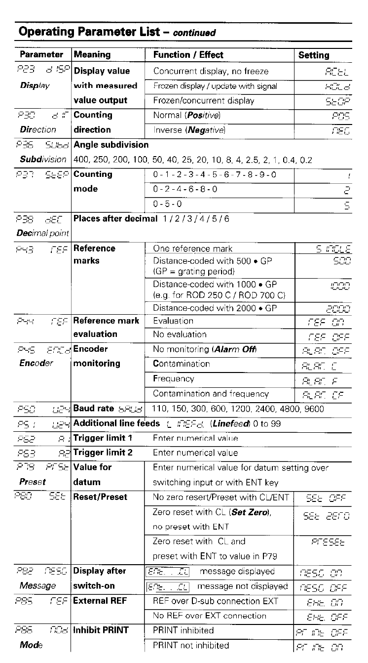
Operating Parameter List -
continued
Parameter
c: :s:
,- ,:c ;I;
Meaning Function I Effect Setting
Display value Concurrent display, no freeze ,c- c
JCcc
with measured Frozen display/update with signal ,-,,-,, -,
,i,L ,-,
value output Frozen/concurrent display -,,- ,-,r
Counting Normal (Posihve) 0°C
, ,-,-,
direction Inverse (Negative) :-;z c
Angle subdivision
400, 250, zoo, 100, 50, 40, 25, 20, 10, 8, 4, 2.5, 2, 1, 0.4, 0.2
Counting 0-1-2-3-4-5~6~7-8-9-0
mode 0-2-4-6-8-O 3
i
O-5-0 5
Places after decimal 1 / 2 / 3 / 4 / 5 / 6
~
Distance-coded with 1000
l
GP
Distance-coded with 2000. GP ,-,-,,-,c,
Reference mark Evaluation T&I ,-,,-,
,.,/
evaluation No evaluation
Encoder No monitoring (Alarm Off) ;I;; ;I;;; ;z;‘F;:
monitoring Contamination ;I;;-;I;;; ;I
Frequency :I;;-,c;;; p
Contamination and frequency ;I;;-:I;;; =;c
Baud rate hi~:,~ 110, 150, 300, 600, 1ZOO, 2400, 4800, 9600
Additional line feeds c ::?:F=;, (Linefeed) 0 to 99
Trigger limit 1 Enter numerical value
Trigger limit 2 Enter numerical value
Value for Enter numerical value for datum setting over
datum switching input or with ENT key
Reset/Preset No zero resertiPreset with CLiENT 5Fk fi;?:
Zero reset with CL iSetZero1, J;,;;;z I,
cc, ::
no preset with ENT
Zero reset with CL and ;I,;-;! 5;: ;=
preset with ENT to value in P79
Display after m;L message displayed : :;I5 !L, c:::
switch-on r;C message not displayed :-;~:,c 2;:;:
External REF REF over D-sub connection EXT ;:;.;,k, :-;:;’
No REF over EXT connection ;;;-;;=, c;;-;-
Inhibit PRINT PRINT inhibited ;:a;- ;;-;;- ; ;;-;.
PRINT not inhibited ,c,;- ;;b ;p-;