HEIDENHAIN ND 720 User manual

English (en)
12/2001
Position Display Units
for Milling Machines
User’s Manual
ND 720
ND 760
titel.pm6 07.11.2001, 10:342

HEIDENHAIN
Position display
(ND 720 only two axes)
D = Distance-to-go display
R+/ = Radius compensation
Numerical input
• Change the algebraic sign
• Call the last dialog
• Edit parameters in the
list of parameters
Call radius compensation
of the current tool
• Select special functions
• Page forward in the
list of special functions
• Cancel entry
• Reset the operating mode
• Zero the selected axis
(if activated in P80)
• Select parameters
CL plus two-digit number
Status display:
SCL = Scaling factor
->❘❘<- = Probing an edge /
centerline
R = Radius/diameter display
• Select datum 1 or 2
• Page backward in the list of
special functions
• Page backward in the list of
parameters
1 2 Datum 1 or 2
S T = Datum setting
R F = blinking:
Traverse the
reference points.
On continuously:
Reference points
have been traversed.
Inch = Display in inches
Select coordinate axes
(ND 720 only X and Y)
Select axis-specific operating parameters
• Confirm entry
• Page forward in the
list of parameters
Bateil1.pm6 07.11.2001, 10:362

Part I Operating Instructions
3
This manual is for the ND display units with the
following software numbers or higher:
ND 720 for two axes 246 271-07
ND 760 for three axes 246 271-07
About this manual
This manual is divided into two parts:
Part I: Operating Instructions
Fundamentals of positioning
ND functions
Part II: Installation an Specifications
Mounting the display unit on the machine
Description of operating parameters
Switching inputs, switching outputs
Part I Operating Instructions
Fun amentals 4
Switch-On, Traversing the Reference Marks 9
Datum Setting 10
Datum setting with the tool
Datum setting with the KT Edge Finder 3
Tool Compensation 20
Moving the Axes with Distance-To-Go 21
Bolt Hole Circles an Bolt Hole Circle Segments 23
Linear Hole Patterns 26
Working with a Scaling Factor 29
Error Messages 30
Part II
Installation an
Specifications Page 31
an following
Bateil1.pm6 07.11.2001, 10:363

4
Y
X
Z
+Y
+X
+Z
–Z –Y
–X
Datum or
origin
Graduation
Fundamentals
Fundamentals
You can skip this chapter if you are already familiar with
coordinate systems, incremental and absolute dimensions,
nominal positions, actual positions and distance-to-go.
Coor inate system
The Cartesian1) coordinate system is used to describe the geometry of
a workpiece. The Cartesian coordinate system consists of three
mutually perpendicular axes X, Y and Z. The point of intersection of
these axes is called the atum or origin of the coordinate system.
Think of the axes as scales with divisions (usually in millimeters) which
allow us to fix points in space referenced to the datum.
To determine positions on a workpiece, the coordinate system is
laid onto the workpiece.
The machine axes are parallel to the axes of the coordinate system.
The Z axis is normally the tool axis.
1) Named in honor of the French mathematician and philosopher
René Descartes ( 596 to 650)
Bateil1.pm6 07.11.2001, 10:364

5
Datum setting
The workpiece drawing is used as the basis for machining the
workpiece. To enable the dimensions in the drawing to be converted
into traverse distances of machine axes X, Y and Z, each drawing
dimension requires a datum or reference point on the workpiece
(since a position can only be defined in relationship to another
position).
The workpiece drawing always indicates one absolute datum (the
datum for absolute dimensions). However, it may contain additional
relative datums.
In the context of a numerical position display unit, datum setting
means bringing the workpiece and the tool into a defined position in
relation to each other and then setting the axis displays to the value
that corresponds to that position. This establishes a fixed relationship
between the actual positions of the axes and the displayed positions.
You can set 9 absolute datum points and store them in nonvolatile
memory.
Fundamentals
0
325
450
700
900
950
0
320
750
1225
300±0,1
0
150
-150
0
0
216,5 250
-250
-125
-216,5
0
-125
-216,5
-250
250
125
216,5
125
Relative
datum
Absolute
datum
Bateil1.pm6 07.11.2001, 10:365

6
Absolute workpiece positions
Each position on the workpiece is uniquely defined by its absolute
coordinates.
Example Absolute coordinates of position 1:
X = 0 mm
Y = 5 mm
Z = 0 mm
If you are working according to a workpiece drawing with absolute
dimensions, then you are moving the tool to the coordinates.
Y
X
Z
10
5
1
Fundamentals
1
Y
X
Z
10
510
10
1
2
Relative workpiece positions
A position can also be defined relative to the previous nominal
position. The datum for the dimension is then located at the previous
nominal position. Such coordinates are termed relative coor inates or
chain dimensions. Incremental coordinates are indicated by a
preceding I.
Example Relative coordinate of position 2 referenced to
position 1:
IX = 0 mm
IY = 0 mm
If you are working according to a workpiece drawing with incremental
dimensions, then you are moving the tool by the dimensions.
Sign for incremental imensioning
A relative dimension has a positive sign when the axis is moved in the
positive direction, and a negative sign when it is moved in the
negative direction.
Bateil1.pm6 07.11.2001, 10:366

7
Nominal position, actual position an istance-to-go
The position to which the tool is to move is called the nominal
position (
S
). The position at which the tool is actually located at any
given moment is called the actual position (
I
).
The distance from the nominal position to the actual position is called
the distance-to-go (
R
).
Sign for istance-to-go
When you are using the distance-to-go display, the nominal position
becomes the relative datum (display value 0). The distance-to-go is
therefore negative when the tool moves in the positive axis direction,
and positive when it moves in the negative axis direction.
Fundamentals
Y
X
Z
IS
R
Bateil1.pm6 07.11.2001, 10:367

8
Position enco ers
The position encoders on the machine convert the movements of the
machine axes into electrical signals. The ND display unit evaluates
these signals, determines the actual position of the machine axes and
displays the position as a numerical value.
If the power is interrupted, the relationship between the machine axis
positions and the calculated actual positions is lost. The reference
marks on the position encoders and the REF reference mark
evaluation feature enable the ND to quickly reestablish this
relationship again when the power is restored.
Reference marks
The scales of the position encoders contain one or more reference
marks. When a reference mark is crossed over, a signal is generated
which identifies that position as a reference point (scale datum =
machine datum).
When this reference mark is crossed over, the ND's reference mark
evaluation feature (REF) restores the relationship between axis slide
positions and display values which you last defined by setting the
datum. If the linear encoders have istance-co e reference marks,
you only need to move the machine axes a maximum of 20 mm to do
this.
Y
X
Z
Workpiece
Position-
encoder
Scale in Distance-coded
linear encoder reference marks
Reference marks
Fundamentals
Bateil1.pm6 07.11.2001, 10:368

9
Switch-On, Traversing the Reference Marks
ENT...CL
Turn on power (switch located on rear panel).
REF in status display starts blinking.
Confirm reference traverse mode. REF
remains on continuously. Decimal points start
blinking.
Cross over the reference marks in all axes in any
sequence. Each axis display becomes active
when its reference mark is crossed over.
0 è 1
ENT
Crossing over the reference marks stores the most recently defined
assignment of display values to axis slide positions for datum points
and 2 in nonvolatile memory.
Note that if you choose not to traverse the reference marks (by
clearing the dialog ENT ... CL with the CL key), this relationship will be
lost if the power is interrupted or when the unit is switched off.
Switch-On, Traversing the Reference Marks
If you wish to use multipoint axis error compensation you
must traverse the reference marks (see Multipoint axis error
compensation)!
Bateil1.pm6 07.11.2001, 10:369

10
Datum Setting
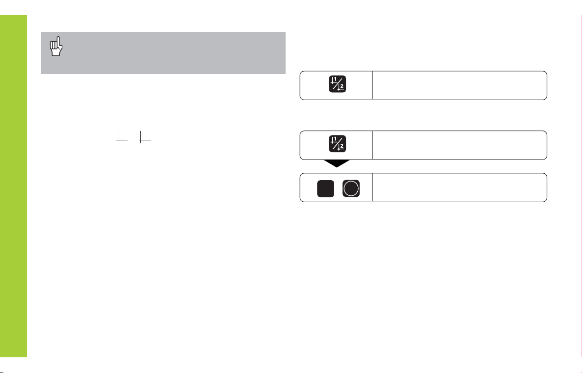
If you want to save the datum points in nonvolatile
memory, you must first cross over the reference
marks.
Press the datum key (d starts
blinking).
Datum Setting
In P70, you can select:
Two datum points: The selected datum point
is displayed via or 2
Nine datum points: The selected datum point
is displayed in the lowest axis via d to d9.
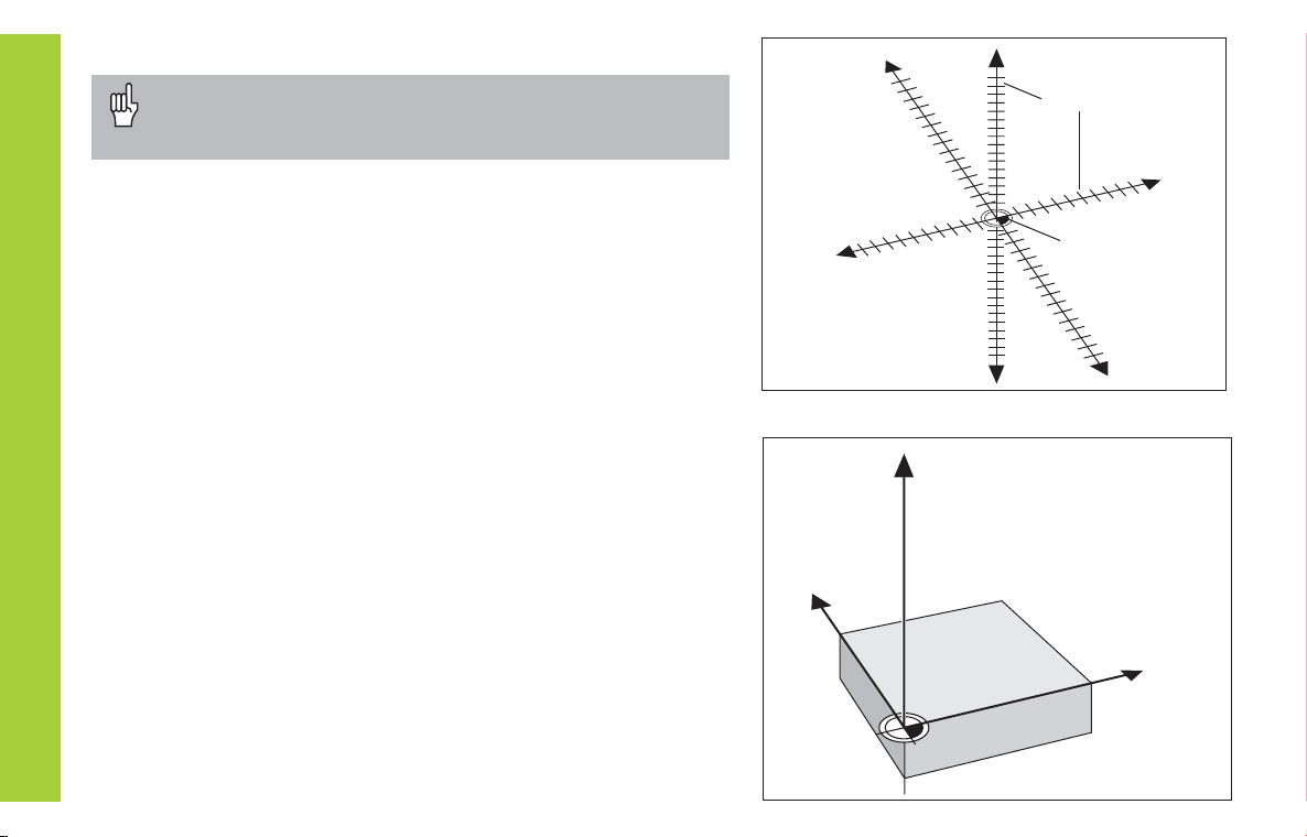
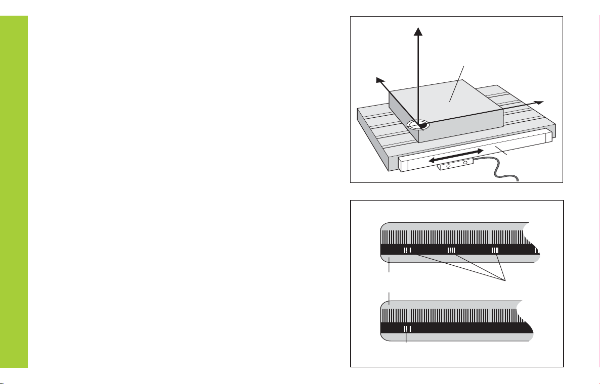
Touch the workpiece with the tool and then set the desired
datum (see example). You can also touch two edges and set
the centerline between them as a datum. The dimensions of
the tool used for this are automatically accounted for (see
Tool Compensation).
Probe the workpiece with the e ge fin er and then set the
desired datum. You can also probe two edges and set the
centerline between them as a datum, or touch the inside of a
circle and set the circle center as a datum (see examples).
The stylus radius and length are automatically accounted for
if they have been entered in parameters P25 and P26,
respectively (see Operating Parameters).
Enter a datum number ( to 9).
1
ENT
Only after crossing over the reference marks can you set
new datums or activate existing ones.
There are two ways to set datums:
To call a datum you have set, proceed as follows:
Select datum or 2.
You have set two datum points in P70:
You have set nine datum points in P70:
Bateil1.pm6 07.11.2001, 10:3610

11
Datum Setting
Select a datum number (see page 0).
Select the special functions.
SPEC
FCT
PROBE EDGE
ENT Confirm Probe edge.
X
Select X axis (if not already selected).
SET lights. The ❘<- symbol starts to blink.
Select the probing function.
PROBING
ENT
Confirm selection.
SPEC
FCT or
Y
X
2
1
Z
R=5mm
Datum setting with the tool
Example:
Working plane X / Y
Tool axis Z
Tool radius R = 5 mm
Axis sequence X Y Z
for datum setting
Bateil1.pm6 07.11.2001, 10:3611

12
Datum Setting
ZSelect the Z axis. SET lights.
The ❘<- status symbol starts blinking.
Touch the top of the workpiece with the
tool.
ENT
Z position is captured. SET edge is
shown briefly. SET starts blinking.
Retract the tool from the workpiece.
The ❘<- status symbol lights.
Enter the position value for the datum in
the Z axis.
0
ENT
After setting the datum, exit the probing
functions.
PROBE Z (appears only briefly)
SPEC
FCT
or
CL
1)
1)
1)
1)
1) only with ND 760
ENT Y position is captured. SET edge is
shown briefly. SET starts blinking.
Retract tool from workpiece.
The ❘<- status symbol lights.
Enter position value for the datum
in the Y axis. Tool radius is automatically
compensated.
0
ENT
ENT X position is captured. SET edge is
shown briefly. SET starts blinking.
Retract tool from workpiece.
The ❘<- status symbol lights.
Enter position value for the datum.
Tool radius is automatically
compensated.
0
Y
Select the Y axis. SET lights.
The ❘<- status symbol starts blinking.
ENT
Touch workpiece edge 2 with the tool.
PROBE Y (appears only briefly)
Touch workpiece edge 1 with the tool.
PROBE X (appears only briefly)
Bateil1.pm6 07.11.2001, 10:3612

13
Datum Setting
Datum setting with the T Edge Finder
The ND position display units provide the following probing functions:
PROBE EDGE Setting a workpiece edge as datum
PROBE MIDPOINT Setting a midpoint between two
workpiece edges as datum
PROBE CIRCLE Setting the center of a circle as datum
The probing functions are accessible in the SPEC FCT mode of
operation.
Before using the edge finder you must enter the stylus diameter and
length in parameters P25 and P26, respectively (see Operating
Parameters).
During all probing functions, the ND position display unit accounts for
the entered dimensions.
The PROBE EDGE, PROBE MIDPOINT and PROBE CIRCLE
functions are described on the following pages.
Bateil1.pm6 07.11.2001, 10:3613

14
Probing a workpiece e ge to fin a atum
The edge to be probed is parallel to the Y axis. You can probe edges
and surfaces as described below to set all the coordinates of a datum.
Datum Setting
Y
X
Z
X?
Select a datum number (see page 0).
Select the special functions.
SPEC
FCT
Select the probing function.
PROBING
ENT
Confirm the probing function.
SPEC
FCT
ENT
Confirm probe edge function.
PROBE EDGE
Bateil1.pm6 07.11.2001, 10:3614

15
Datum Setting
X
Select the X axis (if not already selected).
SET lights. The ❘< status symbol
starts blinking.
Move the edge finder to edge of workpiece until
indicator in edge finder lights. SET edge is
shown briefly. SET starts blinking. The ND
displays the position of the edge. The ❘< status
symbol lights.
Back the edge finder away from the workpiece.
5
2
Assign a position value to this edge, e.g. 52.
SPEC
FCT
Exit the probing function.
ENT
CL
or
PROBE X (appears only briefly)
Bateil1.pm6 07.11.2001, 10:3615

16
Probing workpiece e ges to fin a mi point atum
The edges to be probed run parallel to the Y axis.
Follow the procedure below for all midpoints between two edges.
Y
X
2
1
Z
M
X?
Datum Setting
Select the special functions.
SPEC
FCT
Select the probing function.
PROBING
ENT
Confirm the probing function.
SPEC
FCT or
Select a datum number (see page 0).
ANTASTEN MITTE Select the midpoint probing function.
PROBE EDGE
or
Bateil1.pm6 07.11.2001, 10:3616

17
Datum Setting
X
Select the X axis (if not already selected).
The ->❘❘<- status symbol starts blinking.
Move edge finder toward workpiece
edge 1 until the indicator in the edge
finder lights. Back edge finder away
from the workpiece.
Move edge finder toward workpiece
edge 2 until the indicator in the edge
finder lights. SET MIDPOINT is
shown briefly. SET begins to blink.
Back the edge finder away from the
workpiece. The ->❘❘<- symbol begins to
blink.
2
6
Set the position value for the midpoint
between the edges, e.g. 26.
Exit the probing functions.
ENT
SPEC
FCT
CL
or
1ST POS X (appears only briefly)
2ND POS X (appears only briefly)
ENT
Confirm the probe midpoint function.
SET lights.
PROBE MIDP.
Bateil1.pm6 07.11.2001, 10:3617

18
Probing the insi e of a circle to set its center as atum
To determine the circle center, the tool must probe four points. The
points to be probed are located in the X-Y plane.
Datum Setting
Select the special functions.
SPEC
FCT
Select the probing function.
PROBING
ENT Confirm the probing function.
SPEC
FCT or
Select a datum number (see page 0).
ANTASTEN MITTE Select the circle probing function.
PROBE CIRC.
or
Bateil1.pm6 07.11.2001, 10:3618

19
Datum Setting
Move edge finder toward position 1
until the indicator in the edge finder
lights. Back edge finder away from
workpiece.
Move edge finder toward position 2
until the indicator in the edge finder
lights. Back edge finder away from
workpiece.
2
6
Enter position value for the
X coordinate of circle center, e.g. 26.
CENTER Y is shown briefly. The SET
status display starts to blink in the Y
axis.
Exit the probing functions.
ENT
ENT
PROBE CIRC.
SPEC
FCT
CL
or
1ST POS X (appears only briefly)
2ND POS X (appears only briefly)
Confirm Probe circle.
Move edge finder toward position 3
until the indicator in the edge finder
lights. Back edge finder away from
workpiece.
3RD POS Y (appears only briefly)
Move edge finder toward
position 4 until the indicator in the
edge finder lights. CENTER X is
shown briefly. The SET status display
starts to blink in the X axis.
4TH POS Y (appears only briefly)
Enter position value for the Y coordinate
of circle center, e.g. 0.
0
ENT
Bateil1.pm6 07.11.2001, 10:3619

20
Tool Compensation
Tool Compensation
You can enter the axis, length and diameter of the current tool.
Select the special functions.
TOOL DIAM.
2
0
Enter the tool diameter, e.g. 20 mm,
and confirm with ENT.
TOOL AXIS
Z
Set the tool axis.
SPEC
FCT
ENT
TOOL DATA
ENT
Confirm tool data input mode.
Select tool data.
SPEC
FCT
TOOL LENGTH
0
ENT
5
TOOL AXIS
Exit the special functions.
SPEC
FCT or
CL
or
1)
1) only with ND 760
Enter the tool length, e.g. 50 mm,
and confirm with ENT.
Bateil1.pm6 07.11.2001, 10:3620
This manual suits for next models
1
Table of contents
Other HEIDENHAIN Monitor manuals

HEIDENHAIN
HEIDENHAIN VRZ 770 User manual

HEIDENHAIN
HEIDENHAIN ND 281B User manual

HEIDENHAIN
HEIDENHAIN ND 730 User manual

HEIDENHAIN
HEIDENHAIN ND 282B User manual

HEIDENHAIN
HEIDENHAIN ND 231 User manual

HEIDENHAIN
HEIDENHAIN ND 780 User manual

HEIDENHAIN
HEIDENHAIN BC 110BF User manual

HEIDENHAIN
HEIDENHAIN ND 710 User manual

HEIDENHAIN
HEIDENHAIN ND 261 User manual

HEIDENHAIN
HEIDENHAIN ND 730 User manual