manuals.online logo
Brands
  1. Home
  2. •
  3. Brands
  4. •
  5. HEIDENHAIN
  6. •
  7. Monitor
  8. •
  9. HEIDENHAIN VRZ 770 User manual

HEIDENHAIN VRZ 770 User manual

This manual suits for next models

1

Other HEIDENHAIN Monitor manuals

HEIDENHAIN ND 261 User manual

HEIDENHAIN

HEIDENHAIN ND 261 User manual

HEIDENHAIN ND 730 User manual

HEIDENHAIN

HEIDENHAIN ND 730 User manual

HEIDENHAIN ND 710 User manual

HEIDENHAIN

HEIDENHAIN ND 710 User manual

HEIDENHAIN ND 282B User manual

HEIDENHAIN

HEIDENHAIN ND 282B User manual

HEIDENHAIN ND 231 User manual

HEIDENHAIN

HEIDENHAIN ND 231 User manual

HEIDENHAIN BC 110BF User manual

HEIDENHAIN

HEIDENHAIN BC 110BF User manual

HEIDENHAIN ND 281B User manual

HEIDENHAIN

HEIDENHAIN ND 281B User manual

HEIDENHAIN ND 780 User manual

HEIDENHAIN

HEIDENHAIN ND 780 User manual

HEIDENHAIN VRZ 650 Instruction sheet

HEIDENHAIN

HEIDENHAIN VRZ 650 Instruction sheet

HEIDENHAIN ND 730 User manual

HEIDENHAIN

HEIDENHAIN ND 730 User manual

HEIDENHAIN ND 720 User manual

HEIDENHAIN

HEIDENHAIN ND 720 User manual

HEIDENHAIN BE 411F User manual

HEIDENHAIN

HEIDENHAIN BE 411F User manual

HEIDENHAIN ND 286 User manual

HEIDENHAIN

HEIDENHAIN ND 286 User manual

Popular Monitor manuals by other brands

Samsung ME32C user manual

Samsung

Samsung ME32C user manual

ViewSonic VA926-LED user guide

ViewSonic

ViewSonic VA926-LED user guide

Furuno Mu 120c Operator's manual

Furuno

Furuno Mu 120c Operator's manual

Asus VB171D - 17" LCD Monitor Service manual

Asus

Asus VB171D - 17" LCD Monitor Service manual

AOC 9GLR Technical specifications

AOC

AOC 9GLR Technical specifications

DMG RAFFAELLO manual

DMG

DMG RAFFAELLO manual

AOC LM720 - 17" Technical specifications

AOC

AOC LM720 - 17" Technical specifications

Sony Trinitron GDM-F500 Service manual

Sony

Sony Trinitron GDM-F500 Service manual

Memorex MT1701 user guide

Memorex

Memorex MT1701 user guide

ViewSonic VE510s-4 Service manual

ViewSonic

ViewSonic VE510s-4 Service manual

Farenheit T-1503CM instruction manual

Farenheit

Farenheit T-1503CM instruction manual

Ditel DINOS DN129/AT Quick installation guide

Ditel

Ditel DINOS DN129/AT Quick installation guide

Sony SDM-S51 Specifications

Sony

Sony SDM-S51 Specifications

Kenwood DMX1025BT quick start guide

Kenwood

Kenwood DMX1025BT quick start guide

Dell S2409WFP user guide

Dell

Dell S2409WFP user guide

EverFocus EN-7517E instruction manual

EverFocus

EverFocus EN-7517E instruction manual

Dell P3222QE user guide

Dell

Dell P3222QE user guide

Panasonic TH152UX1 - 152" PLASMA TV Service manual

Panasonic

Panasonic TH152UX1 - 152" PLASMA TV Service manual

manuals.online logo
manuals.online logoBrands
  • About & Mission
  • Contact us
  • Privacy Policy
  • Terms and Conditions

Copyright 2025 Manuals.Online. All Rights Reserved.

HEIDENHAIN
Betriebsanleitung
Operating Instructions
Mode d’emploi
VRZ 73Oj.770
Meßwertanzeigen für Drehmaschinen
Display Units for Lathes
Visualisations de totes pour tours
Inhaltsübersicht Seite
1. Lieferumfang 4
2. Anschlußmaße 5
3. Bedienelemente und Anzeigen
4. Aufstellung der Meßwertanzeige 8
5. Elektrische Anschlüsse 8
5.1 Schutzklasse
5.2 Anschluß der Meßsysteme :
5.3 Umschalten der Netz-
spannung 8
5.4 Netzanschluß 9
6. Einrichtfunktionen 10
6.1 Einstellen der Parameter 10
6.2 Parameter-Übersicht 12
6.3 Tabelle: Anzeigeschritt,
Teilungsperiode und Unter-
teilungsfaktoren 15
6.4 Parameter-Beschreibung 16
7. Externe Funktionen über
12polige Flanschdose
7.1 Pinbelegung
7.2 Pegel
7.3 Nullen X, Zo, Z
7.4 Nulldurchgangssignal
8. Fehlermeldungen
9. Hinweise für Betrieb und
Wartung
10. Technische Daten
19
19
19
20
20
21
22
23
Contents Page
7. ltems Supplied 4
2. Dimensions 5
3. Controls and Displays 6
4. Mounting the Display Unit 8
5. Electrical Connections 8
5.1 Protection 8
5.2 Connection to Encoders 8
5.3 Selection of Mains Voltage 8
5.4 Mains Connection 9
6. Setup Functions 70
6.7 Adjusting the Parameters IO
6.2 Parameter Ovetview 73
6.3 Table: Display Step, Grating
Period and Subdivision
Factors 15
6.4 Parameter Description 16
7. External Functions via 12-Pole
Flange Socket 19
7.7 Pin Assignment 19
7.2 Level 19
7.3 Set to Zero X Zo, Z 20
7.4 Zero Crossover Signal 20
8. Error Messages 21
9. lnstructions for Operation
and Maintenance 22
10. Technical Specifications 24
Sommaire Page
1. Objet de Ia fourniture 4
2. Dimensions 5
3. Elements de commande et de
visualisation 6
4. Mise en place du compteur c 8
5. Raccordements electriques 8
5.1 Classe de protection 8
5.2 Raccordement des systemes
de mesure 8
5.3 Selection de Ia tension
d’alimentation secteur 8
5.4 Raccordement au secteur 9
6. Fonctions pour Ia configuration 10
6.1 Parametrage 10
6.2 Liste des parametres 14
6.3 Tableau: Resolution d’affichage,
pas de Ia gravure et facteur
de subdivision 15
6.4 Description des parametres 16
7. Fonctions externes via I’embase
12 plots 19
7.1 Distribution des Plots 19
7.2 Niveaux 19
7.3 Remise a zero X, Zo, Z 20
7.4 Signal de a zer-0passage 20
8. Messages d’erreurs 21
9. Instructions pour I’utilisation
et Ia maintenance 22
10. Caracteristiques techniques 25
1. Lieferumfang
VRZ 730 für 2 Achsen bzw.
VRZ 770 für 3 Achsen
,Ersatzsicherung
,Netzkupplung (beigepackt)
,Stecker, 12polig (Id.-Nr. 20072003)
,Betriebsanleitung mit Parameterkarte
,Bedienungsanleitung ,,Lotse”
,Kontrollschein
auf Wunsch:
Netzkabel 2,7 m lang
1. Items Supplied 1. Objet de Ia fourniture
VRZ 730 for 2 axes or VRZ 730 pour 2 axes ou
VRZ 770 for 3 axes VRZ 770 pour 3 axes
.Replacement Fuse .Fusible de rechange
,Mains Connector (enclosed) Connecteur secteur (inclus)
.Connector 12-Pole (ld.-Nr 200 72003) .Connecteur 12 Plots (No. d’id. 20072003)
Opera ting lnstructions with Parameter ,Mode d’emploi avec carte des
Chart parametres
“Pilot” Opera ting Guide
1Certificate of lnspection
Optional:
.Mode d’utilisation “Pilote”
.Certificat de controle
sur demande:
Mains Cable 2.7 m (9 i?) long Gable secteur d’une longueur de 2.7 m
Gültigkeit
Diese Betriebsanleitung gilt für
VRZ 730/770 ab Software-Nummer:
VRZ 730: 246001.03
VRZ 770: 246001.03
Vakdity Validit6
These Operating lnstructions are valid Ce mode d’emploi est valable pour les
for VRZ 7301770 as of soffware number. VRZ 730/770 a partir du no. de soft:
VRZ 730: 246001.03 VRZ 730: 246001.03
VRZ 770: 246001.03 VRZ 770: 246001.03
Bescheinigung des Herstellers
Hiermit wird bescheinigt, daß dieses
Gerät in Ubereinstimmung mit den
Bestimmungen der AmtsblVfg 1046/
1984 funkentstört ist.
Der Deutschen Bundespost wurde das
Inverkehrbringen dieses Gerätes,,ange-
zeigt und die Berechtigung zur Uber-
Prüfung der Serie auf Einhaltung der
Bestimmungen eingeräumt.
Hinweis:
Wird vom Betreiber das Gerät in eine
Anlage eingefügt, muß die gesamte
Anlage den obigen Bestimmungen
genügen.
4
ManufacturerS certificate
We hereby certiq that this unit is
radioshielded in accordance with the
West German oficial register decree
1046/1984.
The West German postal authorities
have been notified of the issuance of
this unit and have been granted admis-
sion for examination of the series
regarding compliance with the regula-
tions.
Information:
lf the unit is incorporated by the user
into an instalation then the complete
installation must comply with the above
requirements.
Attestation du constructeur
Par Ia presente nous certifions que
I’appareil ci-dessus est anti-parasite
conformement aux dispositions du
decret du bulletin officiel 1046/1984.
L’administration allemande des Postes a
etc informee de Ia mise en circulation
de cet appareil et est autorisee a veri-
fier Ia Serie en ce qui concerne Ia con-
formite aux stipulations.
Remarque:
Si I’utilisateur integre I’appareil dans une
installation, celle-ci doit se conformer a
Ia totalite des stipulations ci-dessus.
2. Anschlußmaße mm/Zoll 2. Dimensions mmjinch 2. Dimensions mm/pouce
c
i:
-
Ansicht A
vvlEeWAA
5
3. Bedienelemente und Anzeigen 3. Controls and Displays
VRZ 730 (2 Achsen) VRZ 730 (2 axes)
VRZ 770 (3 Achsen) VRZ 770 (3 axes)
3. Elements de commande et de
visualisation
VRZ 730 (2 axes)
VRZ 770 (3 axes)
Istwert-/Eingabe-Anzeigen
Actual Positionflnput Display
Affichage de Ia Valeur nominale/
d’introduction I
Achsanzeige-Dioden
Axis Display Diodes
Diodes d’affichage d’axe
I
Achsanwahl
Axis Selection
c
:hoix de I’axe Zahlen-Eingabe
Numerital Entry
Introduction de valeurs
Radius-/Durchmesser-Anwahl
RadiuslDiameter Selection
q/I
9 Choix du rayon/Choix du diametre
/
Summenanzeine (Z + Zo)
Sum Display (Z < Zo)
Visualisation de sommes (Z + Zo)
Referenzmarken-Auswertung REF
REF Reference Mark Evaluation
Exploitation de marques de reference REF
;fgY,~
: mm/inch-Rechner
tskd HEIDENHAIN
(über Betriebsparameter PIO)
c9
:: -ke y: mmlinch-calcula tor
(via Operational Parameter PIO)
Tauche ::
19 : calculateur mm/pouce
(par Ie parametre PIO)
Restweg ,,Fahren auf Null”
Distance-to-Go “Countdown Positioning”
Course restante “Deplacement vers Zero”
l
Eingabe Iöschen/Parameter anwählen
Clear EntryfAddress Parameters
Annulation de I’entree/Selection du parametre
Achsanzeige-Nullurig (über Betriebsparameter P20)
Axis Display Reset (via Operating Parameter P20)
Remise a zer-0 des axes (par Ie parametre P20)
6
TypenschildTypenschild
15 Plate15 Plate
Plaque signaletique (
Plaque signaletique 4
+
1+
\
Spannungswähler mit
Spannungswähler mit
NetzsicherungNetzsicherung
Voltage Selector withVoltage Selector with
Mains FuseMains Fuse
Selecteur de tension avecSelecteur de tension avec
fusible secteurfusible secteur
JllII
--I I l
-tk
t
I /
Eingänge für Meßsysteme X
Inputs for Encoders zo
Entrees pour systemes de mesure Z
Netzeingang
Mains Input
Embase secteur
iqetzschalter
I
=ower Switch
(2ommutateur secteur
4. Aufstellung der Meßwertanzeige
Der VRZ hat ein Gehäuse aus Alu-
minium-Druckguß. M5-Gewindebohrun-
gen ermöglichen eine Befestigung auf
Tischen oder Konsolen (siehe An-
schlußmaße).
5. Elektrische Anschlüsse
ACHTUNG: Unter Spannung keine
Stecker lösen oder verbinden.
5.1
Schutzklasse
Die Frontplatten und Bedientafel der
Meßwertanzeige sind spritzwasserge-
schützt. Die VRZ 730/770 entsprechen
Schutzklasse I der VDE-Bestimmungen
VDE 0411 und sind gemäß DIN 57411
Teil l/VDE 0411 Teil 1 ,,Schutzmaßnah-
men für elektronische Meßgeräte”
gebaut und geprüft. Um diesen Zu-
stand zu erhalten und einen gefahrlosen
Betrieb sicherzustellen, muß der An-
wender die Hinweise und Warnver-
merke beachten, die in dieser Betriebs-
anleitung enthalten sind.
5.2
Anschluß der Meßsysteme
An die VRZ 7301770 sind alle Längen-
meßsysteme mit 4,10, 20, 40, 100 oder
200 um Teilungsperiode und normalen
bzw. abstandscodierten Referenzmarken
sowie HEIDENHAIN-Drehgeber ohne
eingebaute Digitalisierungs-Elektronik
anschließbar.
Die Elektronik der Meßwertanzeige wird
über Parameter an die Teilungsperiode
des angeschlossenen Meßsystems an-
gepaßt (siehe Abschnitt 6.3).
5.3
Umschalten der Netzspannung
Die VRZ sind vom Werk aus auf 220 V
eingestellt. Folgende Spannungsbe-
reiche sind möglich:
Stellung 1: 100 V (-15 %) 1IO V
(+lO %) Sicherung T 0,315 A
Stellung 2: 120 V (-15 %) 130 V
(+lO %) Sicherung T 0,315 A
Stellung 3: 220 V (-15 %) 240 V
(+lO O/o)Sicherung T 0,160 A
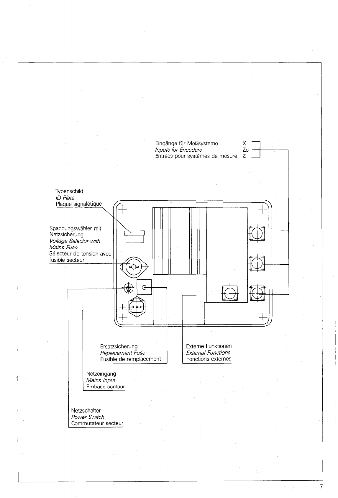
Nach Herausnehmen des Netzsiche-
rungshalters kann der Spannungsum-
schalter mit einer Münze auf den
gewünschten Spannungsbereich einge-
stellt werden. Danach ist der Netzsiche-
rungshalter mit der entsprechenden
Sicherung wieder einzusetzen:
Je 1 Ersatzsicherung befindet sich im
Sicherungskästchen neben dem Netz-
schalter.
Hinweise vor dem Einschalten des
Gerätes:
1. Vor dem Einschalten ist sicherzustel-
len, daß die am Gerät eingestellte
Betriebsspannung und die Netzspan-
nung übereinstimmen.
2. Wenn dieses Gerät über einen Spar-
transformator aus einem Netz höherer
Spannung betrieben werden soll, ist
sicherzustellen, daß der Fußpunkt des
Transformators mit dem Mittelleiter des
Netzes verbunden ist.
8
4. Mounting the Display Unit
The VRZ has a die-cast aluminium
Chassis. M5 threaded holes permit the
unit to be fastened to tables or con-
soles (sec dimensions).
5. Eiectrical Connections
CAUTION: DO not engage or disen-
gage any connector while under
power
5.1
Protection
Front Panel and control Panel of the
display unit are splashwater-proof The
VRZ 7301770 Display Units have been
produced and checked as per German
Standard DIN 57411 patt IlVDE 0477
“Protective Measures for Electronie
Measuring Equipment’: Please do not
neglect to carefuly comply with all
instructions and notes contained here-
in.
5.2
Connection to Encoders
All linear encoders with grating periods
of 4, IO, 20, 40, 100 or 200 ,um and
normal or distance-coded reference
marks as weil as HEIDENHAIN rotary
encoders without incorporated digitiz-
ing electronics are adaptable to the
VRZ 7301770.
The display unit electronics are adapt-
ed via Parameter to the grating period
of the connected encoder (sec section
6.3).
5.3
Selection of Mains Voltage
The VRZ are set in the factory to 220 V
The folowing voltage ranges are
possible
Position 1: 100 V (-15 %) 110 V
(+lO %) fuse T 0.315 A
Position 2: 120 V (- 15 %) 130 V
(+lO %) fuse T 0.315 A
Position 3: 220 V (-15 %) 240 V
(+lO %) fuse T 0.160 A
To switch voltage range remove fuse
holder and adjust voltage selector to
the desired rating by means of a coin.
Insert appropriate fuse in the mains
fuse holder
One replacement fuse for each rating is
provided in the fuse compattment next
to the mains switch.
lnstructions Prior to unit switch-on:
1.Please insure before switch-on that
the voltage rating corresponds to the
mains supply
2. lf this unit is to be operated via an
autotransformer from a mains supply of
higher voltage, it must be ensured that
the low end of the transformer is con-
nected to the neutral wire of the mains
outlet.
4. Mise en place du compteur
Le compteur est dans un boitier en alu-
minium maule sous Pression. Des per-
cages taraudes M5 permettent une
fixation sur des tables ou des consoles
(voir Dimensions).
5. Raccordements electriques
ATTENTION: Ne pas brancher ni
debrancher de connecteur, I’appareil
etant sous tension.
5.1
Classe de protection
La face avant et Ie tableau de com-
mande du compteur sont proteges
contre les projections d’eau. Les comp-
teurs VRZ 730/770 sont conformes a Ia
classe de protection I des prescriptions
VDE 0411 et sont fabriques et controles
suivant Ia norme DIN 57411 Partie l/
VDE 0411 Partie 1 “Mesures de protec-
tions pour les appareils electroniques
de.mesure”. Pour conserver cet etat et
assurer un fonctionnement sans danger,
I’utilisateur doit suivre les remarques et
mises en garde contenues dans ce
mode d’emploi.
5.2
Raccordement des systemes de
mesure
Les VRZ 730/770 peuvent etre raccor-
des a tous les systemes de mesure
avec 4,lO. 20, 40,100 ou 200 um de
Periode de division et marques de refe-
rence normales ou a distance codee
ainsi que tous les codeurs rotatifs
HEIDENHAIN sans etage de mise en
forme des impulsions.
L’electronique des compteurs est adap-
tee par des parametres aux periodes de
division des systemes de mesure rac-
cordes (voir Paragraphe 6.3).
5.3
Selection de Ia tension d’alimenta-
tion secteur
Les compteurs sont regles a I’usine sur
220 V. Les gammes de tensions sui-
vantes sont possibles:
Position 1: 100 V (-15 %) 110 V
(110 %) Fusible T 0,315 A
Position 2: 120 V (-15 O/o) 130 V
(+lO %) Fusible T 0,315 A
Position 3: 220 V (-15 %) 240 V
(+lO %) Fusible T 0,160 A
Apres avoir retire Ie support-fusible, Ie
selecteur de tension peut etre posi-
tionne sur Ia plage de tension desiree.
Ensuite Ie support-fusible avec Ie
fusible correspondant peut etre remis
en place. Un fusible de rechange se
trouve dans Ia boite a fusibles situee a
tote du commutateur secteur.
Remarques concernant Ia mise sous
tension de I’appareil:
1. Avant Ia mise sous tension de I’ap-
pareil, verifier que Ia tension de Service
selectionnee sur I’appareil est identique
a Ia tension du secteur.
2. Si cet appareil est alimente par un
auto-transformateur, s’assurer que Ie
Point commun du transformateur est
connecte au neutre du secteur.
Umschalten der Netzspannung Auswechseln der Netzsicherung
Selecting the Mains Voltage Exchanging the Mains Fuse
SBlection de I’alimentation secteur Remplacement du fusible
Ersatzsicherungen T 0,315 A und T 0.16 A
T 0.315 A and T 0.16 A replacement fuses
fusibles de rechange T 0,315 A et 0.16 A
5.4
NetzanschluR
Die beigepackte Netzkupplung ist mit
einem Netzkabel zu verdrahten (kom-
plettes Netzkabel auf Wunsch). Nach
Einstecken der Netzkupplung in die
Netzdose ist der Sicherungsbtigel
niederzudrticken.
5.4
Mains Connection
Wire separate mains coupling to a
mains cable (complete mains cable
available as option). Push clip down
after inserting mains coupling into
mains socket of counter
5.4
Raccordement au secteur
Le connecteur secteur fourni est a rac-
corder a un cable secteur (cable com-
plet sur demande). Apres avoir enfonce
la prise dans I’embase secteur rabattre
le verrou de securite.
Verdrahtung der Netzkupplung
Wiring the Mains Coupling
Csblage de la fiche de raccordement secteur
ACHTUNG!
CAUTION!
ATTENTION!
Netzanschlul3 an Kontakten 3 2
Mains connection at contacts
Raccordement secteur aux contacts
Schutzerde an
Protective ground at
Terre de protection a
0
&
werden. Die Schutzwirkung darf nicht
Hinweis
durch eine Verlangerungsleitung ohne
Schutzleiter aufgehoben werden.
Jegliche Unterbrechung des Schutz-
Der Netzstecker darf nur in eine Steck-
leiters innerhalb oder aul3erhalb des
Gerates oder Losen des Schutzleiter-
dose mit Schutzkontakt eingefiihrt
anschlusses kann dazu fuhren, da8 das
Gerat gefahrbringend wird. Absichtliche
Unterbrechung ist nicht zulassig.
tact. The protective effect must not be
Please note
cancelled by an extension lead without
a grounded connector
Any interruption of the grounded con-
ductor either inside or outside of the
The mains connector may only be
unit or disconnection of the grounded
conductor can render the equipment
potentially dangerous. Any intentional
inserted into a socket with ground con-
break is impermissible.
avec mise a la terre. La protection elec-
trique ne doit pas etre alteree par
Remarques
I’emploi d’un cable prolongateur sans
conducteur de terre.
Toute interruption de la liaison a la terre
a I’interieur ou a I’exterieur de I’appareil
La fiche de raccordement secteur ne
peut rendre celui-ci electriquement
dangereux. Une interruption intention-
doit etre raccordee qu’a une embase
nelle n’est pas admissible.
6. Einrichtfunktionen
6.1
Einstellen der Parameter
Die Meßwertanzeige verfügt über netz-
ausfallsichere Betriebsparameter, die
nach dem Einschalten sofort wirksam
sind.
Durch qleichzeitiaes Betätiaen von zwei
Tasten - zuerst Taste
q
und dazu
eine Zifferntaste (
0 8 bei Parameter
PO0 bis PO9 oder
q
bei Parameter
Pl0 bis P20) - wird die Betriebsart
,,Parameter-Eingabe” angewählt,
In der X-Anzeige erscheint folgende
Anzeige: PO- oder Pl-. Durch Eingabe
einer weiteren Ziffer von 0 bis 9 wird
der entsprechende Parameter ange-
wählt.
6. Set-Up Functions
Adjusting th~e Parameters
6.1
The Display Unit features non-volatile
operating Parameters which are imme-
diately effective afier switch-on.
To select “parameter input” 0peratin.o
mode press and hold the
q
key and
then press a numerical key (m for
Parameters PO0 to PO9 or m for
parameters PI0 to PZO).
‘Either PO- or Pl- appears in the X dis-
play The corresponding Parameter is
Chosen by entering a further number
from 0 to 9.
Anzeigebeispiel für die X-Achse bei angewählter Zo-Achse:
Display example for the X axis when Zo axis has been selected:
Exemple d’affichage pour I’axe X en cas de choix de I’axe Zo:
Parameter No. X A2~~“““’
Parameter-Nr.
No. de parametre No. de I’axe
0: Parameter allgemein
general Parameter
parametre general
1: Parameter X-Achse
X axis Parameter
parametre de I’axe X
2: Parameter Zo-Achse
Zo axis Parameter
parametre de I’axe Zo
3: Parameter Z-Achse
Z axis Parameter
parametre de I’axe Z
nn n
Mit den Achstasten IX], Iz,] und Iz]
werden die Achsnummer und die Para-
meter der entsprechenden Achse ange-
wählt. Nicht achsspezifische Parameter
sind durch eine ,,0” gekennzeichnet
(Z.B. P10.0 mm/inch Umschaltung). In
der Z-Anzeige (VRZ 730) bzw. in der
Zo-Anzeige (VRZ 770) erscheint der
Wert des Parameters.
Durch Betätigen der u -Taste kann
der Parameter-Wert verändert werden.
Es werden dabei feste Tabellenwerte
nacheinander angewählt.
Eine Ausnahme bilden die Parameter
P07, Pl3 und P14. Die Werteingabe
bzw. Wertänderung erfolgt direkt über
die Zehnertastatur.
Mit der Taste @ wird die Parameter-
0
Eingabe abgeschlossen und der Para-
meter-wert in den Speicher übernom-
men.
Danach werden die aktuellen Meßwerte
wieder angezeigt.
The axis numbers and the Parameters
of the corresponding axis are selected
with the
q
, B and 12] axis keys.
Parameters which are not specific to a
cen’ain axis are marked with a “0” (e.g.
PIO.0 mmlinch selection). The value of
the Parameter appears in the Z-display
(VRZ 7301 or the Zo-displav (VRZ 770).
The Parameter value tan be changed
by pressing the
q
key Fixed table
values are then selected consecutively
An exception are the Parameters P07,
Pl3 and P74. Values are entered or
changed directly via numeric keys.
Parameter entrv is concluded with the
q
key and the Parameter value is
transferred to memory
Afierwards the current measured
values are displa yed again.
6. Fonctions pour Ia configuration
6.1
Paramktrage
Le compteur dispose de parametres de
fonctions non volatiles, qui sont effectifs
des Ia validation. Pour selectionner Ie
mode “entree de parametre” il faut
appuyer sur Ia tauche m et Ia tauche
d’un Chiffre (0 pour les parametres
PO0 a PO9 et 0 pour les parametres
Pl0 a P20).
Sur I’affichage de I’axe X apparait PO-
ou Pl-. Si I’on entre un Chiffre de 0 a 9,
Ie parametre correspondant sera selec-
tionne.
Les numeros d’axe et les parametres
des axes correspondants sont selec-
tionnes par les touches d’axe
q
, lo]
et 2
Cl Les parametres qui ne sont pas
specifiques a un axe precis sont mate-
rialises par un “0” (ex. P10.0 commuta-
tion mm/pouce).Dans Ia tauche d’axe Z
(VRZ 730) or dans Ia tauche d’axe Zo
(VRZ 770) Ia Valeur du parametre appa-
rait.
La Valeur du parametre peut etre modi-
fiee parl’action sur Ia tauche
q
Des
valeurs fixes de tableau sont ensuite
choisies consecutivement.
Les parametres P07, Pl3 et Pl4 repre-
sentent une exception. Les entrees et
modifications de valeurs sont possibles
directement oar Ie clavier numeriaue.
Par Ia tauche @, on conclut I’entree
0
des parametres. La Valeur du parametre
est transferee dans Ia memoire.
Les totes en cours sont ensuite de
nouveau affichees.
10
Grundsätzliche Vorgehensweise, gezeigt an Parameter PO4 (Teilungsperiode) und Parameter Pl0 (mm/inch-Umschaltung)
Basic procedure, shown with Parameter PO4 (grating periodl and Parameter PI0 (mmlinch selection)
Procedure de base montre sur Ie parametre PO4 (pas de Ia gravure) et Ie parametre Pl0 (commutation mm/pouce)
Parameter PO4
(achsabhängiger Parameter)
Parameter PO4
(axis-dependent parametetj
Parametre PO4
(dependant de I’axe)
Eingabe
Keying sequence
Entree
XIpo4.1)
Zr----Z!
--
Parameter Pl0
(achsunabhängiger Parameter)
Parameter Pl0
(axis-independent parameterj
Parametre Pl0
(independant de I’axe) “1
Eingabe
Keying sequence
Entree
IU
XI
I
XIp10.0
z/
.-------------
I
CE drücken und halten, null bzw. eins eingeben.
Eintritt in den Parameter-Betrieb.
Press and hold CE, enter zero or one.
Ent/y into Parameter Operation.
Appuyer sur CE et maintenir appuye,
introduire 0 ou 1.
Entree dans Ie mode parametre.
Anzeige des Betriebsparameters.’
Display of operating Parameter
Affichage des parametres d’utilisation.
Achsanwahl (notwendig nur bei achsabhängige1
Parametern).
Axis selection (necessary only with axis-
dependent Parameters).
Choix de I’axe (pour parametres dependant de
I’axe imperatif).
Status-Wechsel: setzt der Reihe nach Tabellen-
werte in die Z-Anzeige.
Status Change: sets table values consecutively
into the Z display.
Changement de Status: indique successivement
les valeurs dans I’affichage Z.
Übernahme in den Meßwertanzeige-Speicher.
Die Meßwertanzeige zeigt die Positionswerte
wieder an.
Transfer to disptay unit memory
Display unit displa ys Position values again.
Prise en campte dans Ia memoire du compteur.
Le compteur affiche a nouveau Ia Valeur de Ia
Position.
11