HEIDENHAIN ND 730 User manual

English (en)
10/2002
Position Display Units
for Lathes
User’s Manual
ND 730
ND 770
titel.pm6 21.07.2004, 08:342

HEIDENHAIN
Position display
(ND 730 only two axes)
∆= Distance-to-go
R = Radius/diameter
display
Numericalinput
• Changealgebraicsign
• Calllastdialog
• Change parameters
in the parameter list
Select radius/diameter display
in X axis
• Select special functions
• Page forward in the list of
specialfunctions
• Cancel entry
• Reset operating mode
• Zero the selected axis
(if activated via P 80)
• Select parameter:
CL plus two-digit number
Status display:
SCL = Scaling factor
SET = Setdatum
REF = Blinking:
Traverse the
referencepoints
On continuously:
Reference points have
been traversed
Inch= Inch display • Confirm entry
• Page forward
in the parameter list
T = Selectedtool
• Toolcompensation
• Page backward in the list of
specialfunctions
• Page backward in the list of
parameters
• Select coordinate axes
(ND 730 only X and Z)
• Select axis-specific operating parameters
730_770t1.pm6 21.07.2004, 08:352

Part I Operating Instructions
Fundamentals 4
Switch-On, Traversing the Reference Marks 10
Selecting Radius or Diameter Display 11
Separate Value/Sum Display
(only ND 770) 12
Datum Setting 13
Setting the absolute workpiece datum 13
Entering tool data (relative datums) 14
HoldingPositions 15
Moving theAxes with Distance-To-Go 17
Taper Calculator 19
Error Messages 23
Part II Page 25
Installation and Specifications and following
Part I Operating Instructions
3
This manual is for ND display units with the following
software numbers or higher:
ND 730 for two axes 246 271-07
ND 770 for three axes 246 271-07
About this manual
This manual is divided into two parts:
Part I: OperatingInstructions:
• Fundamentals of positioning
• ND functions
Part II: InstallationandSpecifications:
• Mounting the display unit on the machine
• Description of operating parameters
730_770t1.pm6 21.07.2004, 08:353

Fundamentals
4
+Y
+X
+Z
–Z –Y
–X
Z
X
Fundamentals
You can skip this chapter if you are already familiar with
coordinate systems, incremental and absolute dimensions,
nominal positions, actual positions and distance-to-go!
1) Named in honor of the French mathematician and philosopher
René Descartes (1596 to 1650)
Datumor
origin
Graduation
Coordinate system
To describe the geometry of a workpiece, a rectangular or
Cartesian*
coordinate system is used. The Cartesian coordinate system consists
of three mutually perpendicular axes X, Y and Z. The point of
intersection of these axes is called the datum or origin of the
coordinate system.
Think of the axes as scales with divisions (usually in millimeters) that
allow us to fix points in space referenced to the datum.
To determine positions on a workpiece, the coordinate system is
“laid” onto the workpiece.
With lathe work (i.e. rotationally symmetrical workpieces), the Z axis
moves along the axis of rotation, and the X axis moves in the direction
of the radius or diameter. The Y axis can be disregarded since it would
always have the same values as the X axis.
730_770t1.pm6 21.07.2004, 08:354

Fundamentals
5
Cross slide, saddle and top slide
On conventional lathes, the tool is mounted on a slide that moves in
the direction of the X axis (the cross slide) and in the direction of the Z
axis (the saddle).
Most lathes have a top slide above the saddle. The top slide moves in
Z axis direction and is designated Zo.
Z
Z
O
X
+Z
+X
+Z
O
730_770t1.pm6 21.07.2004, 08:355

Fundamentals
6
Z
X
10 5
3530
Datum setting
The workpiece drawing is used as the basis for machining the
workpiece. To enable the dimensions in the drawing to be converted
into traverse distances of machine axes X and Z, each drawing
dimension requires a datum or reference point on the workpiece
(since a position can only be defined in relationship to another
position).
The workpiece drawing always indicates one absolute datum (the
datum for absolute dimensions). However, it may contain additional,
relative datums.
In the context of a numerical position display unit,
datum setting
means bringing the workpiece and the tool into a defined position in
relation to each other and then setting the axis displays to the value
which corresponds to that position. This establishes a fixed
relationship between the actual positions of the axes and the
displayed positions.
With the ND, you can set one absolute datum point and as many as
9 relative datum points (tool datums), and store them in nonvolatile
memory.
Absolute
datum
Relative
datum
730_770t1.pm6 21.07.2004, 08:356

Fundamentals
7
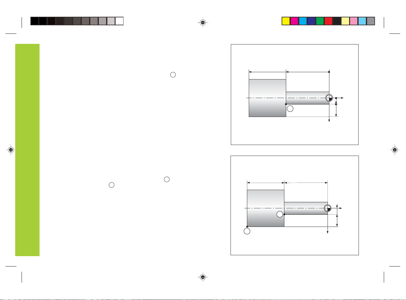
Nominalposition,actualpositionanddistance-to-go
The positions to which the tool is to move are called the nominal
positions (
S
). The position at which the tool is actually located at any
given moment is called the actual position (
I
).
The distance from the nominal position to the actual position is called
the distance-to-go (
R
).
Signfordistance-to-go
When you are using the distance-to-go display, the nominal position
becomes the relative datum (display value 0). The distance-to-go is
therefore negative when you move in the positive axis direction, and
positive when you move in the negative axis direction.
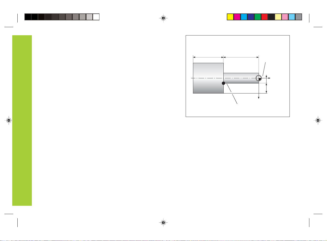
Tooldatums(toolcompensation)
Your display unit should show you the absolute position of the
workpiece, regardless of the length and shape of the particular tool
being used. For this reason you must determine the tool data and
enter it. First touch the workpiece with the cutting edge of the tool
and then enter the associated display value for that position.
You can enter tool data for up to 9 tools. When you have set the
absolute workpiece datum for a new workpiece, all tool data (= relative
datum points) are referenced to the new workpiece datum.
IS
Z
X
R
T1 T2 T3
730_770t1.pm6 21.07.2004, 08:357

Fundamentals
8
Z
X
15
5
35
65
1
0
Absoluteworkpiecepositions
Each position on the workpiece is uniquely defined by its absolute
coordinates.
Example Absolute coordinates of position
1
:
X = 5 mm
Z = –35 mm
If you are working according to a workpiece drawing with absolute
dimensions, you are moving the tool to the coordinates.
Z
X
1
10 5
3530
2
Relative workpiece positions
A position can also be defined relative to the previous nominal
position. The datum for the dimension is then located at the previous
nominal position. Such coordinates are termed relative coordinates or
chain dimensions. Incremental coordinates are indicated by a
preceding I.
Example Relative coordinate of position referenced to
position :
IX= 10 mm
IZ = –30 mm
If you are working according to a workpiece drawing with incremental
dimensions, you are moving the tool by the dimensions.
Signforincrementaldimensioning
A relative dimension has a positive sign when the axis is moved in the
positive direction, and a negative sign when it is moved in the
negative direction.
2
1
730_770t1.pm6 21.07.2004, 08:358

Fundamentals
9
Z
Positionencoders
The position encoders on the machine convert the movements of the
machine axes into electrical signals. The ND display unit evaluates
these signals, determines the actual position of the machine axes and
displays the position as a numerical value.
If the power is interrupted, the relationship between the machine axis
position and the calculated actual position is lost. The reference marks
on the position encoders and the REF reference mark evaluation
feature enable the ND to quickly re-establish this relationship again
when the power is restored.
Workpiece
Reference marks
The scales of the position encoders contain one or more reference
marks. When a reference mark is crossed over, a signal is generated
identifying that position as a reference point (scale datum = machine
datum).
When these reference points are crossed over, the ND's reference
mark evaluation feature restores the relationship between axis slide
positions and display values as you last defined it by setting the
datum. If the linear encoders have distance-coded reference marks,
you need only move the machine axes a maximum of 20 mm to
restore the datum.
Scale in linear
encoder
Reference mark
Distance-coded
reference marks
Encoder
730_770t1.pm6 21.07.2004, 08:359

10
Switch-On,Traversing the ReferenceMarks
ENT ... CL
ENT
Crossing over the reference marks stores the last relationship
between axis slide positions and display values for all datum points in
nonvolatile memory.
Note that if you choose not to cross over the reference marks (by
clearing the dialog ENT ... CL with the CL key), this relationship will be
lost if the power is switched off or otherwise interrupted!
Cross over the reference marks in all axes (in any
sequence). Each axis display becomes active when
its reference mark is crossed over.
Turn on the power (switch located on rear panel).
REF starts blinking in the status display.
0è1
Switch-On, Traversing the Reference Marks
You must cross over the reference marks if you want to use
the multipoint axis error compensation function.
(See “Multipoint Axis Error Compensation”)
Confirm reference traverse mode. REF remains
on continuously. Decimal points start blinking.
730_770t2.pm6 21.07.2004, 08:3610

11
Selecting Radius or Diameter Display
Your ND can display positions in the cross slide as a diameter or as a
radius. Drawings of lathe parts usually indicate diameters. When you
are turning the part, however, you infeed the tool in the cross slide
axis in radius values.
Example: Radius display position X = 20 mm
Diameter display position X = 40 mm
To switch the display:
¬ Press
When radius display for the X axis is selected, R lights up.
When diameter display is selected, R goes out.
Selecting Radius or Diameter Display
20
Z
1
X
¯40
730_770t2.pm6 21.07.2004, 08:3611

12
SeparateValue/SumDisplay(ND770only)
Separate value display
In this mode the positions of the saddle and top slide are displayed
separately. The position displays are referenced to the datum points
that you set for the Zo and Z axes. When an axis slide moves, only the
position display for that axis changes.
Sumdisplay
In this mode the position values of both axis slides are added together.
The sum display shows the absolute position of the tool, referenced to
the workpiece datum.
Example Separate value display: Z = +25.000 mm
Zo = +15.000 mm
Sum display: ZS= +40.000 mm
The sum display will only show correct values if the actual
position values of both axis slides were correctly added and
entered (with sign) when setting the datum for the “sum.”
To switch the display
➤Sum display: Press the keys Zo and Z at the same time.
➤Separate value display: Press the key Zo.
When the ND 770 displays sums, the Zo display is switched
off.
Separate Value/Sum Display (ND 770 only)
Ð10
40
0 +10 +25
Z
Z
0 +15
Z0
Z
Z0
730_770t2.pm6 21.07.2004, 08:3612

13
Z
ENT
0
Datum Setting
Z
Z=0
DatumSetting
•If you want datum points to be stored in nonvolatile memory,
you must first cross over the reference marks.
•Note that the correct value to be entered for the datum in the
X axis depends on whether you have selected radius or
diameter display.
With the ND 730/ND 770 position displays, you can set one absolute
workpiece datum and data for up to 9 tools (relative datums).
Setting the absolute workpiece datum
When you enter a new value for the absolute workpiece datum, all tool
data are then based on the new workpiece datum.
Touch the workpiece end face with the tool.
Select the axis, SET starts blinking.
Enter the position of the tool tip, e.g. 0 mm.
Confirm with ENT.
Enter further axes in the same way.
730_770t2.pm6 21.07.2004, 08:3613

14
SPEC
FCT
Z
0
ENT
ENT
3
•
•
•
Entering tool data (relative datums)
Select tool, T starts blinking.
Enter tool number, e.g. 3,
and confirm with ENT.
Touch the workpiece end face with the
tool.
Select the special functions.
Select the "tool setting" function.
The decimal point next to "T" and
the decimal points below "T" start
blinking.
TOOL SET
Select the axis (e.g. Z), enter the position
of the tool tip (e.g. 0 mm), and confirm
with ENT.
SPEC
FCT
Touch the workpiece or turn the first
diameter.
Select the axis (e.g. X), enter the position
of the tool tip (e.g. 20 mm), and confirm
with ENT.
To set additional tools, change the tool,
select a new tool number and enter the
data for the next tool.
Exit the special functions.
X20
ENT
When you work with the sum display, also set the
tool data when the sum display is active (ND 770
only)!
Datum Setting
SPEC
FCT ENT or
730_770t2.pm6 21.07.2004, 08:3614

15
ENT
X
Holding Positions
?
1
Z
?
X
2
Holding Positions
If you want to measure the workpiece after turning the first diameter,
your display unit has the capability to “freeze” (hold) the actual
position before you retract the tool.
SPEC
FCT
SPEC
FCT
Turn the first diameter, for example in the X axis.
Select the special functions.
Select the axis whose position is to be held and
confirm with ENT.
Retract the tool. The X axis display remains
stopped. Measure the workpiece.
POS. HOLD
Select the "holding positions" function.
•
•
•
e.g.
730_770t2.pm6 21.07.2004, 08:3615

16
ENT
2
1
Enter the measured position, for example 12 mm,
and confirm with ENT. The display shows the
current tool position.
Exit the function.
Holding Positions
SPEC
FCT
or
e.g.
730_770t2.pm6 21.07.2004, 08:3616

17
Moving the Axes with the Distance-To-Go Display
Normally, the display shows the actual position of the tool. However, it
is often more helpful to display the remaining distance to the nominal
position (distance-to-go). You can then position simply by moving the
axis until the display value is zero.
Application example: Finish turning a shoulder by traversing to zero
Moving the Axes with Distance-To-Go
Z
1
X
15
2
3
20
0
5
Select the special functions.
DELTA MODE
Confirm the distance-to-go, ∆lights.
Move the X axis until the display value is zero.
The tool is at position 1.
ENT
5
1
X
Select the axis, e.g. X, enter the nominal
coordinate, e.g. 15 mm (radius), confirm with ENT.
SPEC
FCT
ENT
SPEC
FCT
Select delta mode.
•
•
•
or
730_770t2.pm6 21.07.2004, 08:3617

18
ENT
X
Moving the Axes with Distance-To-Go
20
ENT
2
ZSelect the axis, e.g. Z, enter the nominal
coordinate, e.g. –20 mm, and confirm with ENT.
Move the Z axis until the display value is zero.
The tool is at position 2.
Select the axis, enter the nominal coordinate,
e.g. 20 mm (radius), confirm with ENT.
Move the X axis until the display value is zero.
The tool is at position 3.
Exit the distance-to-go mode.
The ∆symbol goes out.
0
SPEC
FCT and
ENT
or
730_770t2.pm6 21.07.2004, 08:3618

19
SPEC
FCT
ENT
•
•
•
TaperCalculator
The taper calculator enables you to calculate the angle for the top
slide. There are two possibilities:
• Calculation from taper ratio:
- Difference between taper radii and length of taper
• Calculation from two diameters and the length:
- Starting diameter
- Final diameter
- Length of taper
Calculation from taper ratio
1:3
Taper Calculator
Select the special functions.
Select the taper calculator.
TAPER CALC.
Confirm the function.
SPEC
FCT
730_770t3.pm6 21.07.2004, 08:3619

20
Taper Calculator
3
1
TAP. RATIO
Confirm the function.
1ST VALUE
Enter the first value, e.g. 1, and confirm with ENT.
2ND VALUE
Enter the second value, e.g. 3, confirm with ENT
(length of taper is three times as large as radius
difference).
ANGLE = 18.435
The result is displayed in the message field.
Exit the taper calculator.
You can change entered values later by selecting them with
the ENT key or the TOOL key.
ENT
ENT
ENT
SPEC
FCT or
730_770t3.pm6 21.07.2004, 08:3620
Other manuals for ND 730
1
This manual suits for next models
1
Table of contents
Other HEIDENHAIN Monitor manuals

HEIDENHAIN
HEIDENHAIN VRZ 770 User manual

HEIDENHAIN
HEIDENHAIN ND 231 User manual

HEIDENHAIN
HEIDENHAIN ND 281B User manual

HEIDENHAIN
HEIDENHAIN ND 780 User manual

HEIDENHAIN
HEIDENHAIN ND 710 User manual

HEIDENHAIN
HEIDENHAIN BC 110BF User manual

HEIDENHAIN
HEIDENHAIN ND 720 User manual

HEIDENHAIN
HEIDENHAIN VRZ 650 Instruction sheet

HEIDENHAIN
HEIDENHAIN ND 730 User manual

HEIDENHAIN
HEIDENHAIN ND 286 User manual