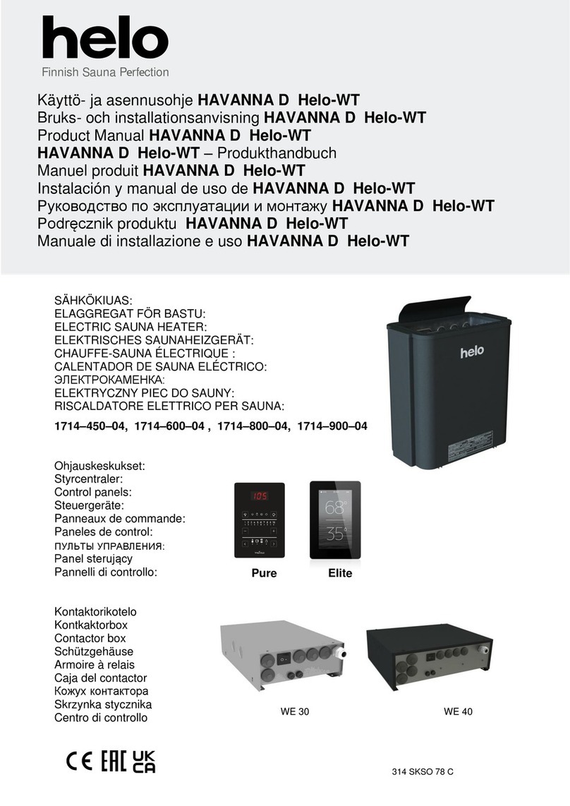
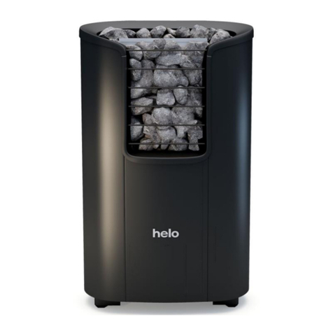
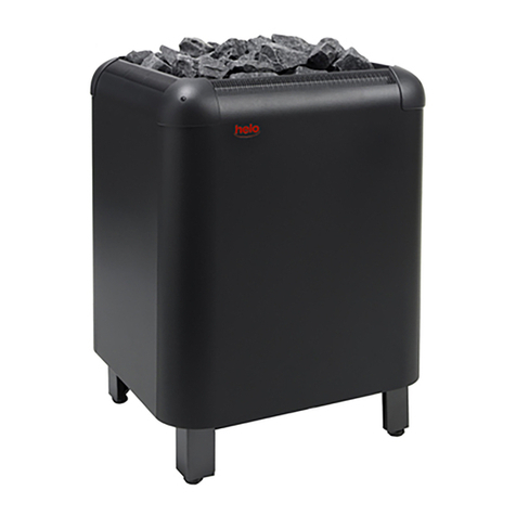
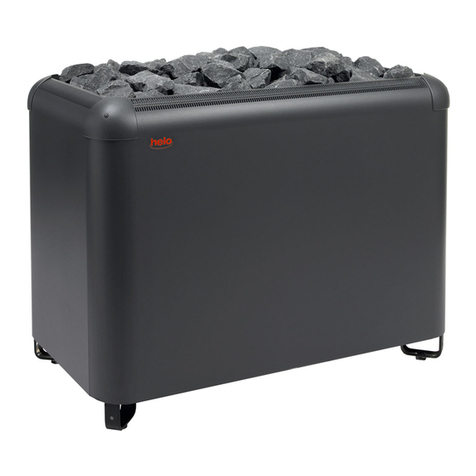
Helo RING WALL STJ User manual

ELECTRIC SAUNA HEATER
1716-450-171809
1716-600-171809
1716-800-171809
314 SKSR 11-3 A
Product Manual RING WALL STJ
REWARD YOURSELF

Contents
1. Quick instructions for use of the sauna heater 3
1.1 Check before taking a sauna bath 3
1.2 Operation of the sauna heater controls 3
2. Information for users 3
2.1 Sauna room 3
2.2 Recommended sauna room ventilation 4
2.3 Heating the sauna 4
2.4 Sauna heater stones 5
2.5 Sauna heater controls 6
2.5.1 Timer switch 6
2.5.2 Thermostat 6
2.6 Electric heating toggle 7
2.7 If the sauna heater will not heat up 7
3 Instructions for heater installation 7
3.1 Preparing for sauna heater installation 7
3.2 Installation 7
3.2.1 Sauna heaters installation 8
3.2.2 Changing the handedness of the heater 10
3.3 Main connection 10
3.4 Electric heating toggle 11
3.5 Location the connection box for connection cable in the sauna room 11
3.6 Wiring diagram 12
4. Spare parts for Ring Wall STJ-electric sauna heater 13
5. ROHS 14
Images and table
Image 1 Sauna room ventilation 4
Image 2 Safety clearances 9
Image 3 Location for the connection box 11
Image 4 Switch diagram for the sauna heater 12
Table 1 Safety clearances 9
Table 2 Connection cable and fuse 11
Table 3. Spare parts for Ring Wall STJ 13
Product Manual Ring Wall STJ 2

1. Quick instructions for use of the sauna heater
1.1 Check before taking a sauna bath
1. The sauna room is suitable for taking a sauna bath.
2. The door and the window are closed.
3. The sauna heater is topped with stones that comply with the manufacturer's recommendations, the heating elements
are covered with stones, and the stones are piled sparsely.
NOTE: Structural clay tiles are not allowed.
1.2 Operation of the sauna heater controls
The main switch of the sauna heater is located in the lower part of the sauna heater on the right beside the thermostat when
viewed from the front.
Set the heater's thermostat to the desired temperature. You can find the ideal temperature for taking a sauna bath by first
turning the thermostat to the maximum. Once the sauna room is warm enough, simply turn the thermostat control back-
wards, i.e. counter-clockwise, until the heating elements turn off (you can hear a clicking sound). You can fine-tune the tem-
perature by slightly turning the thermostat knob in either direction.
The sauna heater operates with a 12-hour timer.
The timer is operated by turning the timer knob clockwise from the 0 position.
In the 0 position, the power is off and the sauna heater is not on.
In the 0 3 hour zone, heating elements will turn on and the sauna heater is warm for the selected period of time.
In the 1 9 hours zone, you can preset the time after which the sauna heater will turn on. For example, by turning the knob at
6, the sauna heater will turn on after six hours and stay warm for three hours unless the timer is turned to the 0 position
earlier.
Rearrange the sauna stones at least once a year and replace any weathered stones. This enhances air circulation between
the stones, which extends the useful life of the thermal resistors.
If you encounter any problems, please contact the manufacturer's warranty service shop. A list of warranty service shops is
included in the delivery.
For additional information about enjoying a sauna bath, please visit our website at: www.helosauna.com
2. Information for users
Persons with reduced physical and mental capacity, sensory handicap, or little experience and knowledge about how the
device is operated (e.g. children), should only operate the device while supervised or according to instructions given by the
persons in charge of their safety.
Make sure that children aren't playing with the sauna heater.
2.1 Sauna room
The walls and ceiling of a sauna room should be thermally well insulated. All surfaces that store heat, such as tiled and
stone surfaces must be insulated. It is recommended to use wooden panel cladding inside the sauna room. If there are heat
storing elements in the sauna room, such as decorative stone, glass etc., note that these elements may extend the pre-
heating period even though the sauna room is otherwise well insulated (see page 7, section 3,1 Preparing ).
Product Manual Ring Wall STJ 3

2.2 Recommended sauna room ventilation
Image 1 Sauna room ventilation
1. Sauna room 3. Electric sauna heater 5. Exhaust flue or channel
2. Washroom 4. Exhaust valve 6. Door to the sauna room
7. A ventilation valve can be installed here to be kept closed while the sauna is heated and during bathing.
Inlet vent can be positioned in the A zone. Make sure the incoming fresh air will not interfere with (i.e. cool down) the sauna
heater's thermostat near the ceiling.
The B zone serves as the incoming air zone, if the sauna room isn't fitted with forced ventilation. In this case, the exhaust
valve is installed min 1m higher than the inlet valve.
DO NOT ISTALL INLET VALVE WITHIN ZONE C, IF THE SAUNA HEATER'S CONTROL THERMOSTAT IS LOCATED AT
THE SAME ZONE.
2.3 Heating the sauna
Before turning the sauna heater on, make sure the sauna room is suitable for taking a sauna bath. When heated for the first
time, the sauna heater may emit some odour. If you detect any odour while the sauna heater warms up, disconnect the
sauna heater briefly, and air the room. Then turn the sauna heater back on.
The sauna heater is turned on by twisting the timer knob, and the temperature is adjusted from the thermostat knob.
You should turn the sauna heater on roughly an hour before you plan to take a sauna bath, so that the stones have time to
heat up properly and the air warms up evenly in the sauna room.
Do not put any objects on the sauna heater. Do not dry clothes on the sauna heater or anywhere in its vicinity.
Product Manual Ring Wall STJ 4
55
4
4
2
1
1
1
A
7
A
min
500 mm
6
3
B
3
B
C
C
C
C A
1000 mm

2.4 Sauna heater stones
Quality stones meet the following requirements:
- Sauna stones should withstand heat and heat variation caused by vaporisation of the water thrown on the
stones.
- Stones should be rinsed before use in order to avoid odour and dust.
- Sauna stones should have an uneven surface to supply a larger surface for the water to evaporate from.
- Sauna stones should be large enough, measuring about 70 100 mm to allow good ventilation between the
stones. This extends the useful life of the heating elements.
- Sauna stones should be piled sparsely in order to enhance ventilation between the stones. Do not bend the
heating elements together or against the frame.
- Rearrange the stones regularly (at least once a year) and replace small and broken stones with new, larger
stones.
- Stones are piled so that they cover the heating elements. Do not, however, pile a large heap of stones on the
heating elements. For a sufficient amount of stones refer to Table 1 on page 9. Any small stones in the package
of stones must not be piled on the sauna heater.
- The warranty does not cover defects resulting from poor ventilation caused by small and tightly packed stones.
- Structural clay tiles are not allowed. They may cause damage to the sauna heater that will not be covered
by the warranty.
- Do not use soapstone as sauna rocks. Any damages resulting from this will not be covered by the stove
warranty.
- Do not use lava stone as sauna rocks. Any damages resulting from this will not be covered by the stove
warranty.
- DO NOT USE THE HEATER WITHOUT STONES.
Product Manual Ring Wall STJ 5

2.5 Sauna heater controls
2.5.1 Timer switch
The sauna heater is controlled by operating a 12-hour timer with three operating zones. The timer is set by twisting the knob
clockwise until the desired operating zone is reached. When operating, the timer gradually travels counter-clockwise towards
the zero position.
1. 0 position. The sauna heater is not on.
2. Operating zone 1 3 hours. Set on this zone, the sauna
heater heats up at full power while the sauna thermostat
controls the temperature.
3. Preset zone 1 9 hours. Set on this zone, the sauna heater
can be preset to turn on after a certain period of time. The
heating elements will not heat up when the timer is within
this zone.
Before turning the sauna heater on, make sure the sauna room
is suitable for taking a sauna bath.
The timer operates better if it is first turned further than the desired time
and then turned back to the desired time. If the switch has not travelled
back to 0 position after finishing bathing, turn it to 0 manually.
2.5.2 Thermostat
The thermostat knob is next to the timer knob. The further
right (clockwise) the timer is switched, the higher the
temperature will rise in the sauna room. The best way to find
the ideal temperature is to first turn the thermostat fully on
the right and let the temperature rise to the desired temperature.
Subsequently, turn the thermostat knob slowly counter-clockwise
until you hear a gentle clicking sound. If you want to readjust the
temperature, turn the thermostat gradually until the temperature
is ideal.
The thermostat will not operate correctly if the stones are piled too
densely or they are too sma
5
The thermostat has an integrated temperature limiter with a reset switch
next to the thermostat knob.
PA LA UT US RE TU R R ES ET TI NG
+
Product Manual Ring Wall STJ 6
01
2
3
1
2
3
4
5
6
7
8
9

2.6 Electric heating toggle
Electric heating toggle applies to homes with an electric heating system.
The sauna heater thermostat also controls the heating toggle. In other words, home heating turns on once the sauna ther-
mostat cuts power off the sauna heater.
2.7 If the sauna heater will not heat up
If the sauna heater will not heat up, please check that:
1. The power is on;
2. The timer is on the heating zone (operating zone);
3. The thermostat is switched to a temperature that is higher than the current temperature of the sauna room;
4. The front fuses of the sauna heater are intact;
5. The timer is not stuck. Make sure the knob doesn't chafe against the base; there should be min 1mm gap between the
knob and the base.
If the sauna heater has been exposed to freezing conditions, the temperature limiter may have gone off. The limiter is reset
by pressing the reset switch. Note that the limiter does not work until the temperature has risen to approx. -
heater still fails to work, please contact an authorised service for repair.
3 Instructions for heater installation
THE PERSON INSTALLING THE SAUNA HEATER SHOULD LEAVE THESE INSTRUCTIONS TO THE PREMISES FOR
THE FUTURE USER.
3.1 Preparing for sauna heater installation
Check the following before installing the sauna heater:
1. The ratio of the heater's input (kW) and the sauna room's volume (m3). Volume/input recommendations are
presented in Table 1 on page 9. The minimum and maximum volumes must not be exceeded.
2. The sauna room ceiling must be min 1900 mm high.
3. Uninsulated and masonry stone walls extend the preheating time. Each square metre of plastered ceiling or
wall surface adds 1.2 m3 to the sauna room's volume.
4. Check page 11 Table 2 section for a suitable fuse size (A) and the correct diameter of the power supply
stion.
5. Conform to the specified safety clearance around the sauna heater. Please refer to Image 2 Sauna heater
safety clearances. There should be enough room around the sauna heater for maintenance purposes, a
doorway etc.
3.2 Installation
Follow the safety clearance specifications on page 9 when installing the sauna heater. Thin panel is not a suitable mounting
base. The mounting base must be reinforced with timber behind the panel. The minimum clearances specified on page 9
table 1 must be followed also in case the sauna room wall materials are incombustible.
Walls or ceilings must not be clad with fibre-reinforced plaster board or other light-weight cladding, because they may cause
a fire hazard.
A single sauna heater is allowed per a sauna room.
Product Manual Ring Wall STJ 7

3.2.1 Sauna heaters installation
1. Prepare installation holes for the heater wall mount,
Note the necessary safety distance, see table 1 on page 9.
Screw in the upper bolts, leave the head ca. 2mm off the wall.
The lower bolts are installed and tightened at the end.
2. Turn the heater upside down. The installation holes (4x) for the wall
mounts are located in the bottom plate, see the arrows.
3. Install the heater wall mounts with the included
4,2 x 32mm screws (4x), as per the image.
Install the heater on the wall.
4. Install the lower wall mount bolts.
Tighten the upper bolts also.
Product Manual Ring Wall STJ 8

Image 2 Safety clearances
Effect
Sauna room Heaters minimum clearance
Minimum clear-
ance
to the panel
Amount
of stone
kW
Volume
m3
Min.
Height
mm
From the
front surface
A
mm
From the
front surface
D
mm
To
ceiling
F
mm
To the
floor
K
mm
B
mm
J
mm
circa. kg
4,5
6,0
8,0
4 6
5 9
8 13
1900
1900
1900
50
70
100
50
70
100
1200
1250
1250
120
120
120
170
190
220
230
230
230
37
37
37
Table 1 Safety clearances
Product Manual Ring Wall STJ 9
Minimum distances to the.
Mounting bracket (mm)
Screws 6 x 40 (2 pcs.)
Screws 6 x 16 (2 pcs.)
A A D
(mm) (mm)
445 350
210 B

3.2.2 Changing the handedness of the heater
By default, the thermostat and the timer switch are located
on the left hand side of the heater when viewed from the
front. They can be moved to the other side, if necessary.
The work may only be carried out by a qualified electrician.
1. Turn the heater upside down. Unfasten the bottom plate.
2. Pull the thermostat and timer knobs off.
Remove the two screws in the thermostat and timer body.
Remove the mains connector from the other side.
Remove the plastic caps of the electric housing from the
other side. Move the thermostat and the timer with their
body to the other side, and move the mains connector to
where the thermostat and timer were, secure with the two
screws. Attach the plastic caps to the empty holes.
Push the thermostat and timer knobs on.
NOTE: Leave at least a 1mm gap between the knob and
the outer shell of the heater.
3. Fasten the bottom plate, install the heater and check that it works.
3.3 Main connection
The sauna heater must be connected to the mains by a qualified electrician and in compliance with current regulations. Sau-
na heater is connected with a semi-permanent connection. Use H07RN-F (60245 IEC 66) cables or a corresponding type.
Other output cables (signal lamp, electric heating toggle) must also adhere to these recommendations. Do not use PVC
insulated cable as a connection cable for the sauna heater.
A multipolar (e.g. 7-pole) cable is allowed, if the voltage is the same. In the absence of a separate control current fuse, the
diameter of all cables must be the same, i.e. in accordance with the front fuse.
The connecting box on the sauna wall should be located within the minimum safety clearance specified for the sauna heater.
The maximum height for the connection box is 500mm from the floor.
If the connection box is located at 500mm distance from the heater, the maximum height is 1000mm from the floor. (Image
3 on page 11: Location for the connecting box).
Sauna heater insulation resistance: The sauna heater heating elements may absorb moisture from air, e.g. during storage.
This may cause bleeder currents. The moisture will be gone after a few heating sessions. Do not connect the heater power
supply through a ground fault interrupter.
However, always adhere to the effective electrical safety regulation when installing the sauna heater.
Product Manual Ring Wall STJ 10
1. Thermostat
2. Timer
3. Knobs
4. Overheating limiter reset
5. Mains connector
6. Plastic caps.
3
1
4
2 5
6

Effect
Heater connection
cable H07RN-F/
60245 IEC 66
mm2
400-415V 3N~
Fuse
A
Heater connection
cable H07RN-F/
60245 IEC 66
mm2
230V 3~
Fuse
A
Heater connection
cable H07RN-F/
60245 IEC 66
mm2
230-240V 1N~ / 2~
Fuse
A
4,5
6,0
8,0
5 x 1,5
5 x 1,5
5 x 2,5
3 x 10
3 x 10
3 x 16
4 x 2,5
4 x 2,5
4 x 6
3 x 16
3 x 16
3 x 25
3 x 4,0
3 x 6,0
3 x 6,0
1 x 20
1 x 35
1 x 35
Table 2 Connection cable and fuse
3.4 Electric heating toggle
Electric heating toggle applies to homes with an electric heating system.
Sauna heater has connections (marked N - 55) for controlling the electric heating toggle. Connectors N - 55 and the heating
elements are simultaneously live (230V). The sauna heater thermostat also controls the heating toggle. In other words,
home heating turns on once the sauna thermostat cuts power off the sauna heater.
Image 3 Location for the connection box
3.5 Location the connection box for connection cable in the sauna room
A = Specified minimum safety clearance
1. Recommended location for the connection box
2. Silumin box recommended in this area.
3. This area should be avoided. Always use a silumin box.
In other areas, use a heat- -
must be clear of obstacles. When installing the connection box to zones 2 or 3, refer to the instructions and reg-
ulations of the local energy supplier.
Product Manual Ring Wall STJ 11
A A
3.
2.
1.
A
A

3.6 Wiring diagram
1 2 3
1
2
3
kW SEPC 63 SEPC 64 SEPC 65
1500W 2000W 2670W
4,5
6,0
8,0
N N 55
B1 B2 B3
A1 A2 A3
354 SKSR 3 A
4 5 6
1. 2. 3.
1,2,3
1,2,3
12 3 6
4 5
230V 3~
L1 L2 L3
N
12 3 6
4 5
N L2
12 3 6
4 5
400V - 415V 3N~
L1 L2 L3
230V - 240V 1N~/ 2~
Vermogensingang / Entrada de
2. Merkkilamppu / Signallampa / Signal lamp / Kontrolleuchte /
Contact
/
/ Sterowanie ogrzewaniem elektrycznym
/
lampa sygnalizacyjna
230V
Teho, Effekt
Input, Potencia
Leistung, Moc
Puissance
Heating elements,
Elementy grzewcze,
,
1,2,3
Image 4 Switch diagram for the sauna heater
Product Manual Ring Wall STJ 12

4. Spare parts for Ring Wall STJ-electric sauna heater
Parts
Product
number Product title SKSR STJ 450 SKSR STJ 600 SKSR STJ 800
1 4071153 Basic grate 1 1 1
2 5509053 Clock OYKF 1 1 1 1
3 5408013 Thermostat
OLCH 1 1 1 1
4 7812550 Mains connector
NLWD 1-1 1 1 1
5 7712000 Cable clamp
NKWA 1 1 1 1
6 4309555 Knob
YWWA 11-2 2 2 2
7 4316222 Heating element SEPC 63
1500W/ 230V 3
7 4316221 Heating element SEPC 64
2000W/230V 3
7 4316220 Heating element SEPC 65
2670W/230V 3
Table 3. Spare parts for Ring Wall STJ
Product Manual Ring Wall STJ 13

5. ROHS
mukana, vaan se on toimitettava
-
Symboli tuotteessa,
n
Anv
handboken eller
gen refererar till detta.
ngscentralen
Instructions for environmental protection
This product must not be disposed with
normal household waste at the end of
its life cycle. Instead, it should be
delivered to a collecting place for the recycling
of electrical and electronic devices.
The symbol on the product, the
instruction manual or the
package refers to this.
The materials can be recycled according to the
markings on them. By reusing, utilising the
materials or by otherwise reusing
old equipment, you make an important
contribution for the protection of our environment.
Please note that the product is returned to the
recycling centre without any sauna rocks and
soapstone cover.
Please contact the municipal administration
with enquiries concerning the recycling place.
Hinweise zum Umweltschutz
Dieses Produkt darf am Ende seiner Lebens-
ltsabfall
Entsorgt werden, sondern muss an einem
Das Symbol auf dem produkt, der
Gebrauchsanleitung oder der
Verpackung weist darauf hin.
Die Werkstoffe sind ge
wiederverwertbar, Mit der Wiederverwendung,
der stofflichen Verwertung oder anderen Formen
wichtigen Beitrag zum Schutze unserer Umwelt.
Dieses Produkt soll ohne Steine und
Specksteinm
Bitte erfragen Sie bei der Gemeindeverwaltung
Product Manual Ring Wall STJ 14
This manual suits for next models
6
Table of contents
Other Helo Heater manuals
Helo
Helo Hanko STJ User manual

Helo
Helo 1106 - 901 User manual

Helo
Helo 1712-60-171817 User manual

Helo
Helo 0315-44-040518 User manual

Helo
Helo VIENNA D Series User manual

Helo
Helo ROXX PURE User manual

Helo
Helo 1105- 901-0104 User manual

Helo
Helo Vienna D User manual

Helo
Helo CUP 90STJ User manual

Helo
Helo FONDA DET User manual

Helo
Helo Ring1118-600-0405 User manual

Helo
Helo Viki Series User guide

Helo
Helo Havanna 450 D BWT User manual

Helo
Helo 1712-45-171817 Operator's manual
Helo
Helo Roxx Elite User manual
Helo
Helo Mini SA 1050216 User manual

Helo
Helo HAVANNA D User manual

Helo
Helo Rocher Pure User manual

Helo
Helo Himalaya DE User manual

Helo
Helo Laine STJ Series User manual